RoboCup@Home League 2013 BART LAB AssistBot (THAILAND)
Jackrit Suthakorn, Ph.D., Woratit Onprasert, Sakol Nakdhamabhorn, Rachot Phuengsuk, Yuttana Itsarachaiyot, Choladawan Moonjaita, Syed Saqib Hussain Shah, Peerapat Owatchaiyapong, Chawaphol Direkwatana, Watcharawit Saensupho, Maria Chatrasingh, Preedipat Sattayasoonthorn, Jitendra Yadav, Nantida Nillahoot, Karat Thanaboonkong, Pitchaya Rayothee, Nonthachai Soratriyanont, Shen Treratanakulchai, Sneha Patel
Center for Biomedical and Robotics Technology (BART LAB) Faculty of Engineering, Mahidol University 25/25 Phuttamonthon 4 Road, Salaya, Nakhon Pathom 73170 THAILAND
Abstract "BART LAB AssistBot Team", the robotics team from Thailand, has been continuously researching and developing service and assistive robot, and has been part of the Robot@Home Competition at a regional level since 2011. The team attended Thailand Robot@Home Championship 2011 and 2012 where it was awarded the "Best Creativity Award" and "Best Technique Award" respectively. The team first participated in an international competition in the @home robot league at RoboCup Japan Open 2012, Osaka. Using the international experience, the team developed a second iteration (AssistBot II); designed to reduce the limitations of the first generation. The team consists of nineteen members and one robot (AssistBot II). It is a highly mobile robot with an independent driving system. Furthermore, this robot is developed by applying localization, navigation and obstacles avoidance systems. There are two manipulators which are equipped at the left and right side of the robot body and are attached to mimic the appearance of the human body. The ultimate goal of the team is to produce robust services and assistive robots with the goal for human use. Keywords: BART LAB AssistBot, Robot@Home, and AssistBot II
Mechanical System
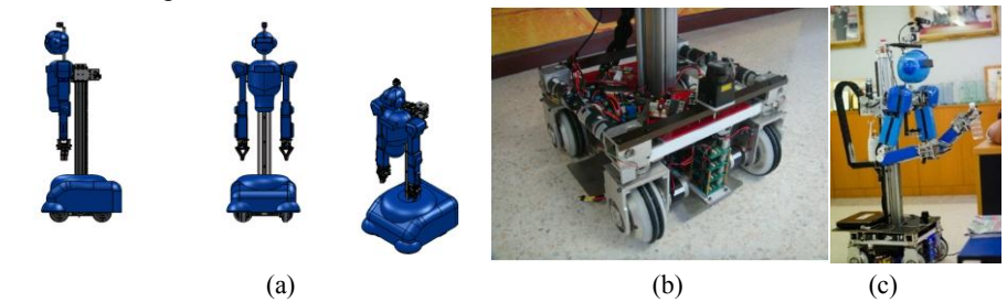
The robot is designed with a comprehensive mechanical system consisting of a driving system and manipulators. The independent driving system enables the robot to operate effectively in household environments.
Driving System
The robot is designed to operate in a house, so a small radius to turn is required. An independent driving system is used in the robot. There are a total of eight motors in the independent driving system. Four motors are designed for wheels, and the other four are used to change the direction of the wheels. The independent driving system is able to control a turning radius whereas a closed-loop control is applied to control direction and speed of the wheels. All of the motors are attached with optical encoder for closed-loop control feedback.
Another Mechanical System
There are two manipulators equipped on the left and right side of the robot body. Each manipulator consists of six degrees of freedom, and is attached to the robot to depict the human body.
- Two degrees of freedom: on the top which is designed to mimic the motion of human shoulder and at the joint to mimic the motion of human elbow
- One degree of freedom: is designed to mimic the motion of human wrist and to mimic the motion of human hand for grasping an object
Software Description
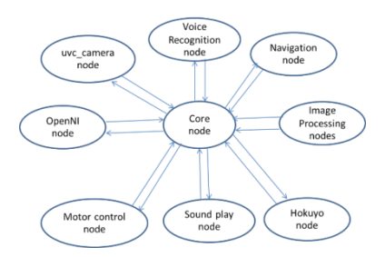
The software architecture of the robot is based on ROS (Robot Operating System), which combines several nodes to perform the specific tasks. The ROS nodes can be divided into two functions, which are the interfacing node and the processing node. The interfacing nodes are used to interface with common devices, such as, 2D range finder, RGB-D camera, RGB camera and sound input and output. The available ROS nodes are implemented to connect with these devices. For example, the 2D range finder is interfaced with laser_drivers package (hokyo_node) and the RGB-D camera is implemented with OpenNI package. For the processing nodes, we developed our ROS nodes to perform several tasks based on open source library, such as, OpenCV and OpenNI. For example, the image processing nodes perform object recognition, object location, and face recognition. All the ROS nodes can send and share data to each other. Therefore, the interfacing nodes can send the device data to the processing nodes to calculate the tasks, then the processing nodes send commands through motor control node to control the robot.
Software system architecture
The core node performs as a decision node or state control. In order to perform a certain task, the core node receives the user command from the voice recognition node, then makes a decision and updates a state of program to command interfacing nodes and processing nodes to process the task. The software detail in each task is discussed in the next section.
Follow me task
This task consists of a Hokuyo node, OpenNI node, Voice recognition node, sound play node and motor control node as interfacing nodes. We developed the follow me node by using the information from interfacing nodes.
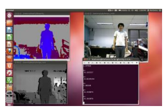
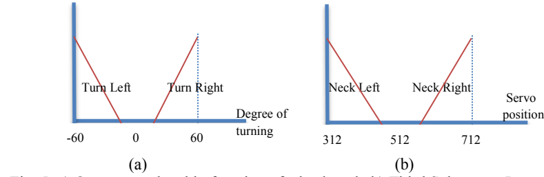
The follow me task of robot is based on fuzzy logic control and kinect OpenNI library for human detection. The main idea of this system is to follow the human and avoid the obstacles at the same time. The fuzzy logic controls have three subsystems separately. The first subsystem uses human position with respect to the robot head as an input to control the degree of robot's neck. With this subsystem, the robot will move its head in the horizontal plane to follow the human position. To achieve this operation in ROS system, we use OpenNI along with motion tracking middleware called NITE to track the human position as shown in the figure. The main advantage of using OpenNI and NITE for human tracking is the ability to identify multiple humans, define the ID for each tracked human and with the separately given tracked ID, one person can be followed when there are many people in the scene.
For example the control rule can be derived using the statement:
- IF Human_position is LEFT, THEN servo motor should turn LEFT or
- IF Human_position is FAR LEFT, THEN servo motor should turn FAR LEFT
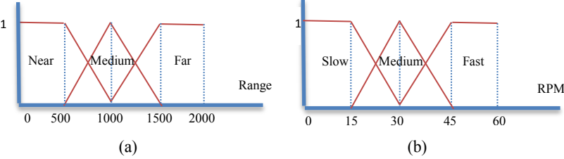
The second subsystem uses laser range data from laser range finder that is attached to the robot for the obstacles avoidance task. We use hokuyo laser range finder to collect the range data in fan shape in front of the robot. This data will then be divided into 10 ranges from left to right named position_1 to position_10. The input membership function for the second control system is shown below.
The control rule is based on experimental tuning of the robot and applied to two output membership functions of wheel speed and wheel angle. The output from the system will be applied separately to the four robot wheels which consist of driving speed and wheel angle.
The third subsystem uses the robot neck to follow the human by controlling the robot wheels. The servo position ranges from 312 – 712 in which 512 is the center rotation of neck. The input membership function of the third subsystem is shown below. The output of this system is similar to the second subsystem to control the speed and angle of the robot wheels separately. After calculation of all three subsystems are completed we combine the wheel speed and angle from the second subsystem and third subsystem by using weight of 0.7 for obstacle avoidance and 0.3 for human following. Therefore, the final output to control the robot is to follow the human by controlling the angle of wheel to make the robot heading parallel to the human heading.
Face recognition task
This task consists of OpenNI node, voice recognition node, and sound play node as interfacing nodes. We develop the face recognition node by using that information from interfacing nodes.
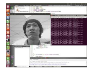
The face recognition node is developed based on OpenCV library. The human face is detected by Haar cascade for extracting human face from an image as shown in figure. For the recognition process, the training face images are extracted and stored into the databases. We use Principle Component Analysis algorithm (PCA) to recognize the human face from the training face databases.
Manipulation task
The manipulation task can be separated into two parts. The first part is the object detection and object recognition and the second part is the inverse kinematic to control the robot manipulators.
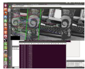
The object detection and object recognition program are developed based on OpenCV library. For the object detection and recognition, we use an image from Kinect RGB-D to find and detect an interesting object. The interesting object is extracted by using the depth information from Kinect. For the object recognition, the features of object are stored in the databases, such as, colors, shapes, and surface textures. These features are combined to recognize and locate the interesting object.
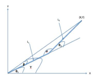
The inverse kinematics of the robot manipulator is calculated based on geometry solution. We model our inverse kinematic models as two link planar. The arm of the robot has two links with the length $L_1$ and $L_2$ for the arm and forearm of the robot respectively.
$$\theta_2 = \cos^{-1}(\frac{X^2 + Y^2 - L_1^2 - L_2^2}{2L_1 L_2})$$
Firstly, we find $\theta_2$ using the equation above. The $\Upsilon$ is calculated using equation below.
$$Y = Atan2(Y, X)$$
Next, we calculate $\varphi$ using the equation below.
$$\varphi = \pi - \theta_2$$
Then, we use sine law to find $\beta$.
$$\beta = Sin^{-1} \left( \frac{L_2 Sin(\varphi)}{L_1^2 + L_2^2 + 2L_1 L_2 Cos(\theta_2)} \right)$$
Finally, we calculate the $\theta_1$ by using equation below.
$$\theta_1 = \gamma - \beta$$
Navigation task
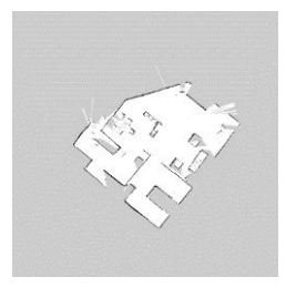
We generate a map by using gmapping algorithm. The gmapping is a SLAM open source for generating the 2D mapping. We implement the package on ROS and the requirement of gmapping is odometer data. We use incremental encoder for linear distance and use inertia measurement unit for robot heading. We also use gamepad to control a robot for collecting data, and then the laser range finder (HOKUYO URG-04LX) is used to generate a map. We use 180 degrees for scanning data and the rate of scanning is 100 ms/scan. The resolution of map is 0.05 m/pixel. In the map, the free space is shown as white pixel and the obstacles are shown in the black pixel. We use the map generated from gmapping for our robot navigation system. We implement a navigation system based on stack on ROS.
Scientific
The scientific approach of the robot encompasses several key areas of research and development in robotics and control systems.
Manipulator
The manipulators are designed to mimic the human motion. To grab an object, two cameras are used for object recognition and object localization. The inverse kinematic is used for approaching the object.
Independent drive
The independent drive system is controlled using microcontroller. One wheel consists of two degrees of freedom, one for driving the wheels and another one for changing the direction of wheels.
Independent drive control system
For a low-level control, the robot microcontroller is dsPIC30F4011 and is used to control the eight motors with the base platform drive, twelve drives for manipulator and one drive for body up-down. A motor controller can drive the motor current up to 9 amps continuously, and 30 amps peak. We use 2 power supplies to feed the motor controller (motor supply and logic supply) isolating between logic supply and motor supply for communication by using RS-485 bus communication to communicate with master. A motor controller is for slave mode and a computer is for master mode to control the slave via two twist-pair wire cables. Master connects to the media converter to convert the USB signal to RS-485 for suitably with motor controller and connecting with 20 motor controllers. It also can connect with 1). incremental encoder, 2). hall effecting sensor, directly for controlling the angle of 4 wheels using incremental encoder, and 3). hall effecting sensor to measure and control the angle of each wheel and send an angle to master to monitor the wheels of robot. Furthermore, an incremental encoder is applied to main motor for a robot speed measurement in both forward and backward movement.
Research Interests and Application
@Home robot is a research project for medical application. The project can be operated in logistics and service in hospitals. For logistics, the robot can be used to carry drugs and medical supplies to reduce a workload for routine work. For the service approach, the robot can communicate with and navigate a patient to the right department in a hospital. In addition, robot can keep basic information of patient such as blood pressure measurement, temperature checking, and database of patient. We are also involved with the rescue robot research. In order to develop the autonomous robot for rescue research, the software of the autonomous robot is based on the ROS system. Therefore, Several ROS packages of the robot at home can be used or shared with the rescue robot research. Moreover, the hardware controlling system between robot at home and rescue robot uses the same protocol therefore the controlling software can be used in both of the research areas.
Basic work of a robot in a hospital
Basic work of a robot in a hospital can be applied to use in the @Home robot:
- Robot can communicate to human by using speech
- Robot can navigate itself in hospital area by mapping-based generation
- Obstacle avoidance is important in the hospital area and localize itself
The advantages of using robot in logistics
The advantages of using robot in logistics are:
- Robot can carry more load than a human
- Robot does not need to take a rest. It can run continuously
- Robot can work on weekend and does not avoid its duty
The advantages of a robot in hospital service
The advantages of a robot in hospital service are:
- Robot do not need to take a break and can service a patient incessantly
- Robot can operate the works repetitively
Applications
The robot has the following applications:
- The robot uses in the hospital service
- The robot uses in the hospital logistics
References
- Documentation ROS Wiki, http://www.ros.org/wiki/
- OpenCV Wiki, http://opencv.willowgarage.com/wiki
- John J. Craig. "Introduction to Robotics Mechanics and Control," Addison Wesley Publishing Company, Inc. 2nd Ed. ISBN 0-201-09528-9.
- Timothy J. Ross "Fuzzy Logic with Engineering Application," John Wiley & Sons Ltd, ISBN 0-470-86075-8.