Team Description Paper: Team Dong Yang in 2013 RoboCup @Home League
Pruittikorn Smithmaitrie, Chalita Hiransoog, Warit Wichakool, Supparak Sangsaikeaw, Pongsakorn Chanchaichujit, Anwar Rajawana, Somkait Naktanom, Peerayuth Saekow
Department of Mechanical Engineering, Faculty of Engineering, Prince of Songkla University, Hat Yai, Songkhla, 90112 Thailand
Abstract A home service robot has been developed by Team Dong Yang for RoboCup @Home league competition since 2011. Recently, The Robot has been awarded a co-winner in the 2012 Thailand Robot Championship. The abilities of the robot are improved aiming for the real life implementation and usage in the house and human-living places. The robot structure, components, controller and progamming are presented in this work.
1 Introduction
A group of students and faculties, named Team Dong Yang, in the field of mechatronic engineering, the department of mechanical engineering, faculty of engineering, Prince of Songkla University has built and developed a domestic service robot, originally for the competition since 2011. The achievement has continuously gained as follows, the second place and the best robot-human interface in the 2011 Thailand Robot Championship, the 11th Rank in the 2012 world RoboCub at Mexico, and recently was a co-winner in the 2012 Thailand Robot Championship in Robot @Home league. The robot also has been developed as well as knowledge based on implementation of existing technologies. In this paper, the structural and mechanical designs of the robot, sensors, actuators, components, controllers and programming are described as follows.
2 Structural and Mechanical Designs
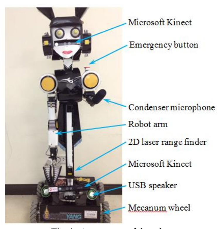
Main structure of the robot as shown in Figure 1 consists of head, body, arm and base. The structure is made of aluminum profile beams and plates. The outlook design is based on the survey from a group of people preferences [1]. The body of the robot is a square-cross-section pole where the robot arm, display, Kinect sensors, and microphone are attached on. The wheel base has 4 Mecanum wheels with a 2D laser range finder in the front, inside containing batteries and controllers.
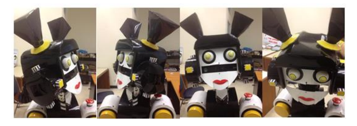
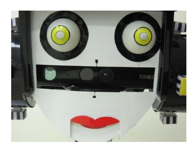
The head of the robot has a Kinect camera working as robot's eyes, and two Dynamixel servo motors that control the robot head for moving left-right and updown as a neck as illustrated in Figure 2.
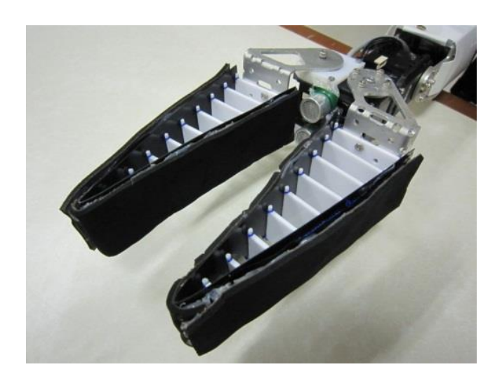
The robot's arm is made of folded aluminum plates. The arm position is controlled by 4 Dynamixel servo motors which produce 4 degrees of freedom [2]: two motors control the shoulder, one motor controls the elbow, and one motor controls the wrist as shown in Figure 3. A fin-ray effect gripper is controlled by a servo motor.
![Fig. 3. The 4-DOF robot arm with a fin-ray effect gripper [2]](/tdps/athome_open__2013__Dong_Yang/_page_2_Picture_1.jpeg)
The robot's gripper makes use of the fin-ray effect principle, developed by Festo [3]. The advantages of this technique are that the gripper is able to wrap around round shape objects, increasing contact grasping area and reducing contact force occurred on the object surface. An ultrasonic sensor is attached inside the robot hand for measuring a distance between the grasped object and the gripper.
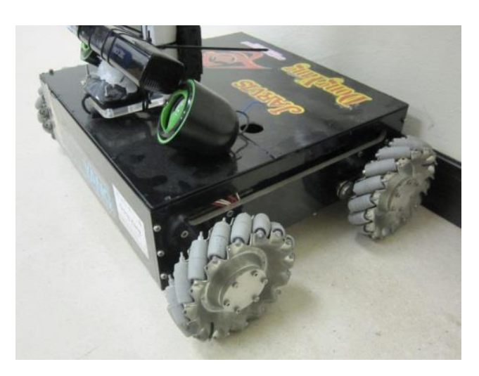
The robot's wheel base is made of aluminum plates, containing four motors, microcontroller and batteries. Each of four motors controls each of Mecanum wheels as depicted in Figure 4. The set of Mecanum wheels enables the robot to move and rotate in various directions without steering mechanism. It also can drive through narrow spaces.
3.1 Input Sensors
The gripper sensor: An ultrasonic sensor is placed between two fingers of the gripper in order to detect and measure the grasped object distance as shown in Figure 5.
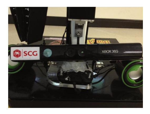
The image sensor: The Microsoft Kinect sensor [4] and C# programming is implemented for face recognition, object recognition and Human's skeleton tracking. The Kinect sensor provides useful data such as real-time color images and depth of those pixels with respect to the camera. By using two Kinect sensors, one is placed in the robot head (Figure 6) working as robot's eyes, and another one is placed on the robot's base (Figure 7) to track a human's skeleton in the following human task.
Voice sensor: A directional condenser microphone is placed beside the robot's body. The microphone has a good noise cancellation that makes the speech recognition more effective, so that the robot can be commanded by speech easily in noisy environments.
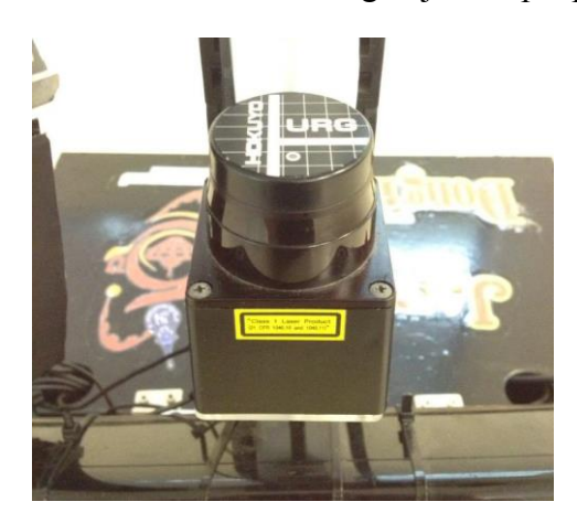
Navigation sensor: A 2D laser range finder sensor (HOKUYO) is placed in front of on the robot's base as shown in Figure 8. The HOKUYO sensor can measure distance of the object providing data for robot localization and mapping system. Moreover, it can be used to avoid obstacles or to track moving object or people.
3.2 Outputs and Display
The robot voice output device is an ordinary portable USB speaker connected with the robot's computer. This enables the robot to speak to human. In addition to the computer screen, the image display can be done via a LCD screen or tablet.
4 Control System and Programming
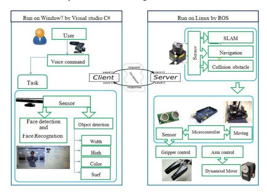
Recently this year, the combination of two operating systems (OS) in one robot is developed. The first one is Windows OS with C# programming. The speech recognition, speech synthesis, object recognition and face recognition are working on Windows OS environment. The second one is the Ubuntu OS which running ROS (Robot Operating System). The motion control, localization and mapping, and robot arm control system are programmed in the ROS. There are two laptops for processing each operating system independently and communicate to each other by using cross over LAN cable for transmission and receiving data. The reason of the use of two operating systems is that both OSs have their own advantages. Microsoft Windows OS has well developed voice recognition, voice synthesis, and Kinect sensor interface. The ROS on Ubuntu has open-source program libraries available for mapping and navigation, allowing fast learning and development for the robot programmer. Thus, the control and processing steps between the two computers are that the Windows computer takes and processes both voice and image inputs. Then, the processed command will be sent to the ROS computer to do the navigation, or control the robot arm, or microcontroller for driving the wheels.
The main software is programmed with Visual Studio C# with EMGU library. These are Windows OS based software. The diagram of software communication between two different OS computers is illustrated in Figure 9.
The second software is programmed based on ROS, because of availability of the open-source mapping and localization system. It is easy for implementation on the robot. In the mapping process when the robot initially travels around the house, it will create a map of the house by using data from the laser range finder and make a 2Dgridmap as shown in Figure 10 (Right). Moreover, the data from the 2D laser range finder is also used for localization of the robot to determine its position on the map.
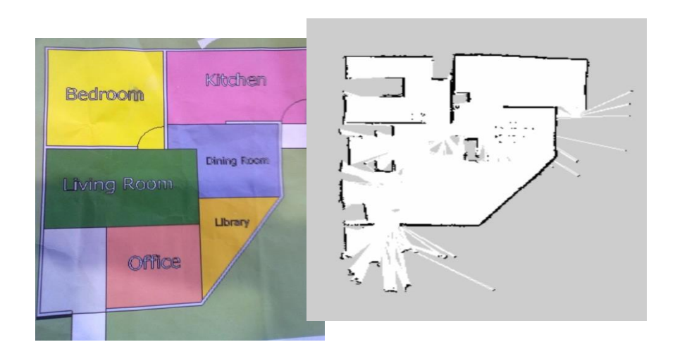
When the robot knows its own location on the map, the control system will calculate the path and direction where it should go, so called navigation system. Then, the computer will send the signal to the microcontroller to control the robot wheels. Finally, an Arduino microcontroller [5] is used for controlling the driving system and processing the sensing input data.
5 Summary
The home service robot is a developing project for competing in 2013 RoboCup @Home league in Netherlands. The system including structure, actuators, sensors, controllers, and operating system have been reported. It has shown that existing technologies can be integrated and create an intelligent system to serve people in their living space as a service robot. From the last year, Team Dong Yang has improved the robot performance and created more friendly appearance robot. As far as the RoboCup competition goes, it shows that possibility of a real home service robot is the coming future.
Acknowledgements
The authors would like to thank staffs and students at the Mechanical Engineering Department, Engineering Faculty, Prince of Songkla University, Thai Robotics Society (TRS), Siam Cement Group (SCG), PTT Global Chemical, PSU Engineering Alumni and many others for their supports, without them the team could not come this far.
List of Components
Microsoft Kinect sensors, Mecanum wheels, Dynamixel servo motors, DC motors, Ultrasonic sensors, Arduino microcontrollers, Hokuyo 2D Laser range finder sensor, USB portable speaker, Directional condenser microphone, Tablet, Microsoft Windows, Visual Studio C#, EMGU, OpenCV, ROS, Ubuntu.
References
- Chanchaichujit, P., KanjanaKaew, E., Smithmaitrie, P.: Appearance Design of a Robot for In-House Applications. In: 2012 TRS Conference on Robotics and Industrial Technology (CRIT 2012), Nov 28-29, 2012, Nakorn Pathom, Thailand, pp. 121-125. (2012) [in Thai]
- Bomlai, P., Rachawana, A., Smithmaitrie, P.: Design and Inverse Kinematic of a Robot Arm and Gripper for Robots at Home Applications. In: 2012 TRS Conference on Robotics and Industrial Technology (CRIT 2012), Nov 28-29, 2012, Nakorn Pathom, Thailand, pp. 22-26. (2012) [in Thai]
- Festo, Festo Fin Ray Effect, Future Concept for Fin Ray Effect, http://www.festo.com/cms/en\_corp/10987.htm/ [Accessed February 8, 2013]
- Microsoft Cooperation, Microsoft Kinect for Windows, Develop for the Kinect, Kinect for Windows, http://www.microsoft.com/en-us/kinectforwindows/ [Accessed February 8, 2013].
- Arduino, Arduino HomePage, http://arduino.cc/en/ [Accessed February 8, 2013].