SKUBA 2013 Team Description
Kanjanapan Sukvichai, Teeratath Ariyachartphadungkit, Bhirawich Pholpoke Krit Chaiso, Jirarote Jirasirikul, Kittipon Kanda, Sutinai Tanalerkchai
50 Ngarmwongwan Rd, Ladyao Jatujak, Bangkok, 10900, Thailand
Abstract This paper is used to describe the SKUBA @home League robot team from Thailand. SKUBA@home is designed under the World Robocup 2012 rules. Based on the last participation, this year, we're focusing on the new base platform which designed by using mecanum wheels and concentrating on ways to improve the performance of object recognition. The overview describes both the robot hardware and the overall software architecture of our team.
Introduction
SKUBA @home was established in 2011. In 2012, SKUBA @home made the first participation in Robocup Japan Open 2012 and made the way through finalist. Furthermore, SKUBA @home joined the World Robocup 2012 in Mexico and managed to pass to the 2nd stage as we anticipated. From last year issued, we decide to improve our robot performance by using mecanum robot platform in order to solve the "Walking in Elevator" issue. Thus, this year we hope to complete the "Follow Me" task. Furthermore, Team has developed a new object recognition technique.
The next section will explain about our robot that is designed for further research in the future. In the 3rd section is about software architecture and also includes object recognition algorithm. Section 4 will explained is about lower level design and model of the robot including robot motion and robot odometry estimation. Finally in the last section, we will present the conclusion.
New Robot
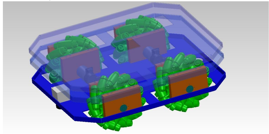
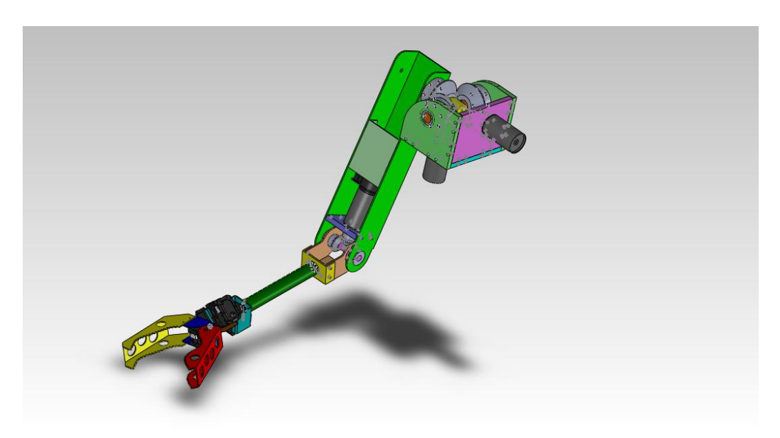
The new SKUBA@Home platform is designed as a three layer platform. The first layer is the driving mechanism layer. Second layer is a robot body which can be moved in vertical and the last layer is robot head and arm. Robot driving mechanism base consists of four 8" mecanum wheels. Each mecanum wheel is driven by Maxon EC 45 flat (brushless motor, 70 watt) BLDC motor combined with planetary gearhead of 1:36 gear ratio. The Hokuyo laser length finder is attached to the lower layer in order to obtain the environment information which will be used in SLAM algorithm. This mecanum wheel has more mobility than the regular fixed wheel since it provides side movement. Now the robot can easily avoid the obstacles and has more flexibility to maneuver to the massy environment. The robot mecanum base is shown in figure 1 below.
Software Architecture
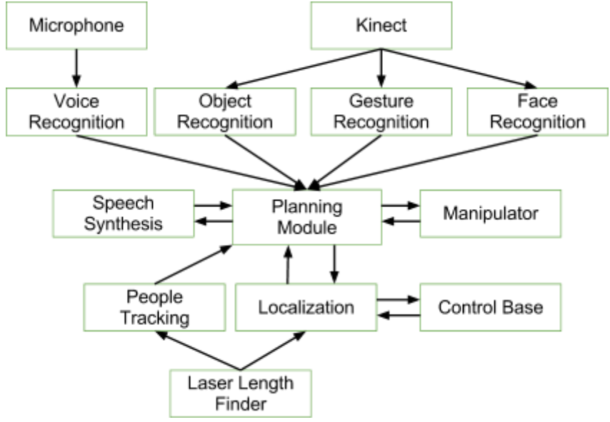
All high level software is running on ROS (Robot OS). The high level architecture can be divided into 3 separated modules as figure 3. The input information comes from 3 sources which are data from laser length finder, sound from microphone and color and depth picture captured by Kinect.
Speech Recognition
The pocketsphinx base on CMUSphinx speech recognizer is selected as the robot speech recognition tool. It uses gstreamer to automatically split the incoming audio into utterances to be recognized. Currently, the recognizer requires a language model and dictionary file. These can be automatically built from a corpus of sentences using the Online Sphinx Knowledge Base Tool.
Object Recognition
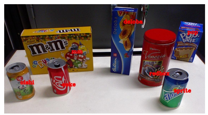
In order to extract interested objects from the background plane the following Euclidean cluster extraction algorithm [1] is used. By doing this, the cluster of objects with HSV and depth data is obtained from Kinect device. Histogram of objects is processed on order to recognize the ready-learned colors. During that process, SURF algorithm is also used to recognize pattern of the object. Finally, the combination of two results of both processes can be done by using threshold to decision where object belong as shown in figure 4.
Gesture Recognition
Nite algorithm is the algorithm built in OpenNI framework can retrieve motion gesture such as wave, circle, swipe, push and steady. This algorithm return with hand position of all gesture detects. Moreover, it can be detect more than one gesture at a time. Therefore, we select Nite algorithm as our gesture recognition algorithm.
Face Recognition
The Haar like Features Cascade is used to detect faces. Moreover, we modified the input data by using of depth data from Kinect sensor in order to cut the background plane. In face recognition, simple eigenface technique is used.
Speech Synthesis
The e-speak is selected as the robot speech synthesis software which uses a "formant synthesis" method. This allows many languages to be provided in a small size. The speech is clear, and can be used at high speeds, but it is not as natural or smooth as larger synthesizers which are based on human speech recordings.
Planning Module
This is the main control states module which used to process data from all input module include Speech Recognition, Object Recognition, Gesture Recognition, Face Recognition, and People Tracking and Localization. The module makes decision which environment that robot percept and which state will do next. All state is in mealy machine style.
Manipulator
This module is intermediate between Planning module and USB-to-RS485 which exchange data from Planning module and the joint motors. This module constructs to be compatible with motor hardware and it returns standard message with ROS format.
People Tracking
People tracking can be done by using a laser scanner as a robot sensor. By using the Maximum likelihood approach algorithm associate data in the validation region and using Kalman filter, that has a constant velocity model system, as a filter. We can determine the position of the person.
After grabbing a person current position, the position will be redirect to Path planner module to locate the path from robot to the person. Meanwhile to solve the problem of robot moving to close to the obstacles, we have to modify the path with elastic band approach to make the path as center as possible.
Localization
Hokuyo laser length finder which acquires environment data is attached to the robot in order to implement localization algorithm. Additionally, the robot odometry information is also considered as one input information to localization algorithm.
AMCL (Adaptive Monte Carlo Localization) system is used for robot localization. AMCL is a probabilistic localization system for a robot moving in 2D. It implements the adaptive (or KLD-sampling) Monte Carlo localization approach (as described by Dieter Fox), which uses a particle filter to track the pose of a robot against a known map.
This known map is acquired with OpenSLAM Gmapping Package which is a highly efficient Rao-Blackwellized particle filter to learn grid maps from laser range data.
ROS navigation stack is used for robot navigation. A 2D navigation stack that takes in information from odometry, sensor streams, and a goal pose commands safe velocity to a mobile base.
Low level design and control
The low level layer is composed of motor control module and odometry estimation module. It is implemented in embedded system on the robot chassis.
Motor control module
Motor control module is based on Spartan 3 FPGA from Xilinx. The FPGA contains a soft 32-bit microprocessor core and peripherals. This embedded processor executes the low level motor control loop, communication and debugging. The motor controller, increment quadrature decoder, PWM generation and onboard serial interfaces are implemented using FPGA. The PI controller is employed to achieve each wheel velocity.
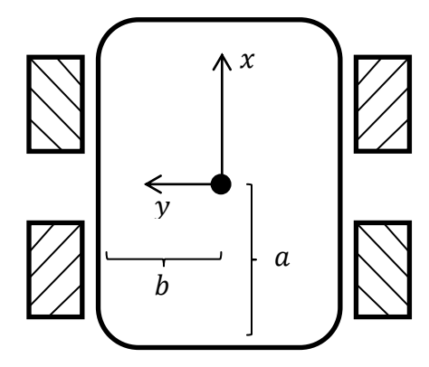
Odometry estimation module
This module helps to minimize the mean square error of the non-perfect sensor measurement originated from wheel slippage, dynamic surrounded environment and IMU drift over time. Using the laser scanner to estimate the change of position by laser scan matching technique can solve the wheel slip problem while facing with high sensitivity to dynamic environment. On the other hand, estimating the position by double integration of accelerometer causes the quadratic error due to bias noise as seen in IMU model equation (2)
$$z_{measurement} = z_{ture} + bias + w_{gaussian}$$
(2)
IMU Bias Noise Correction
Because of bias noise illustrated in (2) is a very low frequency noise. Therefore, it can be determined offline every time when the robot is stopped more than predefined time. The exponential moving average method is used to smooth bias value.
$$bias_k = bias_{k-1} + K(z_k - bias_{k-1}) \tag{3}$$
Where $K$ is the forgetting rate constant of the past bias value and $z_k$ is the measurement from IMU. The raw information from IMU has to be corrected by bias value in (3) before the use in next steps.
Kalman's Equations
Robot Operating System (ROS) is selected as the robot operation platform. It has built-in source laser scan matcher algorithm module which uses Point-to-line distance Iterative Closed Point (ICP) [2][3] method. These information and wheel encoders are the measurement information for the Kalman filter while acceleration from accelerometer is the control input in order to predict the present state variables at each sampling time because it is independent on ground surface and surrounded environment.The prediction equation for the Kalman filter is constructed as seen in (4)
$$\begin{bmatrix} \hat{v}x^- \ \hat{v}y^- \end{bmatrix}k = \begin{bmatrix} 1 & 0 \ 0 & 1 \end{bmatrix} \begin{bmatrix} \hat{v}x \ \hat{v}y \end{bmatrix}{k-1} + \begin{bmatrix} a{acc,x} - bias{acc,x} \ a{acc,y} - bias{acc,y} \end{bmatrix}_k \Delta T \tag{4}$$
Where $a_{acc}$ is the measurement from accelerometer and $bias_{acc}$ is determined in (3). The process noise covariance for the prediction step is $Q$ which can be found in sensor specification or by experiment.
For the measurement step, linear velocities of the robot from wheel encoders can be transformed by using equation (1). Numerical differentiation of the position which is published from ROS laser scan matcher nodes is used as another measurement variable for a Kalman filter. The relationship between a state variable vector and a measurement vector can be written as
$$z_k = \begin{bmatrix} v_{lsm,x} & v_{lsm,y} & v_{en,x} & v_{en,y} \end{bmatrix}^T = \begin{bmatrix} 1 & 0 & 1 & 0 \ 0 & 1 & 0 & 1 \end{bmatrix}^T \begin{bmatrix} v_x \ v_y \end{bmatrix}_k$$
(5)
Where the subscript $lsm$ is information from a laser scan matching method and $en$ is information from wheel encoders. The measurement covariance matrix is $R = diag([R_{lsm}, R_{en}])$ where $R_{en}$ comes from an experiment and $R_{lsm}$ is based on the analysis of the ICP's error function which can be found closed form solution in [3]. That increases when a robot is in such a dynamic environment causes the Kalman filter weights its gain to wheel encoders more. As a result, the overall estimation accuracy is improved.
Experiment Results
The experiments are setup in order to confirm the robot performance. In this experiment the prototype of robot mecanum base is used. This prototype uses the same concept of the real robot but in smaller scale. The experiments are setup in order to compare the purposed algorithm technique with other techniques. The robot trajectory is assigned and tested on different algorithms. Robot odometry is estimated by wheel encoders, Laser Scan Matching (LSM), fusion of IMU and wheel encoders and fusion of IMU, LSM and wheel encoders.
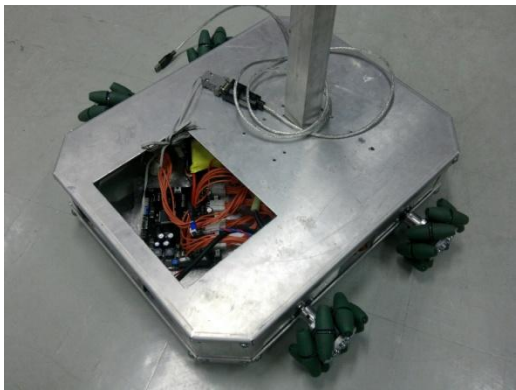
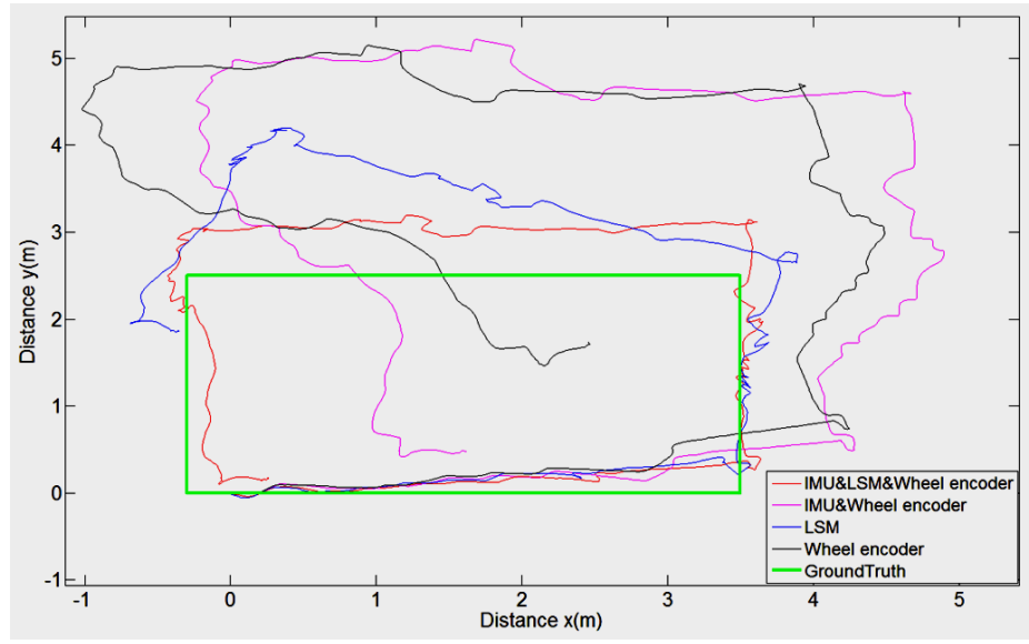
Table 1. The comparison of MSE in every method.
| Method/MSE | x (m) | y (m) |
|---|---|---|
| IMU&LSM&Wheel encoder | 0.0108 | 0.1630 |
| IMU&Wheel encoder | 0.7865 | 2.1470 |
| LSM | 0.0764 | 1.1837 |
| Wheel encoder | 1.0001 | 2.5738 |
Conclusion
In this year, we mainly focus on developing more stable robot and also it's AI software. We'll improve performance of manipulator as future work. We have experiences from Robocup @Home competition 2012 and we learn from our mistakes. Our robot and AI are improved in order to join RoboCup 2013 event in Netherlands. We hope that our robot team will perform better in RoboCup than the previous year, and we are looking forward to sharing experiences with other great teams around the world.
References
- Serkan Tuerker, "Euclidean Cluster Extraction", http://pointclouds.org/documentation/tutorials/cluster_extraction.php#cluster-extraction .
- A. Censi, "An ICP variant using a point-to-line metric", In Proceedings of the 2008 IEEE International Conference on Robotics and Automation, 2008.
- A. Censi, "An accurate closed-form estimate of ICP's covariance", In Proceedings of the 2007 IEEE International Conference on Robotics and Automation, 2007.