Team TRCC RoboCup 2013 RoboCup@Home League Team Description Paper
Thavida Maneewarn, Tipwimol Sooktip, Kaned Thungod, Navapan Suparat, Jeerawan Aurmyou
Thonburi Robot Contest Club King Mongkut's University of Technology Thonburi (KMUTT) 126 Pracha Uthit Rd., Bang Mod, Thung Khru, Bangkok 10140, Thailand
http://trccrobotathome.blogspot.com/
Abstract This paper introduce the TRCC team and our robot for the RoboCup@Home competition in 2013. TRCC is an acronym for the Thonburi Robot Contest Club at King Mongkut's University of Technology Thonburi in Thailand. TRCC team won the Thailand Robot@Home Championship in December 2012. Therefore, this is first time of the TRCC team to participate in the world RoboCup@Home competition. Our robot 'TRCC-422R' performs general abilities of a home service robot as required by the rules of the RoboCup@Home league such as indoor navigation, face and human recognition, object manipulation and interaction with humans. This paper provides an overview of the hardware components, software specifications, perception algorithm and behavior control of our robot.
1. Introduction
Since 2011, Thonburi Robot Contest Club or TRCC has developed the home service robot for participating in the Thailand Robot@Home Championship. The TRCC team comprises of undergraduate and graduate students from Thonburi Robot Contest Club (TRCC) of King Mongkut's University of Technology Thonburi. The team won Thailand Robot@Home Championship in 2012. Consequently, our team has a support from the Thai Robot Society (TRS) to enter the world Robocup @home 2013 in Netherlands.
This paper provides the detailed description of the TRCC-422R robot for the competition in the RoboCup@Home league 2013. The robot is developed based on an open source library with C# programming language.
2. Robot Design
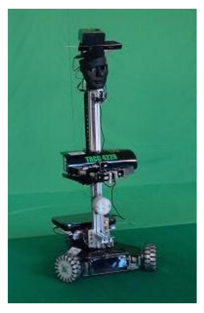
The robot that is designed and built for Thailand @Home competition in 2012 is called 'TRCC-422R'. The base of this robot has three omnidirectional wheels as shown in Figure 1. With this design, the robot can move toward any direction without the need of steering. The speed of each wheel is controlled to the desired velocity which is calculated from the inverse kinematics equation. Sensors and the robot arm are attached at the column at the middle of the robot. The robot arm can slide up and down in order to manipulate objects at different heights.
The robot structure made of aluminum because this material has lightweight and high strength. The lower part of the robot carries a notebook computer, electronics boards and batteries. The robot can move at a maximum speed of 0.6 m./sec. with weight 25 kg. and height 1.5 m. The robot arm has 6 degrees of freedom and can lift a 1.5 kg payload.
3. Sensors and Perception
Robot Arm Sensor
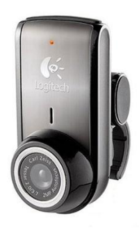
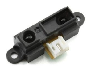
There are 2 type of sensors attached at the robot arm including a Logitech webcam Pro camera and an infrared sensor as shown in Figure 2 and 3, respectively. These two sensors are used together for object identification in the manipulation task. The camera identifies an object location from the perceived image while the infrared sensor which attached at the end-effector allows the robot to locate an object more precisely.
Localization and Navigation sensor
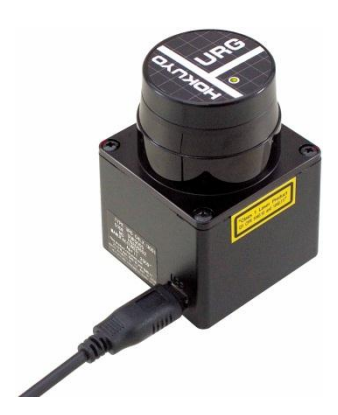
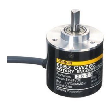
For localization and navigation purpose, the Hokuyo URG04LX Laser and the incremental encoder are used as shown in Figure 4 and 5, respectively. This laser scanner has 5.6 m. maximum range and 240 degrees field-of-views. The incremental encoder measures angular velocity of each wheel. The measurement from an incremental encoder on all three wheels are gathered and used as odometry information for a robot.
Human Recognition Sensor
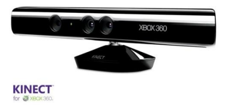
In Figure 6, the KINECT camera is used for skeleton tracking and identifying human.
4. Software
The software for this robot is implemented using C# programing language with the EMGU library for human recognition, face recognition, speech recognition, selflocalization and mapping.
1. Human Recognition
Microsoft Kinect SDK is used to implement Kinect Skeletal Tracking [1]. The full body of human has to be visible for the system to be able to recognize as human at the initial condition. Thereafter, the microcontrollers control the robot wheels to follow the human.
2. Auditory Perception
Speech is recognized using Microsoft Speech SDK. Before speech recognized process, the vocabulary or sentence commands are adding. The complex commands which a long sentence can recognize and then the robot response appropriate behavior.
3. Perception of Objects
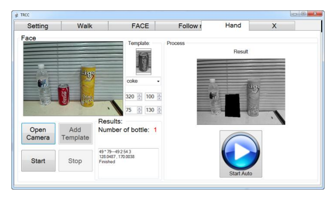
The Objects are recognized by using SURF (Speeded Up Robust Features) [2, 3] for Object Recognition from EMGU library. The images of object are recorded from different viewpoints during training to created data set. The detected objects are extracted SURF features and mapped into the image data set. Then computer sends the control signals to the microcontroller. After that the robot use arm to grasp the target object according to the locations of the object in the frame. The object recognition user interface is shown in Figure 7.
4. Face recognition
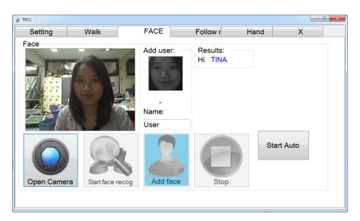
The faces are recognized by using Haar-like features [4, 5] for Object Recognition from the EMGU library. The images of faces are recorded from the users during training to created data set. The detected face are identify according to the user faces data set. The face recognition user interface is shown in Finger 8.
5. Self-Localization and Mapping
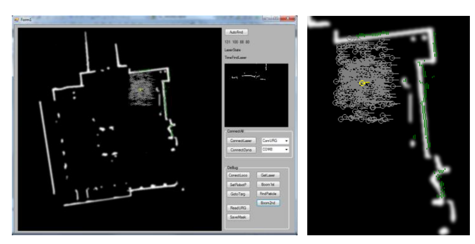
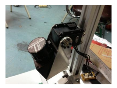
The laser scan sensor and an incremental encoder are used to for pose estimation and locating the position of the robot with Particle Filter Algorithm [6]. The Particle Filter Algorithm find local position of the robot in a 2 dimensional map as shown in Figure 9. In Figure 10, the laser scan and motor rotation are used for obstacle avoidance by a 3 dimensions map that is created from the laser data.
5. Control Systems
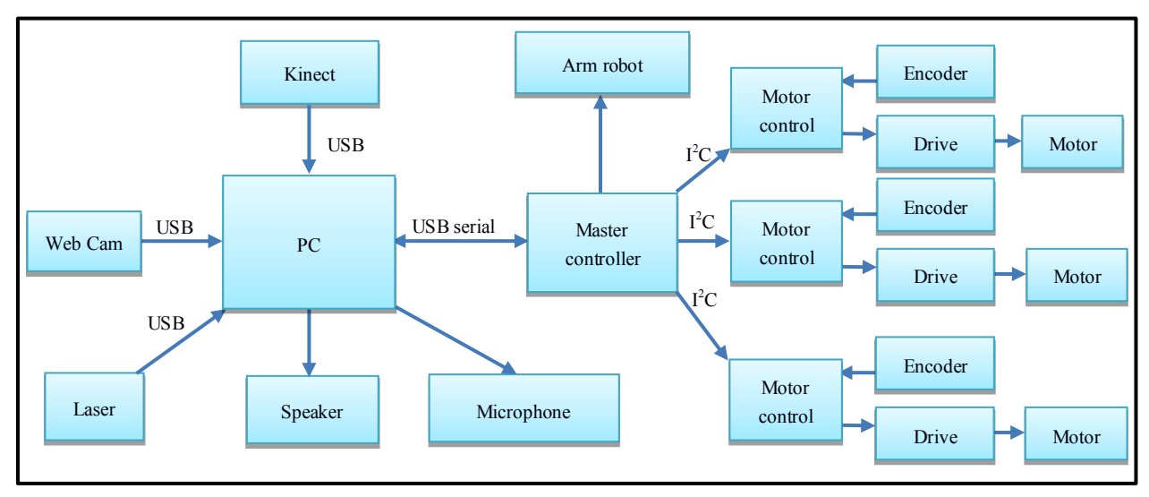
The low-level robot behavior is controlled by the program on an AVR MEGA1280 Microcontroller. The Microcontroller controls the movement of the robot and the robot arm, and communicates with the computer to perform the tasks. The diagram of robot control system is shown in Figure 11.
The robot movement is specified by a linear velocity and an angular velocity which based on 3 omnidirectional wheel inverse kinematics equations.
The robot arm can move to any positions in three-dimensional plane within the arm reachable workspace. The trajectory of the robot end-effector to the target position is calculated based on the Inverse kinematic equation of the robot arm. The microcontroller controls each servo motors to the target position.
6. Conclusions
This paper introduce a presents a description of the TRCC team and the robot for the competition in the RoboCup@Home league 2013. The software for our robot is developed base on open source libraries with C# programming. The robot performs general ability of a home service robot as required by the RoboCup@Home league including navigation, face recognition, object manipulation and interaction with humans. The strength of our robot are the user-friendly interface and the omnidirectional locomotion capability. Our robot is easy to use and sufficiently safe for real life application.
References
- Skeletal Tracking, http://msdn.microsoft.com/en-us/library/hh973074.aspx, available on 7 Feb 2013.
- Herbert Bay, Tinne Tuytelaars, Luc J. Van Gool: SURF: Speeded Up Robust Features. ECCV (1) 2006: 404-417
- SURF feature detector in CSharp, http://www.emgu.com/wiki/index.php/SURF_feature_detector_in_CSharp, available on 7 Feb 2013.
- Viola and Jones: Rapid object detection using a boosted cascade of simple features: Computer Vision and Pattern Recognition, 2001
- Lienhart, R. and Maydt, J.: An extended set of Haar-like features for rapid object detection: ICIP02, pp. I: 900–903, 2002
- Rui Guo; Fengchi Sun; Jing Yuan: ICP based on Polar Point Matching with application to Graph-SLAM: Mechatronics and Automation, .9002ICMA .9002International Conference on , vol., no., pp.2291-2299, 29-2Aug. 9002