Pumas@Home 2015 Team Description Paper
Bio-Robotics Laboratory, UNAM Team
Bio-Robotics Laboratory, UNAM; Universidad Nacional Autónoma de México, México
http://biorobotica.fi-p.unam.mx/
Abstract This paper describes an autonomous service robot called Justina, built by the team Pumas in the Bio-Robotics Laboratory at the National University of Mexico. This robot is based on the ViRbot architecture, implemented by several modules that perform different tasks, through a crossplatform system called Blackboard. This year, our team focused on navigation in dynamic environments and task planning using different approaches.
Introduction
The service robots are hardware and software systems that can assist humans to perform daily tasks in complex environments. To achieve this, a service robot has to be capable of understanding commands from humans, avoiding static and dynamic obstacles while navigating in known and unknown environments, recognizing and manipulating objects and performing several other tasks that a person might request.
Background
This robot is based on the ViRbot architecture for autonomous mobile robot operation [1]. This architecture provides a platform for the design and development of software for general propose service robots.
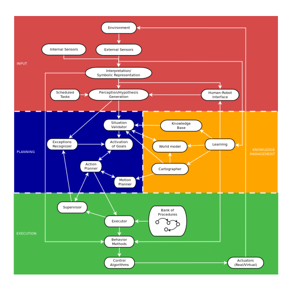
The ViRbot architecture defines a human-robot interaction interface made of three main layers, as seen in figure 1: Input layer, Planning and Knowledge Management layer, and Execution layer.
The Input layer includes all algorithms related to the acquisition of data from the environment.
The Planning and Knowledge Management layer performs most of the AI algorithms.
The Execution layer includes low-level control and supervision.
The implementation of ViRbot is made through several modules (executables) that perform well defined tasks and have a high interaction. The information exchange between modules is made through a central module called Blackboard, which supports shared variables, with publisher/subscriber pattern, and message passing.
Current research
3.1 Cross-platform architecture through a BlackBoard system
BlackBoard (BB) is a message forwarding module that enables communication between different programs through the Resquest-Response schema as Remote Procedure Calls. It is also a repository of shared variables that can be read and written by any module (program) connected to it.
It was developed with C# and the .NET framework, and there are currently APIs to build BB modules for languages C#, C++ and python. It runs on windows and linux-based systems (with the help of Mono, the open source implementation of Microsoft's .NET framework) such as Ubuntu and Raspberrian (as command line interface). Also, a BB module has been developed for an Android system and a CLIPS interpreter has been used with the help of PyCLIPS, expanding the number of platforms and languages available to use with it.
This makes it an ideal platform for integrating software running in different computers and different languages. BB's commands and shared variables have a certain equivalence to ROS's services and topics respectively, so integration between modules working with these platforms has been accomplished through the implementation of a BlackBoard Bridge module, which communicates with both systems.
3.2 Planning using plan-space search and hierarchical task networks
The task planning is implemented as an expert system with logical programming. It adopts concepts from plan-space search planning and hierarchical task networks (HTN).
On the one hand, the task networks would be useful to specify dependencies between tasks that would be difficult to represent with a detailed description of the environment and the effects of actions on it, like the ones used in classical STRIPSlike planners. On the other hand, it uses the plan-space search in order to make planning as objective oriented as possible, so depending on the current situation and the currently active tasks, each task can decompose in one plan or another.
The plan specification is done through facts that represent a hierarchical structure of tasks, and each task can have several planning rules. The planning rules would be useful for considering different situations, present in the environment, so the robot can act accordingly.
A graphical tool for designing the plans was also developed. It uses the formalism of High Level Petri Nets (HLPN) to model the planning rules. Each rule includes one transition that separates its preconditions from its effects. In general, places in the Petri nets diagram would be labeled or named with a syntax that resembles first order logic predicates, and they would correspond with facts about the world or actions to be executed.
3.3 Navigation based on behaviors
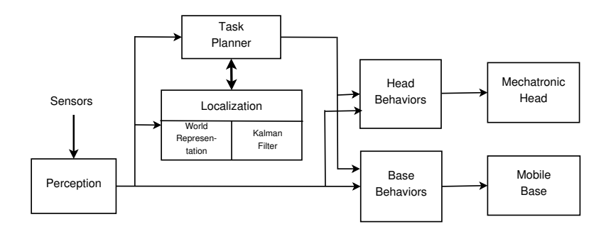
The Navigation system is composed of several subsystems performing different tasks in different levels of abstraction: a task planner, a set of behaviors controlling the mobile base and another set controlling the mechatronic head, a localization subsystem, which contains the world representation and a Kalman filter for estimating the robot's position, and a perception module, responsible for processing the raw sensor data. Figure 2 shows a block diagram of the different subsystems and its connections. Following subsections explain each subsystem and the way they interact.
Justina's perception module includes object and face detection and recognition, natural landmark extraction, speech recognition, detection of obstacles and their position, skeleton detection and proprioception, that includes odometry and position estimations of the head and arms. The navigation system uses the subprocesses of odometry, landmark extraction and obstacle detection.
Landmarks are extracted from laser readings and point clouds generated by the Kinect sensor, using an algorithm based on the work of [2]. Obstacles are extracted from the laser readings and kinect point cloud using K-means algorithm for clustering the non-free space.
World Representation includes a geometric representation of the obstacles in the environment and a set of nodes used for path planning. Such path planning is made using the Dijkstra algorithm, considering information contained in the world representation and the perception module. Localization is made using a Kalman Filter.
The mobile base and the mechatronic head are controlled by a set of behaviours. Head is moved by two behaviors. The first one tries to point the head towards the nearest landmarks and the second one, towards the nearest obstacle.
Mobile base is controlled by three behaviors. First behavior tries to move the robot towards a given goal point. The second one, avoids obstacles using potential fields. Laser readings are used for this purpose. The third behavior is checking if there are obstacles with which the robot could crash and stops the robot in case of collision risk.
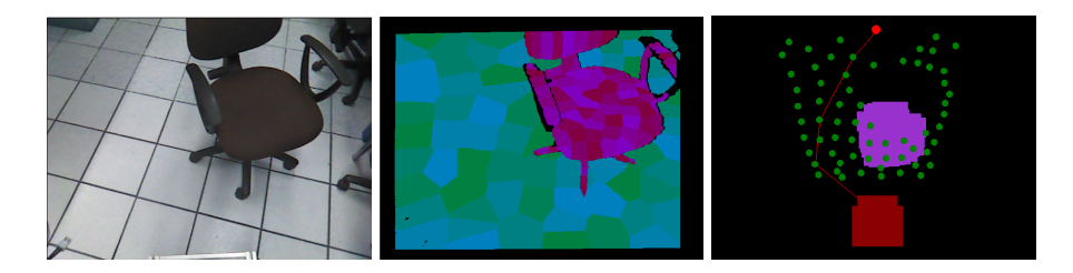
The navigation system also builds roadmaps when it is moving to improve the obstacle avoidance. Roadmaps are constructed following the next steps:
- Point cloud acquisition from the kinect sensor.
- Transformation to the robot frame coordinates.
- Separation of free and occupied space (considering the z-coordinate of the points).
- Clusterization of free and occupied space by vector quantization techniques.
Centroids of free space are taken as nodes to calculate paths and clusters of occupied space are taken as obstacles. See figure 3.
3.4 Heterogeneous computing for point cloud processing
For a service robot, it is crucial to process a big amount of sensor's data in real-time to understand the environment around and react according to it. To achieve this, a device with high computing capabilities and concurrent processes running all the time is needed. Ideally one process for each sensor.
One of the most time consuming tasks in a service robot is the processing and analysis of 3D point clouds, where several thousand of readings per second can be obtained from the sensors.
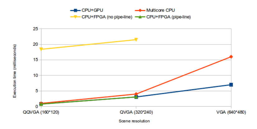
For this reasons, the performance of different algorithms for point cloud processing has been tested using different heterogeneous computing systems. The systems tested are: CPU+GPU, CPU+FPGA, and CPU multicore.
Figure 4 shows an example of the comparison of the execution time for the RANSAC algorithm using different systems. This algorithm is commonly used for plane segmentation in a 3D point set.
3.5 Exploration in Human-Robot Physical Interfaces
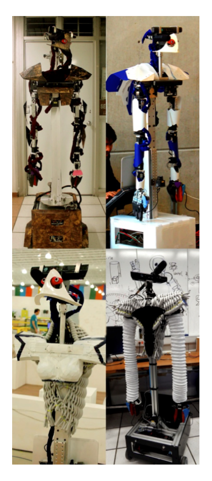
As a physical interface we refer to the covers of the robot, their face, chest, arms and base shells. We have developed four designs with some variations since 2012 to 2015. Our goal is to give a friendly and interesting characterization to the robot that could be easily accepted by users. All of it keeping in minds the kinematic, navigation, tracking and vision features of the robot.
The developed designs have avoided the Uncanny Valley [3], keeping away of mimetical appearance, without losing the basic anthropomorphic structure (bilateral symmetry, upright chest, and two arms).
The robot appearances have four stages at the moment:
Conceptual character. We developed a background story for the robot, giving it a steampunk style. Their shells look like a rusty metal with golden hues, similar to baroque altarpiece. This design had a good acceptance by the youngest people, children expressed scare, and adults looked uncanny. We think that was provoked by the palette, unusual in robots (golden and purple), as well as looking like an old machine.
Minimal character. It preserves almost all the features of the first design (face and shells), but we turned the rusty finish into a minimal white and shiny finish. This one has a general good acceptance because it was neutral. We could emphasize that their face (not human appearance) provoke empathy with users because of the friendly design.
Femme Character. We tried to give some feminine touch inspired in the name of the robot Justina. We 3D-printed a shell that covers the chest, similar to a space suit that preserves the shape of a female breast. It falls immediately in the Uncanny Valley and everyone rejected it, even the other team members.
Revolutionary character. It was made by knitting soft fibres creating a fabric that cover the chest, taking out the face and just fitting the Kinect sensor as a head. In first place the soft materials result the best option because we could get the hardware easily without taking off the shells also it protects the users and the robot in case of accidental collision. In second place taking off the face of the robot decreased a big amount of empathy, and moreover, it contrasts with the anthropomorphic shape.
Giving some character to the robot could bring more acceptance by the people, but it is important to keep in mind that the appearance that we give to the robot defines the way people react. Finally, the experimentation with various materials and processes (3D printing, laser cutting, hand-knitted and artistic finish) let us test different ways to give expressivity to the robot.
Conclusions and future work
The ViRbot system was successfully tested in the Robocup@Home category since the Robocup competition of Atlanta 2007. In these years, the full system has been improved having reliable performance and showing promising results. Also the Blackboard system grants us a versatile platform for developing subsystems, without the restriction of an operating system or a specific programming language.
As future work, algorithms for object and face recognition based on 3D features are being developed. Also, SLAM techniques are being tested using 3D information.
For the manipulation task, a new control algorithm and a path planning system will be implemented for the arms module.
Justina, a general purpose service robot
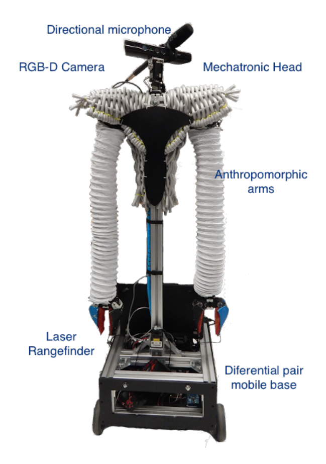
Robot Justina is our entry robot to the RoboCup@Home competition.
Hardware
- Differential pair mobile base (self design)
- Arduino Mega for control.
- Pololu RoboClaw board as motor driver.
- Left and Right Arms:
- Anthropomorphic Design.
- 7 DOF.
- 10 Dynamixel servos.
- CM-700 Microcotroller board for control and path planning.
- Mechatronic Head:
- 2 DOF (Pan and tilt).
- 2 Dynamixel Servos.
Sensors
- RGB-D camera Kinect.
- Laser rangefinder Hokuyo URG-04LX-UG0
- Directional Microphone Rode
Software
Robot Justina uses computers running both Linux and Windows, and modules programmed in C#, C++, Python and CLIPS.
- Action Planner.
- Please refer to 3.2 for a detailed description.
- Simple Task Planner.
- Bank of Procedures that involves simple and repetitive tasks easily achieved by state machines.
- Examples of procedures: grasping an object, searching for a face, aligning with an edge, etc.
- Motion Planner.
- Please refer to 3.3 for a detailed description.
- Object Finder
- Image and point clouds processing
- Object recognition using SIFT [4] + histogram comparison.
- Geometric characteristic extraction of the environment (planes, lines, corners, spikes).
- Person Finder
- Multiple face detection and recognition.
- Using VeriLook SDK (commercial software).
- Speech Recognition
- Strings of hypothesis of recognized voice with confidence ranking.
- Using Microsoft SAPI 5.3 (commercial software).
- Speech Generator
- Voice synthesizer.
- Using Microsoft SAPI 5.3 with the Loquendo Susan voice (commercial software).
References
- Jesus Savage and et al. Virbot: A system for the operation of mobile robots. In Ubbo Visser, Fernando Ribeiro, Takeshi Ohashi, and Frank Dellaert, editors, RoboCup 2007: Robot Soccer World Cup XI, volume 5001 of Lecture Notes in Computer Science, pages 512–519. Springer Berlin Heidelberg, 2008.
- R. Yan, J. Wu, W. Wang, S. Lim, J. Lee, and C. Han. Natural corners extraction algorithm in 2d unknown indoor environment with laser sensor. In Control, Automation and Systems (ICCAS), 2012 12th International Conference on, pages 983–987. IEEE, 2012.
- M. Mori, K.F. MacDorman, and N. Kageki. The uncanny valley [from the field]. Robotics Automation Magazine, IEEE, 19(2):98–100, June 2012.
- David G. Lowe. Distinctive image features from scale-invariant keypoints, 2003.