Tinker@Home 2017 Team Description Paper
Jiacheng Guo, Haotian Yao, Haocheng Ma, Yuan Dong, Yilin Zhu, Jingsong Peng, Xukang Wang, Xiaojian Ma
Future Robotics Club(Group), Tsinghua University, China
http://tinker.furoc.net · https://github.com/tinkerfuroc
Abstract This paper describes our service robot Tinker of Tsinghua University, China, including the mechanical system, hardware system and software system. Tinker is designed to be an autonomous robot in domestic environment, capable of navigating in complicated environment and finishing different tasks, mainly following the rules of @Home League of World RoboCup 2017. This paper introduces both the hardware design of the robot and the algorithms we have proposed and implemented.
1 Introduction
Tinker is developed by FuRoC (Future Robotics Club), which is a student group in Tsinghua University focusing on robotics, AI and related areas. It is our third participation in the @home League of World RoboCup. Tinker is designed to be an autonomous humanoid robot mainly for home service. To complete home service tasks, abilities such as automatic navigation, environment perception, interaction with human, recognizing and carrying small objects, etc, are required. Tinker is equipped with a mobile chassis, a lift platform, a 6-DoF arm, and different kinds of sensors. Depth cameras (Kinect v2 and primesense) are used for imaging and recognizing environment, objects and different user. A laser scanners is used for sensing the surroundings and navigation. Tinker is also equipped with a microphone for hearing and understanding voice orders.
2 Overview of the robot
Tinker system has to deal with challenges at different levels from hardware interface to artificial intelligence. Thus, a multi-level, distributed architecture based on ROS is employed to meet such requirement.
2.1 Overview of the architecture
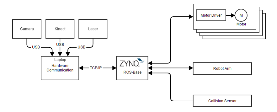
The hardware layer are the motors and the sensors of the robot. The hardwarecommunication layer is responsible for controlling the motors and acquiring information from the sensors. The output of the hardware layer is ROS-compatible sensor images including camera image, point cloud and multiple other topics. The logic layer is responsible for providing basic functions of a robot such as manipulation, navigation, human tracking, object recognition, speech recognition and synthesis etc. The decision layer listens to topics published by the logic layer and makes decision for the next high-level action to make.
The hardware layer
The motors we use are:
- Times Brilliant DMS-055A motors for driving the chassis and the platform
- ALFS ASME-03 high-torque servo for the robot arm
- Dynamixel MX-64 servo for robot hand
The sensors we use are:
- Hokuyo URG04LX laser scanner for navigation
- Kinect v2 depth camera for navigation and object detection
- Logitech C170 camera for object recognition and detection
- Infrared proximity sensor for manipulation
The hardware-communication layer
The hardware communication layer must be highly scalable to quickly install and remove different sensors and executors. All control commands of the robot are sent to the ROS nodes running on the Xilinx ZYNQ soc. The ZYNQ soc then controls the motor peripheral. For sensors, those which already have had a ROS wrap like Kinect, camera and laser scanner are directy connected to the laptop computer while the feedback of motors other senor messages that need further processing to ROS messgaes are sent to ZYNQ, where ROS nodes are running to collect information and tranlate them to ROS messages.
The logic layer
Most important robot functions are implemented in this layer. The main components in this layer include:
- Navigation: Mapping, localization, route-planning and collision avoidance
- Vision: Human recognition, object recognition and their tracking.
- Speech: Speech recognition and synthesis
- Arm control: Manipulation with feedback from vision
The decision layer
Task planning is done in decision layer. For different tasks, modules in decision layer run as state machine. They integrate different information from the low layer to judge the state they are in and then give different orders or make different responses. Each module deal with a single task, sharing the common information from the lower layers.
3 Mechanical Design
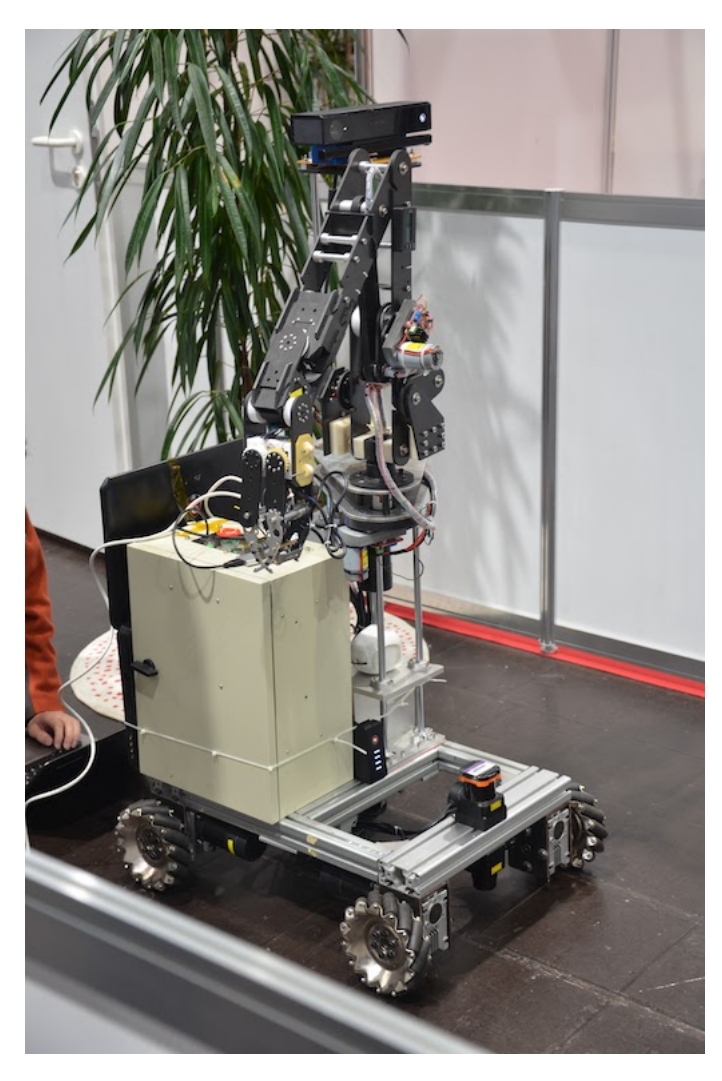
To complete most of home serving tasks, our robot consists of three major parts: chassis based on Mecanum wheel, Ball screw Actuator and robot arm including hand. Tinker is about 150cm in height.
Chassis
Tinker can move in any direction easily owing to the Mecanum chassis. The chassis consists of 4 separated Mecanum wheel systems, each of which consists of a Mecanum wheel, a brushless DC motor (50W24V), a worm gear box and a brush-less DC motor driver. The PC sends control message to the ZYNQ to command the chassis to move as planed based on ROS. The chassis has a size of 800mm × 500mm × 200mm.
Robot arm and hand
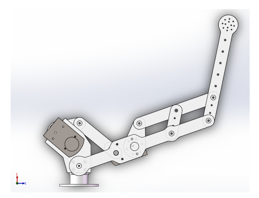
The robot arm is the most major part of the mobile robot, used to grasp objects. The complete arm consists of a 3-axis cascade robot arm and a 2-axis robot hand. The 3-axis arm consists of 2 bent joints and a rotate joint; the 2-axis hand consists of a rotate joint which controls the posture and a joint which achieves grasping objects. We use 24V geared DC motor for the arm and MX-64R (Robotis series) as the steering engines for the hand. The maximum length of the arm is about 800mm and it can grasp a 1000g object at maximum length, which is enough for most household tasks.
Ball screw Actuator
The bottom of the robot arm is fixed on the Ball screw Actuator so that the arm can be raised or lowered freely, quickly and smoothly. The lift platform enables the robot to manipulate objects of various height. Besides, it provides more workspace.
4 Software Engineering
This section covers the software systems and algorithms implemented for Tinker.
4.1 Computer Vision
Computer vision is indispensable for tinker to accomplish multiple tasks including person recognition, object manipulation and environment modeling.
Human Tracking
For human tracking and following, we implemented the TLD (Track-Learning Detection) algorithm. TLD was proposed by Zdenek Kalal and is currently the state-of-art real time tracking algorithm. It combine the traditional tracking and detection algorithm so that it is more robust in consideration of distortion and partial occlusions. TLD algorithm consists of three modules as its name indicated. Tracking module estimate moving direction of the object according to the difference between two adjacent frames. Detection module detect the object in each frame independently. Learning module integrate the results of the tracking module and detection module to correct the detection errors and update the features of the target object. We applied the TLD algorithm to human tracking and following tasks. Before the robot starts following, the human partner to be followed will be asked to stand in front of Kinect and the robot will record his/her features. When the instructor starts moving around, the robot will track and keep up with him. The robot also uses the depth information to keep away from the instructor at a safe distance.
Face Recognition
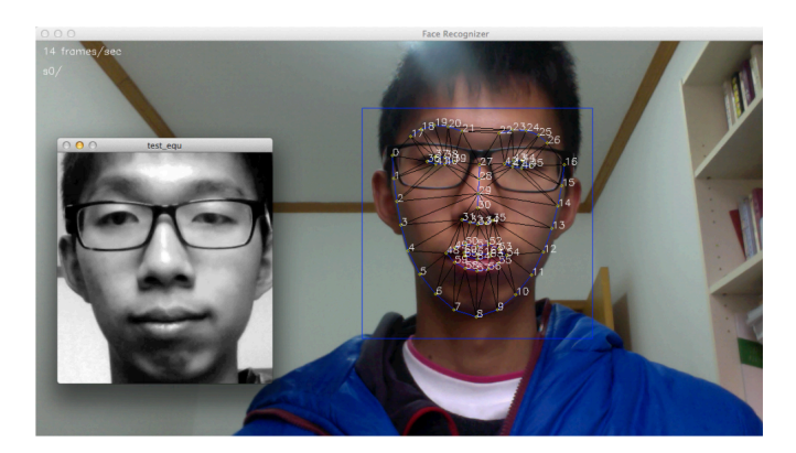
For human-robot interaction, a robot is required to recognize different masters or guests in home service. We developed a face recognition system with two process: enrollment and recognition. During the enrollment process, a man is asked to stand in front of the RGB camera. A face detector based on haar feature from OpenCV is applied and the detected face will be stored. For a single person, the system stores 3-5 pictures. We used face++ API for face detection and implemented the face recognition algorithm based on sparse representation. A redundant dictionary is trained offline using a set of training faces. The algorithm seeks the most sparse representation coefficient by solving a L1 optimization problem. The residual errors for different classes (persons) tell who is the unknown person: if the residual error for a specific class, for example, person A, is smaller than a specified threshold and the errors for other classes are larger than another specified threshold, the newcoming person is identified as person A. More details of this face recognition pipeline can be found in reference [3].
Object recognition
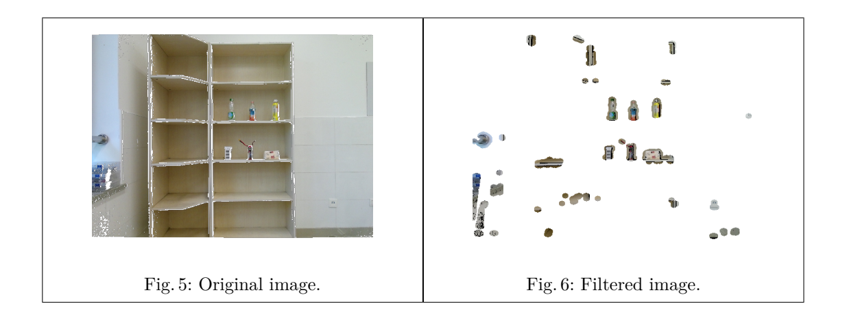
Tinker uses a two-phase approach to recognize objects and precisely manipulate them. In the first phase, a point cloud is built from the Kinect depth camera. Hough transform and an entropy-based filter is applied to the point cloud to remove the backgroud. Then a euclidean clustering will give the region of interest. A typical image of the filtered point cloud is given below:
In the second phase, the approximate location of object is given to the robot arm controller, another usb camera placed in the hand of the robot arm will guide the arm to precisely manipulate the object. First, the hand is moved to directly face the location of the region of interest at about 40 cm away. A similar image processing pipeline is used to find the object in the image given by the camera in hand. After getting the image of the object, it is matched with the pre-captured image set by convolution the image with the templates to find the best match. Precision of the location found in this phase is significantly improved due to a much closer camera place. Then the robot arm will be guided by the camera using a feedback procedure to place the object in the middle of the camera image. Thus, the chance of missing the object is reduced.
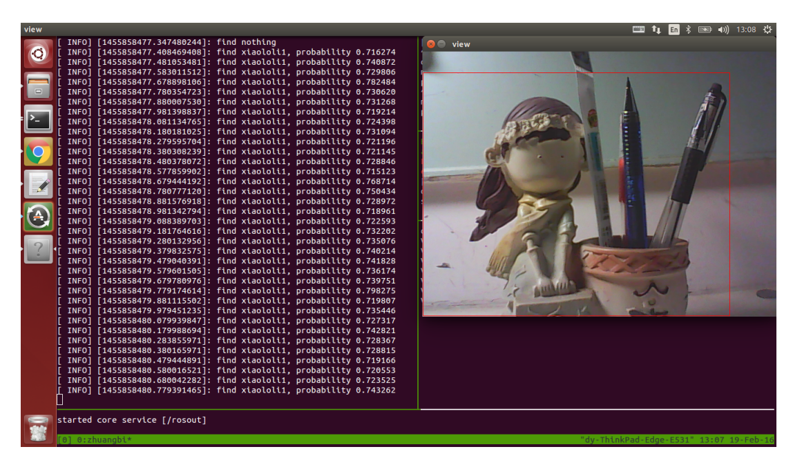
For object classification, another image processing pipeline is implemented. We used YOLO9000 for general object type detection. YOLO9000 is a light-weight while precise nerual network for genral object detection and classification. Then we implemented a bag of words model to pair the object image with those collected in the library.
4.2 Navigation
Navigation is a key capability for an autonomous mobile robot.
Simultaneous Localization and Mapping
SLAM is one of the most important algorithms for a mobile autonomous robot, which enables a robot to navigate and explore in an unknown environment. Mapping requires the robot to record, integrate and update the former information it have got about the surroundings while Localization requires the robot to know the location of itself refer to the estimated environment. Using a laser range finders (LRFs), we adopted the SLAM package to estimate the robots location and its surroundings in the form of 2D occupancy grid map. The raw data from LRFs are collected as the input of the algorithm. Features, or landmarks are then extracted from the environment. When the robot moves around, these features are used to estimate where it moves. It is called Laser-Scan-Matcher process. However, the estimation of this process is imprecise and the error accumulates. The GMapping process is adopted, using an EKF (Extended Kalman Filter) to correct the estimated result. Based on the final map generated, the robot plans its path and explores the unknown environment. We also implemented SLAM using color and depth camera, also called vSLAM, so that a 3D map can be obtained, which is more precise in complicated environment. Building map using vSLAM is still a experimental feature for tinker and needs further refining.
Navigation
Navigation is one of the basic function that a mobile autonomous robot must have. The robot needs to plan the route from its current position to the goal. An A* algorithm is used to find the route considering both distance and collision avoidance. Moreover, the robot must be able to handle unexpected obstacles when moving around. The navigation package is applied and modified for the tinker robot. Parameters in the move_base package are tuned and the navigation task can be achieved functionally but the behavior and speed is far from satisfactory. We extended a local which subscribes the origin global plan and linearizes the curve. In this way, the whole processing could be more fluently. To avoid small objects and non cylinder-like objects like chairs and cups on the floor, we use depth cameras including a kinect2 and a primesense to build another local obstacle layer. Since pointcloud tend to be noisy, we filter this obstacle layer to achieve more stable navigation performance.
4.3 Speech Recognition
Natural Language understanding provides a convenient way to interact with a robot. Currently, we apply the CMU Sphinx package for speech recognition. We update the keywords database by adding necessary words and phrases for understanding different orders and compile it into a library file. When the software recognizes a sequence of special keywords, the robot interprets one's intention and makes corresponding responses. For sound localization, we use the inner-build microphone array in kinect.
5 Team repository
Our team repository can be found at https://github.com/tinkerfuroc. The repository may be of help to other teams by providing:
- Implementation of all the algorithms and needed parameters described in the paper
- Robot setup scripts and tools
- Code for RoboCup@Home tasks
6 3rd Party Dependencies
The following third-party dependencies are used:
- ROS
- ROS Navigation Stack
- iai_kinect2
- darknet (YOLO9000)
- tensorflow
- face++ Face API
Acknowledgement
The authors of this paper would like to thank previous team members of Tinker@Home 2014 and Tinker@Home2015 for their help and support through out building the robot and writing this manuscript. The authors would also like to thank Seagate and DJI for their funding.
References
- Z. Kalal, K. Mikolajczyk, and J. Matas, "Tracking-learning-detection," Pattern Analysis and Machine Intelligence, IEEE Transactions on, vol. 34, no. 7, pp. 1409–1422, 2012.
- J. Wright, A. Y. Yang, A. Ganesh, S. S. Sastry, and Y. Ma, "Robust face recognition via sparse representation," Pattern Analysis and Machine Intelligence, IEEE Transactions on, vol. 31, no. 2, pp. 210–227, 2009.
- F. Xia, L. Tyoan, Z. Yang, I. Uzoije, G. Zhang, and P. A. Vela, "Human-aware mobile robot exploration and motion planner," in SoutheastCon 2015. IEEE, 2015, pp. 1–4.
- J. Redmon and A. Farhadi, "Yolo9000: Better, faster, stronger," 2016.
- G. Csurka, C. Dance, L. Fan, J. Willamowski, and C. Bray, "Visual categorization with bags of keypoints," in Workshop on statistical learning in computer vision, ECCV, vol. 1, no. 1-22. Prague, 2004, pp. 1–2.
- G. Grisetti, C. Stachniss, and W. Burgard, "Improved techniques for grid mapping with raoblackwellized particle filters," Robotics, IEEE Transactions on, vol. 23, no. 1, pp. 34–46, 2007.
- S. Se, D. G. Lowe, and J. J. Little, "Vision-based global localization and mapping for mobile robots," Robotics, IEEE Transactions on, vol. 21, no. 3, pp. 364–375, 2005.
- P. Lamere, P. Kwok, E. Gouvea, B. Raj, R. Singh, W. Walker, M. Warmuth, and P. Wolf, "The cmu sphinx-4 speech recognition system," in IEEE Intl. Conf. on Acoustics, Speech and Signal Processing (ICASSP 2003), Hong Kong, vol. 1. Citeseer, 2003, pp. 2–5.