Tech United Eindhoven @Home 2018 Team Description Paper
M.F.B. van der Burgh, J.J.M. Lunenburg, R.P.W. Appeldoorn, R.W.J. Wijnands, T.T.G. Clephas, M.J.J. Baeten, L.L.A.M. van Beek, R.A. Ottervanger, S. Aleksandrov, T. Assman, K. Dang, J. Geijsberts, L.G.L. Janssen, H.W.A.M. van Rooy, A.T. Hofkamp, M.J.G. van de Molengraft
Eindhoven University of Technology, Den Dolech 2, P.O. Box 513, 5600 MB Eindhoven, The Netherlands
http://www.techunited.nl · https://github.com/tue-robotics · https://github.com/tue-robotics/ed_localization · https://github.com/tue-robotics/ed_navigation · https://github.com/tue-robotics/cb_base_navigation · https://github.com/tue-robotics/ed_perception · https://github.com/tue-robotics/image_recognition · https://github.com/CMU-Perceptual-Computing-Lab/openpose · https://creator.matrix.one · https://github.com/tue-robotics/matrix-creator-hal · https://github.com/tue-robotics/matrix_creator_ros · https://github.com/tue-robotics/tue_mobile_ui · https://github.com/tue-robotics/robot-api · http://www.roboticopenplatform.org/ · https://www.facebook.com/techunited · https://www.youtube.com/user/TechUnited · https://www.twitter.com/TechUnited · https://www.flickr.com/photos/techunited/ · https://www.tyroremotes.nl · https://www.apple.com · https://skybiometry.com/
Abstract This paper provides an overview of the main developments of the Tech United Eindhoven RoboCup@Home team. Tech United uses an advanced world modeling representation system called the Environment Descriptor that allows straightforward implementation of localization, navigation, exploration, object detection & recognition, object manipulation and robot-robot cooperation skills. Recent developments are improved object and people detection via deep learning methods, a generic GUI for different user levels, improved speech recognition, improved natural language interpretation and sound source localization.
1 Introduction
Tech United Eindhoven is the RoboCup student team of Eindhoven University of Technology that (since 2005) successfully competes in the robot soccer Middle Size League (MSL) and later (2011) also joined the ambitious @Home League. The Tech United @Home team is the vice World champion of RoboCup 2017 in Nagoya, Japan and the vice European champion of the 2017 RoboCup German Open. The robot soccer middle-size Tech United team has an even more impressive track record with three world championship titles. See the Tech United website for more results. Tech United Eindhoven consists of (former) PhD and MSc. students and staff members from different departments within the Eindhoven University of Technology.
This Team Description Paper is part of the qualification package for RoboCup 2018 in Montreal, Canada and describes the current status of the @Home activities of Tech United Eindhoven.
2 Environment Descriptor (ED)
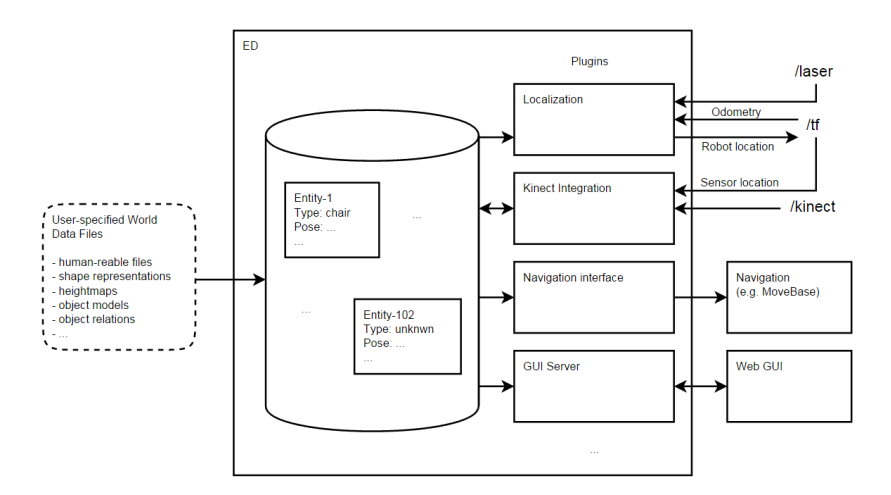
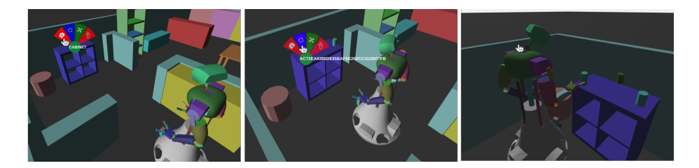
The TUe Environment Descriptor (ED) is a Robot Operating System (ROS) based 3D geometric, object-based world representation system for robots. In itself ED is a database system that structures multi-modal sensor information and represents this in an object-based world representation that can be utilized for robot localisation, navigation, manipulation and interaction functions. Figure 1 shows a schematic overview of ED. ED is used on our robots AMIGO and SERGIO in the open @Home league and will be used on the Toyota HSR in the DSPL league. In previous years, developments have been focussed on making ED platform independent. As a result ED has been used on the PR2 system, Turtlebot and Dr. Robot systems (X80). ED is a single re-usable environment description that can be used for a multitude of desired functionalities instead of having different environment representations for localization, Adaptive Monte Carlo Localization (AMCL), navigation (MoveBase), manipulation (MoveIt!), interaction, etc.. An improvement in this single, central world model will reflect in the performances of the separate robot capabilities. It omits updating and synchronization of multiple world models. At the moment different ED plugins exist that enable robots to localize themselves, update positions of known objects based on recent sensor data, segment and store newly encountered objects and visualize all this through a web-based GUI, illustrated in Figure 7.
2.1 Localization, Navigation and Exploration
The ed localization plugin implements AMCL based on a 2D render from the central world model. In order to navigate, a model of the environment is required. This model is stored in the ED. From this model, a planning representation is derived that enables using the model of the environment for navigation purposes. With use of the ed navigation plugin, an occupancy grid is derived from the world model and published as a nav msgs/OccupancyGrid. This grid can be used by a motion planner to perform searches in the configuration space of the robot.
With the use of the cb base navigation ROS package the robots are able to deal with end goal constraints. With use of a ROS service, provided by the ed navigation plugin, an end goal constraint can be constructed w.r.t. a specific world model entity described by ED. This enables the robot to not only navigate to poses but also to areas or entities in the scene. Somewhat modified versions of the local and global ROS planners available within move base are used.
2.2 Object detection
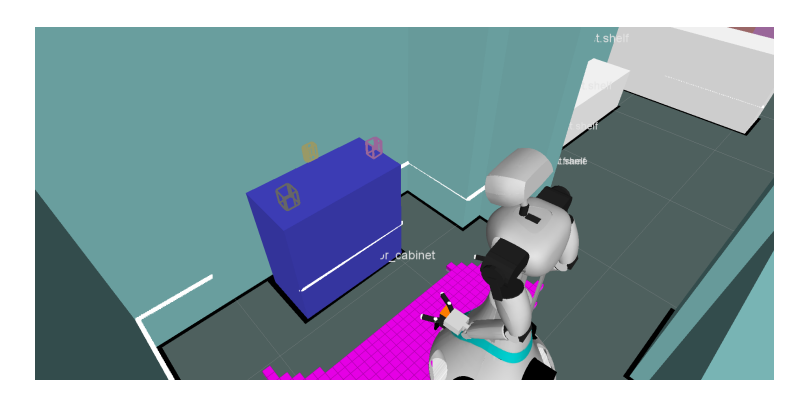
Detection & Segmentation. ED enables integrating sensors through the use of the plugins present in the ed sensor integration package. Two different plugins exist: 1. The laser plugin: Enables tracking of 2D laser clusters. This plugin can be used to track dynamic obstacles such as humans. 2. The kinect plugin: Enables world model updates with use of data from the Microsoft KinectTM. This plugin exposes several ROS services that realize different functionalities:
- (a) Segment: A service that segments sensor data that is not associated with other world model entities. Segmentation areas can be specified per entity in the scene. This allows to segment object 'on-top-of' or 'in' a cabinet.
- (b) FitModel: A service that fits the specified model in the sensor data of the Microsoft KinectTM. This allows updating semi-static obstacles such as tables and chairs.
The ed sensor integration plugins enable updating and creating entities. However, new entities are classified as unknown entities.
2.3 Object grasping, moving and placing
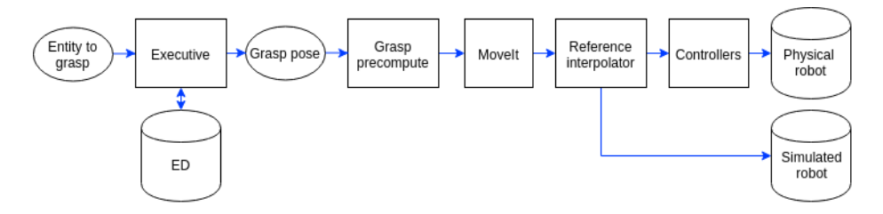
As for manipulating objects, the architecture is only focused on grasping. The input is the specific target entity in the world model ED. The output is the grasp motion, i.e. joint positions for all joints in the kinematic chain over time. Figure 3 shows the grasping pipeline. A python executive queries the current pose of the entity from ED. The resulting grasp pose goes to the grasp precompute component which makes sure that the object is approached in a proper way. MoveIt will produce joint trajectories over time with use of the current configuration, the URDF model and the final configuration. Note that MoveIt currently does not take any information from ED into account. This is planned to be implemented before RoboCup. Finally, the trajectories are sent to the reference interpolator which sends the trajectories either to the controllers or the simulated robot.
The grasping pipeline is extended with an empty spot designator and grasping point determination. The empty spot designator searches in an area for an empty spot to place an object by using the occupied area by other objects in this area.
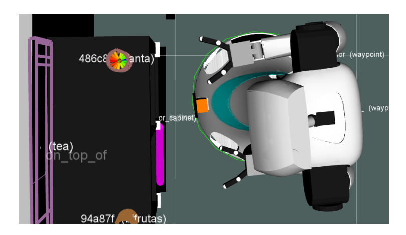
The grasp point determination uses the information about the position and shape of the object in ED to determine the best grasping point. The grasping point is a vector relative to the robot. An example of the determined grasping point is shown in Figure 4.
3 Image Recognition
In order the classify or train unknown entities, the ed perception plugin exposes ROS services to classify the entities in the world model. The ed perception module interfaces with various image recognition nodes that apply state of the art image classification techniques based on Convolution Neural Networks (CNN).
3.1 Object recognition using Deep Learning
Object recognition is done using Tensorflow by retraining the top-layer of a Inception V3 neural network. The top layers are retrained on a custom dataset using a soft-max top-layer that maps the image representation on a specified set of labels.
In order to create a new training set for specific objects, the ed perception and the image recognition packages contain several tools for segmenting and annotating objects. Tools for retraining neural networks are included.
3.2 Face recognition
Face detection and recognition is done using OpenFace based on Torch. Open-Face is an existing state-of-the-art face recognition library. We implemented a ROS node that enables the use of these advanced technologies within the ROS network.
3.3 ROS packages
Our image recognition ROS packages can be found on GitHub together with tutorials and documentation. Recently, they have also been added to the ROS Kinetic package list and can be installed as Debian packages:
r o s−k i n e t i c −image−r e c o g n i t i o n
4 Pose detection
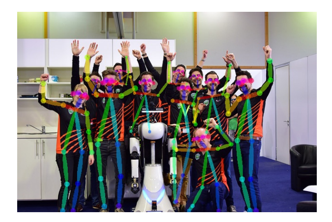
Pose detection is done with OpenPose. OpenPose is a real-time multi-person keypoint detection library for body, face, and hands. It's used for example in the restaurant challenge to detect waving persons. In the finals we used it to detect when an operator points to objects in the living room. For that we ray-traced the vector of the arm in our world model and extracted the first object that the ray intersects. This enables the robot to understand commands like: "Give me that object". See figure 5 for an example of the output of the algorithm.
5 Sound source localization
To perform proper speech recognition, knowing the direction of the sound is important to capture the sound source properly. We localize the sound source by determining the direction of arrival (DOA) with use of the microphone array board with 8 microphones of the Matrix Creator. The detection is done by first calculating the time cross correlation between four pairs of opposing microphones. Second, the microphone pair with the lowest phase shift w.r.t. the opposing microphone is selected as being perpendicular to the source. Finally, the direction of the source can be determined by combining this information with the energy level of the microphones. Our software for the DOA detection is available on GitHub, as well as a ROS package that exposes the DOA detections via a geometry msgs/PoseStamped topic interface.
6 Human-Robot Interface
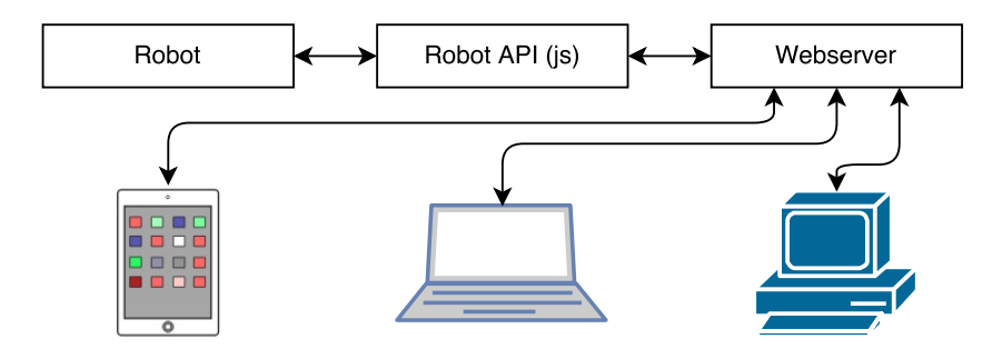
In order to interact with the robot aside from speech, a web-based Graphical User Interface (GUI) has been designed. The interface uses HTML5 and is hosted on the robot itself. This allows multiple users on different platforms (e.g. Android, iOS) to access functionality of the robot. The interface is implemented in JavaScript with AngularJS and it offers a graphical interface to the Robot API which exposes all the functionality of the robot. Figure 6 gives an overview of the connections between these components. Figure 7 gives an example of various user interactions that are possible with the GUI and the different commands that can be given to the robot while interacting with the virtual scene.
6.1 Re-usability of the system for other research groups
Tech United takes great pride in creating and maintaining open-source software and hardware to accelerate innovation. Tech United initiated the Robotic Open Platform website, to share hardware designs. All packages include documentation and tutorials. Tech United and its scientific staff have the capacity to co-develop (15+ people), maintain and assist in resolving questions.
6.2 Community Outreach and Media
The Tech United team carries out many promotional activities for children to promote technology and innovation. These activities are performed by separate teams of student assistants. Tech United often visits primary and secondary schools, public events, trade fairs and has regular TV appearances. In 2015 and 2016 combined, 100+ demos were given and an estimated 50k people were reached through live interaction. Tech United also has a very active website, and interacts on many social media like: Facebook, YouTube, Twitter and Flickr. Our robotics videos are often shared on the IEEE video Friday website.
Amigo's Hardware Description
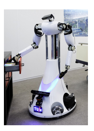
AMIGO (Autonomous Mate for Intelligent Operations, see Fig. 8) has competed in RoboCup@Home since 2011. Its design is based on a Middle Size League soccer robot, equipped with two PhilipsTM Experimental Robotic Arms mounted on an extensible upper body. Based on our experiences with AMIGO, SERGIO (Second Edition Robot for Generic Indoor Operations, has been developed. The main differences with AMIGO are the use of Mecanum wheels which are compliantly suspended, the torso with two degrees of freedom and the modular setup. The core specifications of AMIGO are shown in Table 1. More details about the robots are on the Robotic Open Platform, where all CAD drawings, electrical schematics and CAD files are published. SERGIO will not enter the competition this year.
Core specifications of AMIGO
| AMIGO | |
|---|---|
| Name | Autonomous Mate for IntelliGent Operations |
| Base | Fully holonomic omni-wheel platform |
| Torso | 1 vertical DoF using a ball screw |
| Manipulators | 2 7-DoF PhilipsTM Experimental Robotic Arms |
| Neck | Pan-tilt unit using two Dynamixel RX-64 servo actuators |
| Head | KinectTM Microsoft for XBox 360TM |
| External devices | Wireless emergency button |
| Dimensions | Diameter: 0.75 m, height: ±1.5 m |
| Weight | ±84 kg |
| Additional sensors | Hokuyo UTM-30LX laser range finder on base and torso |
| Microphone | RØDE Videomic and Matrix Creator |
| Batteries | 4× Makita 24 V, 3.3 Ah |
| Computers | 3× AOpen Mini PC with Core i7 processor and 8 GB RAM and NVidia Jetson TX2 |
AMIGO's Software Description
An overview of the software used by the Tech United Eindhoven @Home robots is shown in Table 2. All our software is developed open-source on GitHub.
Some image recognition packages are released into the ROS Kinetic distribution and can be installed with use of apt.
Software overview of Amigo.
| Component | Details |
|---|---|
| Operating system | Ubuntu 16.04 LTS Server |
| Middleware | ROS Kinetic [1] |
| Low-level control software | Orocos Real-Time Toolkit [2] https://github.com/tue-robotics/rtt_control_components |
| Simulation | Custom kinematics + sensor simulator https://github.com/tue-robotics/fast_simulator |
| World model | Environment Descriptor (ED), custom https://github.com/tue-robotics/ed |
| Localization | Monte Carlo [3] using Environment Descriptor (ED), custom https://github.com/tue-robotics/ed_localization |
| SLAM | Gmapping package http://wiki.ros.org/gmapping |
| Navigation | CB Base navigation https://github.com/tue-robotics/cb_base_navigation Global: custom A* planner Local: modified ROS DWA [4] |
| Arm navigation | Custom implementation using MoveIt and Orocos KDL https://github.com/tue-robotics/tue_manipulation |
| Object recognition | Tensorflow ROS https://github.com/tue-robotics/image_recognition/tree/master/tensorflow_ros |
| People detection | Custom implementation using contour matching https://github.com/tue-robotics/ed_perception |
| Face detection & recognition | Openface ROS https://github.com/tue-robotics/image_recognition/tree/master/openface_ros |
| Speech recognition | Dragonfly + WindowsTM Speech Recognition https://github.com/tue-robotics/dragonfly_speech_recognition |
| Speech synthesis | PhilipsTM Text-to-Speech |
| Task executors | SMACH https://github.com/tue-robotics/tue_robocup |
External Devices
AMIGO relies on the following external hardware:
- Tyro 2-channel wireless emergency stop (https://www.tyroremotes.nl)
- Apple iPad for the web GUI (https://www.apple.com)
Cloud Services
AMIGO connects the following cloud services:
– Skybiometry face detection (https://skybiometry.com/)
References
- Morgan Quigley, Ken Conley, Brian P. Gerkey, Josh Faust, Tully Foote, Jeremy Leibs, Rob Wheeler, and Andrew Y. Ng. ROS: an open-source robot operating system. In ICRA Workshop on Open Source Software, 2009.
- H. Bruyninckx. Open robot control software: the orocos project. In Proceedings of the 2001 IEEE International Conference on Robotics & Automation, 2001.
- D. Fox. Adapting the sample size in particle filters through kld-sampling. The International Journal of Robotics Research, 22(12):985–1003, 2003.
- D. Fox, W. Burgard, and S. Thrun. The dynamic window approach to collision avoidance. IEEE Magazine on Robotics & Automation, 4(1):23–33, 1997.