Team Description Paper 2018 Team AutonOHM
Jon Martin, Helmut Engelhardt, Tobias Fink, Marco Masannek, Tobias Scholz
University of Applied Sciences Nuremberg Georg-Simon-Ohm, Kesslerplatz 12, 90489 Nuremberg, Germany
Abstract This team description paper presents the team AutonOHM which won the RoboCup@Work world cup competition in 2017. Detailed description of their hardware and software concepts are presented. The software section introduces the adopted solutions for the @work navigation, perception and manipulation tasks. Furthermore, improvements for future participation in the RoboCup world cup in Montreal 2018 are discussed.
1 Introduction
The RoboCup@Work league, established in 2012, focuses on the use of mobile manipulators and their integration with automation equipment for performing industrial-relevant tasks [3]. This paper presents the AutonOHM teams hardware and software approaches. This year the team focuses on improving the gripper to grasp heavier objects and increasing the robustness and velocity of the system by implementing more intelligent recovery behaviors and reactions to sensor feedbacks. This year remarkable changes have been introduces to the league such as JM: introduce changes ones defined
Chapter 3 shows the team's hardware concept. In chapter 4 the main software modules such as the state machine, localization and object detection are presented. Finally, the conclusion provides a prospect to further work of team AutonOHM (chapter 5).
2 AutonOHM
The AutonOHM-@Work team at the University of Applied Sciences Nuremberg Georg-Simon-Ohm was founded in September 2014. The team consists of Bachelor and Master students, supervised by a research assistant.
AutonOHM participated for the first time in the German Open 2015 tournament. In 2016 the team continued improving their system and competed in the RoboCup@Work world championship in Leipzig and in the European Robotics League in Bonn showing remarkable progress within the tournaments ranking and the robot performance. In 2017 additional team members joint AutonOHM to improve the hardware and implement new functions on the robot. Thus new software approaches in the field of arm kinematics and grasping moving objects were developed. With the improvements of the former and new team members, team AutonOHM reached by a wide margin the 1st place in the German Open 2017 competition in Magdeburg. Even though the robot showed a great performance, many points were lost, as the current gripper was not able to grasp heavy and small objects.
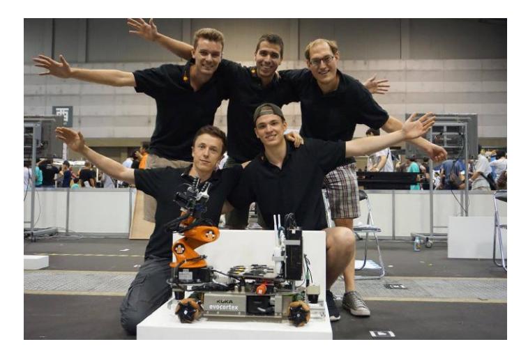
Thanks to their new "German champions" title, the team received the economical support that allowed them to participate in the World Championship 2017 in Nagoya, Japan. To trespass their own result and take the chance to win at Nagoya, a new hardware approach of the gripper has been developed to overcome existing problems. This improvement allowed team AutonOHM (see Fig. 1) to grasp nearly every object without any problems. As a result, the World Championship has been won and the points of the German Open competition have been exceeded.
3 Hardware Description
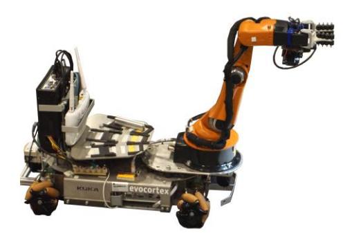
We use the KUKA omni directional mobile platform youBot (Figure 2), as it provides a hardware setup almost ready to take part in the competition. At the end effector of the manipulator, an Intel RealSense 3D SR300 camera has been mounted for detecting objects. This 3D camera has been chosen due to its ability to provide a 3D point cloud in short distances. Next to the camera, the standard gripper is replaced by an own developed, two-finger gripper. Basis is a motor mount for two Dynamixel servos provided by the team b-it-bots1. Two 3D printed fingers with soft rubber wheels are attached to the motors. The gripper allows grasping bigger, heavier and more complex objects than the standard YouBot gripper. Unfortunately we still have difficulties to grasp small and flat objects such as the distance tube.
Two laser scanners, one at the front and one at the back of the youBot platform, are used for localization, navigation and obstacle avoidance. The youBot's default Intel Atom computer has been replaced with an external Intel Core i7-4790K computer, providing more computing power for intensive tasks like 3D point cloud processing. Table 1 shows our hardware specifications.
Tab. 1. Hardware Specifications
| PC 1 | |
|---|---|
| CPU | Intel i7-4790K |
| RAM | 16 GB DDR3 |
| OS | Ubuntu 14.04 |
| Gripper | |
| Type | 3D printed, two-finger |
| Motors | Dynamixel AX-12A |
| Sensors | |
| Lidar Front | SICK TiM571 |
| Lidar Back | SICK TiM571 |
| Camera | Intel RealSense SR300 |
4 Software Description
We use different open source software packages to compete in the contests. Image processing is handled with OpenCV library (2D image processing and object recognition) and PCL (3D image processing). For mapping and navigation we use gmapping and navigation-stack ROS-packages2. Additionally robot-pose-ekf package is used for fusing the data from the IMU and the wheel encoders, to provide more accurate data to the navigation and localization system.
The main packages we developed are further explained in the following sections. These include the state machine (chapter 4.1), modules for global localization, localization in front of service areas (chapter 4.2) and packages for object detection (chapter 4.3) and manipulation (chapter 4.4). As a new feature for the RoboCup 2017 German Open contest, we developed a module for grasping moving objects (chapter 4.5).
Furthermore, there are other small packages including:
task planner: After the task list is received from the referee box, the best route is calculated considering the maximum transport capacity and distances between the workstations.
youbot inventory: With youbot inventory it is possible to save and reuse destination locations, workstation heights and laser data.
4.1 Mission planning
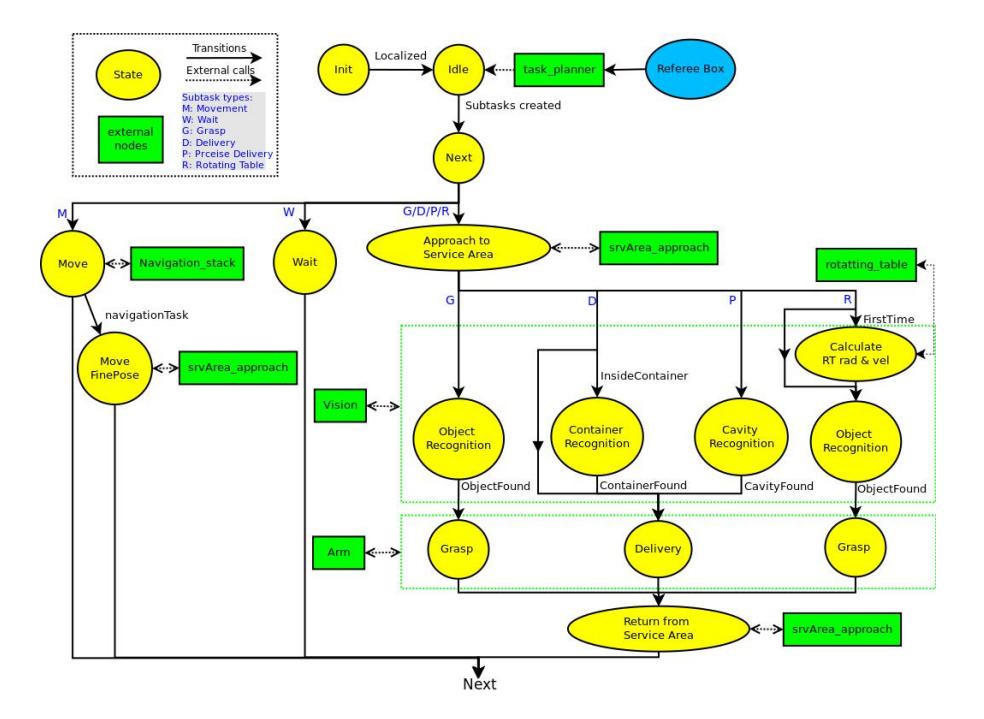
For the main control of the system, a state machine with a singleton pattern design has been developed (figure 2). In the initialization state, the robot receives the map, localizes itself on it and waits in "stateIdle" for new tasks to perform. These tasks are supplied by the referee box, processed by the task planner node and sent to the state machine divided into a vector of smaller subtasks. The subtasks Move, Wait, Grasp, Delivery, PreciseDelivery and RotatingTable are now managed in the "stateNext".
The first step for each task is always to Move (navigate) to a specific position. Depending on the accuracy on the localization, the robot may execute a fine localization, which is explained in section 4.2 and performed by the service area approach node. During a navigation test, once the location is reached, the robot needs to Wait on its position for a defined time before facing the next navigation goal. During the manipulation and transportation tasks, after the specific work station location is reached, the robot may look for specific object, container or cavity on the workstation. In case of a Grasp subtask, the exact pose of the desired object is identified. For Delivering an object, the robot may first need to recognize the exact pose of containers or cavities for PreciseDelivery. Once the desired pose is located, the arm manipulation is activated, whether for picking up and storing the object on the robot or for delivering it. The vision and arm nodes are explained in sections 4.3 and 4.4 respectively. In case of a RotatingTable subtask, before searching for an object, a preprocessing approach must be performed. Here the velocity and the movement radius of the objects are calculated. The rotating table approach is explained in section 4.5. Once the manipulation subtask is finished, the robot moves away from the service area and returns to the "stateNext" that will manage the following subtask to do.
Even if it is not shown in the image, most of the states have error handling behaviors that manage recovery actions in case a navigation goal is not reachable, an object cannot be found or a grasping was unsuccessful. It is very important to notice these failures and react to them by repeating the action or triggering planning modifications. If an object has not been grasped for example, it is not necessary to deliver it and therefore a task planner reconfiguration is required.
The state machine framework can be found on GitHub under our laboratory's repository.3
4.2 Localization
For localization in the arena, we use our own particle filter algorithm. Its functionality is close to amcl localization, as described in [1] and [4]. The algorithm is capable of using two laser scanners and an omnidirectional movement model. Due to the Monte Carlo filtering approach, our localization is robust and accurate enough to provide useful positioning data to the navigation system. Positioning error with our particle filter is about 6 cm, depending on the complexity and speed of the actual movement.
For more accurate positioning, such as approximation to service areas and moving left and right to find the objects on them, we use an approach based on the front laser scanner data. Initially, the robot is positioned by means of the particle filter localization and ROS navigation. If the service area is not visible in the laser scan due to its small height, the robot is moved to the destination pose using particle filter localization and two separate controllers for x and y movement. If the service area is high enough, RANSAC algorithm [2] is used to detect the workstation in the laser scan. Out of this, the distance and angle relative to the area are computed. Using this information, the robot moves in a constant distance along the workstation. We achieved a mean positioning error of under 3 cm during a navigation benchmark tests performed in the European Robotics League local tournament in Milan.
4.3 Object Detection
To grasp objects reliably, a stable object recognition is required. For this purpose, an Intel R RealSenseTM D435 RGB-D camera is used.
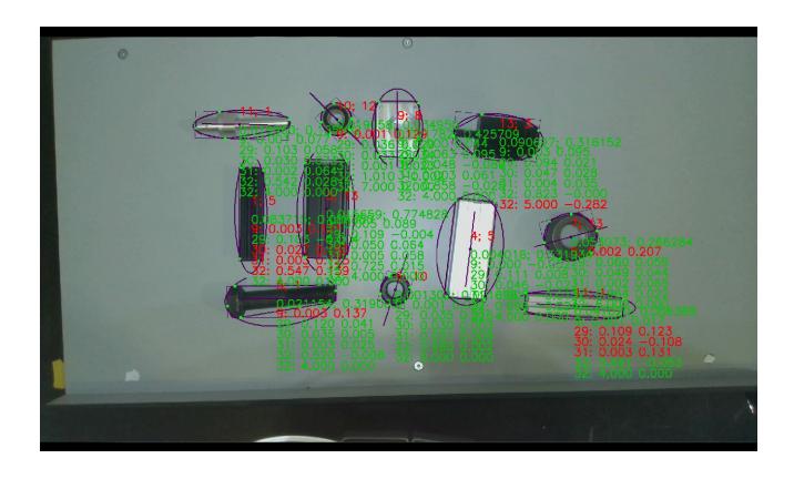
Firstly, the robot navigates to a pregrasp position. Once the base reaches this position, the arm is positioned above the service area. Due to the limited field of view, the robot base moves right and left so all the objects in the workstation can be discovered. On each position, the plane of the service area is searched in the point cloud using the RANSAC algorithm. The detected points are then projected to the 2D RGB image and used as a mask to segment the objects in the 2D image. As all workstations have a white surface, the canny edge detector is used in order to find the concave border of the object in the segmented images for a more accurate result. To classify an object, the following features are extracted: length, width, area, circle factor, corners count, height and black area. With the help of a kNN classifier and the extracted features, the similarity to each previously trained item is calculated. With this information and the inventory information from the referee box, the best possible fitting combination for the detected object on the workstation is searched. To estimate the location of the object, its mass center is calculated. For the rotation of the object, the main axis of inertia is computed and used. The robot will now move in front of the elected object and activate the object recognition again to obtain a more accurate gripping pose. For the new introduced challenge of unknown orientation of the objects this year, the objects get trained from all orientations and the corresponding height will be returned on detection for correct grasping.
4.4 Object Manipulation
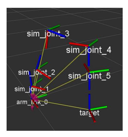
JM: Introduce the placement of standing objects on the delivery platform. The Object Detection node publishes its result as a coordinate transformation represented in figure 4 as "target". The arm controller transforms the target's pose into the arm's workspace and calculates the corresponding joint angles with a self developed solution for the inverse kinematics: Starting with the TCP pointing orthogonally on the target position, the number of solutions is limited by the arm's specifications. Therefore, the 3D equations can be broken down to simple 2D calculations and the law of cosines.
After validating the results, the arm controller calls an interface function of the KUKA youbot drivers to set the target angles, which then move the joint motors with the internal control parameters.
To increase the precision in narrow environments and complex tasks such as grasping or precise placement, the steps between two positions can be interpolated for pseudo-linear movements. Currently the trajectory is followed point to point, but we are developing the trajectory generation for the driver interface to achieve smoother and also more precise motions.
The gripper interface is provided by a microcontroller board which connects the main computer with the two servo motors via serial connections. The communication protocol for the Dynamixels enables us to set predefined positions by sending target angles and also to receive feedback data. With repeated gripper status checks, the arm controller is able to notice if objects are grasped or lost during motions and can therefore react accordingly.
4.5 Rotating Turntable
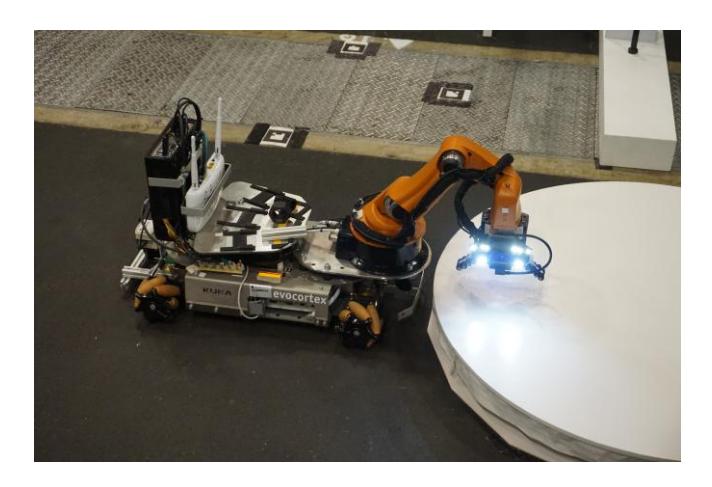
JM: Introduce the changes and the new approach In this task, the robot needs to grasp three objects in motion, which are placed on a rotating turntable. Currently the direction of rotation of the table is fixed and the speed is set by the referees before this competition starts. Object position and orientation on the table can be chosen by the team themselves. The following algorithm considers various parameters such as the rotation speed, rotating direction and the pose of each object on the table.
The robot first navigates to the rotating turntable and extends the manipulator arm to an object detection position. Only performed once, a preprocessing approach is started to obtain the adjusted speed, the direction of rotation and object pose. At first, an object recognition of the first recognized item is executed to collect the 2D position of the circular path. With the collected data points, a RANSAC [2] based algorithm calculates the center and the radius of this path. Having all necessary circle properties, the robot is then able to estimate the rotation speed of the table. Since the pose of the objects can be selected by the team, all objects share the same radius. Therefore, the manipulator is extended to a search and grasp position, adjusted to the calculated results.
As an improvement for the World Championship in Nagoya, we attached a small RGB camera on top of the manipulator. With this extension, we were able to further improve the reliability of our algorithm and to reduce the execution time of the entire task. A simple background change algorithm is now applied to detect the object entrance in the camera view and the previously calculated velocity is used to close the gripper at the right time. With the implemented feedback of the gripper the robot recognizes, whether grasping was successful or has failed. In case of success, the object is placed on the robot and the manipulator then returns back to its previously search position to grasp the remaining objects. If the grasping fails, the manipulator stays in the position and waits for a new object recognition.
As the object pose on the table can be chosen by the teams and the rotation speed of the turntable is having a minor variance, we decided to place all objects on a defined radius. The manipulator pose was adjusted to this radius above the table. With usage of the background change recognition and a random delay for closing the gripper, we were able to grasp all objects. This simplification of our existing algorithm was used to be faster and to obtain more points in the competition.
5 Conclusion and Future Work
This paper described the participation of team AutonOHM in the RoboCup@work league. It provided detailed information of the hardware setup and software modules like localization, autonomy, image processing and object manipulation.
JM: review it all together at the end. Introduce the main changes: Due to several changes in this years rulebook, we plan to adapt and improve our existing robot in different fields. JM: @Helmut: The perception must be trained to detect now the objects in lying and standing positions. JM: @Marco: The new manipulator approach, must now reliably place standing objects in its platform. JM: @Scholz: An additional RGB camera has been attached on the manipulator to update our existing rotating turntable algorithm and increase its reliability. Furthermore, minor corrections have been done in the navigation and object detection approaches to reduce the execution time of each task.
In order to further improve the robot's capabilities, our main priorities for the future are: Develop a new energy concept for a longer run-time of the Youbot platform; Improve our log and recovery system by increasing the feedbacks from different sensors such as the gripper, laser scanners and camera. Finally, as the Youbot has been discontinued, we started developing a new mobile platform that will be shorter for a better navigation performance and that integrates optimal place for the new energy concept and computer (NUC i7).
References
- F Dellaert, D Fox, W Burgard, and S Thrun. Monte Carlo localization for mobile robots. Proceedings 1999 IEEE International Conference on Robotics and Automation (Cat. No.99CH36288C), 2(May):1322–1328, 1999.
- Martin A Fischler and Robert C Bolles. Random Sample Consensus: A Paradigm for Model Fitting with Applications to Image Analysis and Automated Cartography. Commun. ACM, 24(6):381–395, 1981.
- Gerhard K. Kraetzschmar, Nico Hochgeschwender, Walter Nowak, Frederik Hegger, Sven Schneider, Rhama Dwiputra, Jakob Berghofer, and Rainer Bischoff. RoboCup@Work: Competing for the Factory of the Future. pages 171–182. Springer, Cham, 2015.
- S Thrun, W Burgard, and D Fox. Probablistic Robotics. Massachusetts Institute of Technology, 2006.