Team Description Paper 2019 Team AutonOHM
Marco Masannek, Maurice Hufnagel, Waldemar Haag, Benjamin Schadde, Sally Zeitler, Florian Gramß
University of Applied Sciences Nuremberg Georg-Simon-Ohm, Kesslerplatz 12, 90489 Nuremberg, Germany
Abstract This team description paper presents the team AutonOHM which won the RoboCup@Work world cup competition in 2017 and 2018. Detailed description of their hardware and software concepts are presented. The software section introduces the adopted solutions for the @work navigation, perception and manipulation tasks. Furthermore, improvements for future participation in the RoboCup world cup in Sydney 2019 are discussed.
1 Introduction
The RoboCup@Work league, established in 2012, focuses on the use of mobile manipulators and their integration with automation equipment for performing industrial-relevant tasks [3]. This paper presents our teams solution approaches and concepts. This year, the main focus lies on the transition to a new base platform. This is necessary, because the current hardware is worn out and cannot be repaired due to inavailable spare components.
Chapter 3 shows the team's current system hardware and the future concept for this year. In chapter 4 the main software modules such as the state machine, localization and perception are presented. Finally, the conclusion provides a prospect to further work of team AutonOHM (chapter 5).
2 AutonOHM
The AutonOHM-@Work team at the University of Applied Sciences Nuremberg Georg-Simon-Ohm was founded in September 2014. In 2017, the team was able to win both the German (Magdeburg) and also the World Championship (Nagoya) title. With the knowledge and experience gained in the former tournaments, the team was also able to defend both of these titles in 2018.
As most of the teammembers of the sucessfull former team are not taking part in RoboCups anymore, the main goal this year is the knowledge transfer to the new teammembers, while also trying to defend the German (Magdeburg) and the World (Montreal) Championship titles.
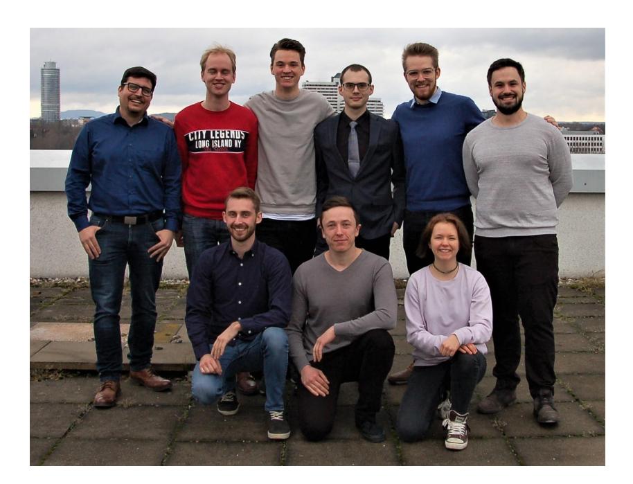
The new team consists of Bachelor and Master students, supervised by a former teammember and Master of Applied Research student. In addition, former teammembers will be involved in the training process of the new teammembers during 2019.
As mentioned earlier, the new team also has to use a new mobile platform, as the old system is not reliable anymore and therefore not usable in a competition. During this process, they will also modify the current software so it can be used on the new system. Although the old system was very successful, the new team members will add new features and improvements during the transition process regarding both hard- and software. This includes the gripper, task planner and object recognition.
3 Hardware Description
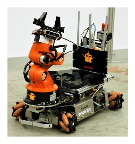
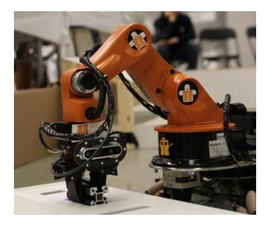
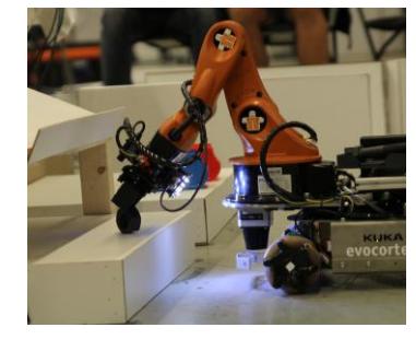
As the new mobile platform is still under construction, we cannot display it yet. Therefore, the old system, which was used in the past competitions, will be discussed here. This should still represent the new system, as the modifications to the standard platform will be maintained. Table 1 shows our current hardware specifications. We use the KUKA omni directional mobile platform youBot (Fig. 2), as it provides a hardware setup almost ready to take part in the competition. Nevertheless, we made some modifications for a better performance.
The platform comes with two PCs with hardware drivers installed, which we replaced by a single Intel NUC i7, because the default processors were outdated and caused performance issues. This main PC is used to control the base and arm of the mobile platform, as well as for image processing and task planning. The KUKA youbot also comes with a Hokuyu 2D-Lidar, which was replaced by two SICK SICK TiM571, one at the front and one at the back of the robot. They are used for mapping, localization, navigation and obstacle avoidance.
The standard endeffector of the Youbot was also replaced by a self developed parallel gripper. The gripper is based on a single Dynamixel servo motor which is attached to a 3D printed rail. Simple mechanics allow an efficient power transmission which enables the motor to grasp with its full torque rather than it being reduced by the lever in the old gripper version. The fin-ray fingers are custom printed out of rubber filament, making them soft and enabling them to close around grasped objects. They are also more wide than standard FESTO fin-ray fingers, so they have an enlarged attack surface and therefore have more tolerance for very small and/or moving objects.
Both sides of the gripper mount are also used to mount the cameras used for perception. The main camera is an Intel RealSense D435 which has been chosen due to its ability to provide a 3D point cloud in short distances. The point of view can be changed with different arm positions, which enables us to use different fields of view for the individual tasks. The secondary perception camera is an endoscope webcam and is used to increase the precision while grasping moving objects. Its field of view points directly towards the gripper and therefore enables better timing of gripper controls.
For an enlarged field of view, an additional Intel RealSense D435 was mounted at the back of the robot. Combined with the front camera and specific arm positions, the barriertape detection can be used while moving both for- and backwards.
The robots inventory consists of three identical 3D printed slots. They are equipped with anti-slip pads, which prevent any movement of the objects, even with heavy robot vibrations. The individual slots are mounted on an adaptable rail system, which enables various mounting positions.
A WLAN-router is mounted the back of the robot to connect the platform and the main PC. It is also used to connect to the refbox or to developer PCs.
Tab. 1: Hardware Specifications.
| PC 1 | |
|---|---|
| CPU | NUC7i7BNH |
| RAM | 16 GB DDR4 |
| OS | Ubuntu 16.04 |
| Gripper | |
| Type | 3D printed, parallel rail |
| Motor | Dynamixel AX-12A |
| Sensors | |
| Lidar Front | SICK TiM571 |
| Lidar Back | SICK TiM571 |
| 3D-cam arm | Intel RealSense D435 |
| 2D-cam gripper | Endoscope Cam |
| 3D-cam back | Intel RealSense D435 |
4 Software Description
We use different open source software packages to compete in the contests. Image processing is handled with OpenCV library (2D image processing and object recognition) and PCL (3D image processing). For mapping and navigation we use gmapping and navigation-stack ROS-packages. Additionally robot-pose-ekf package is used for fusing the data from the IMU and the wheel encoders, to provide more accurate data to the navigation and localization system.
The main software packages are based on ROS and explained in the following sections. These include the state machine (chapter 4.1), global and local localization (chapter 4.2) and packages for perception (chapter 4.3) and manipulation (chapter 4.4). We also improved the rotating table approach (chapter 4.5).
To perform the transportation logistics, a task planner node processes the orders received from the referee box and calculates the best route considering the maximum transport capacity and distances between the workstations. This module finds the optimal solution for up to seven objects. For more objects, the algorithm is simplified to reduce computation time, while generating only slightly worse orders.
4.1 State Machine
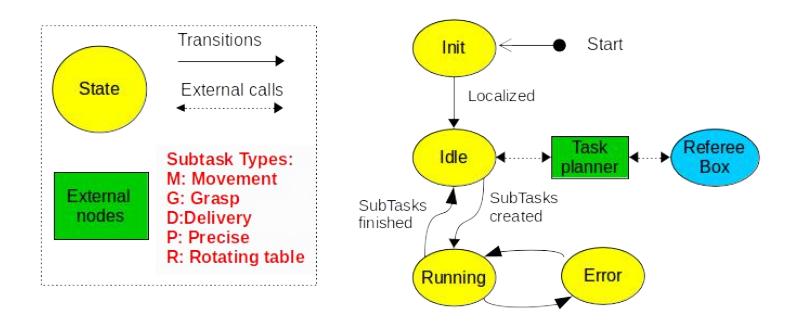
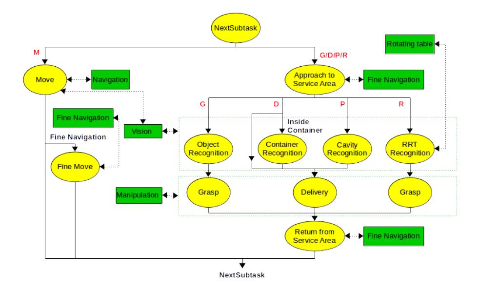
The main control of the robot is coordinated over the state machine in Fig. 2. It starts with an initialization state where the robot receives the map and tries to localize itself on it. From there, it moves to the "stateIdle" and waits for new tasks to perform. The Referee Box provides the orders which are processed by the task planner node and sent to the state machine divided into a vector of smaller subtasks. The subtasks Move, Grasp, Delivery, PreciseDelivery and RotatingTable are now managed in the "stateRunning". Once every subtask is finished it returns to the "stateIdle" to wait again for new tasks to perform.
The first subtask is usually a Move action performed over the navigation node. Depending on the required accuracy on the localization, the robot may execute a fine navigation approach. Both modules are explained in section 4.2. After an specific workstation location is reached, the robot may look for a specific object, container or cavity on the workstation. In case of a Grasp subtask, the exact pose of the desired object is identified. For Delivering an object, the robot must recognize the exact pose of containers or cavities for PreciseDelivery. Once the desired pose is located, the arm manipulation is activated, whether for picking up and storing the object on the robot or for delivering it. The perception and manipulation nodes are explained in sections 4.3 and 4.4 respectively. In case of a RotatingTable subtask, before grasping an object, a preprocessing step to determine objects velocity and pose in the table is required (section 4.5). Once the manipulation subtask is finished, the robot moves away from the service area and returns to the "stateNextSubtask" that will manage the following subtask to do.
In addition, most of the states have error handling behaviors that manage recovery actions such as in case a navigation goal is not reachable, an object cannot be found or a grasping was unsuccessful. It is important to notice these failures and react to them by repeating the action or triggering planning modifications. The state machine framework can be found on GitHub under our laboratory's repository.
4.2 Navigation and Localization
For localization in the arena, we use our own particle filter algorithm. Its functionality is close to amcl localization, as described in [1] and [4]. The algorithm is capable of using two laser scanners and an omnidirectional movement model. Due to the Monte Carlo filtering approach, our localization is robust and accurate enough to provide useful positioning data to the navigation system. Positioning error with our particle filter is about 6 cm, depending on the complexity and speed of the actual movement.
For more accurate positioning, such as approximation to service areas and moving left and right to find the objects on them, we use an approach based on the front laser scanner data. Initially, the robot is positioned by means of the particle filter localization and ROS navigation. If the service area is not visible in the laser scan due to its small height, the robot is moved to the destination pose using particle filter localization and two separate controllers for x and y movement. If the service area is high enough, RANSAC algorithm [2] is used to detect the workstation in the laser scan. Out of this, the distance and angle relative to the area are computed. Using this information, the robot moves in a constant distance along the workstation. We achieved a mean positioning error of under 3 cm during a navigation benchmark tests performed in the European Robotics League local tournament in Milan.
4.3 Perception
This section introduces the implemented nodes for the different perception tasks. The object detection is presented first. Subsequent the detection of the barrier tape is described. Finally the box detection is depicted.
Object Detection
To grasp objects reliably, a stable object recognition is required. For this purpose, an Intel RealSense D435 RGB-D camera is used.
Firstly, the robot navigates to a pregrasp position. Once the base reaches this position, the arm is positioned above the service area. Due to the limited field of view, the robot base moves first left, then right so all the objects in the workstation can be discovered.
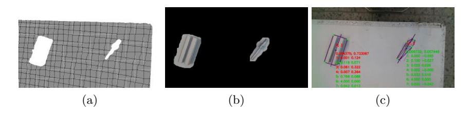
On each position, the plane of the service area is searched in the point cloud using the RANSAC [2] algorithm. Afterwards the detected points are projected to the 2D-RGB image and used as a mask to segment the objects in the 2D-image (Fig.4 a and b).
As all workstations have a white surface, the canny edge detector is used in order to find the concave border of the object in the segmented images for a more accurate result. To classify an object, the following features are extracted: length, width, area, circle factor, corners count, height and black area. The distance to the workstation surface and the camera calibration matrix is used to calculate distance invariant values. With the help of a kNN classifier and the extracted features, the similarity to each previously trained item is calculated. With this information and the inventory information from the referee box, the best possible fitting combination for the detected object on the workstation is searched. To estimate the location of the object, its mass center is calculated. For the rotation of the object, the main axis of inertia is computed and used. The robot will now move in front of the elected object and activate the object recognition again to obtain a more accurate gripping pose. For the newly introduced challenge of unknown orientation of the objects, the objects are trained from all possible orientations. The corresponding height of the detected object will be passed to the manipulation node for correct grasping. The use of the same features of the corresponding objects is an advantage of this approach. The features of black area and height are not considered, as they are not needed for a successful classification.
Barrier Tape Detection
Yellow/black barrier tapes are used to mark restricted areas in the RoboCup@Work competition. If the robot crosses this tape the team is penalized with point deduction.
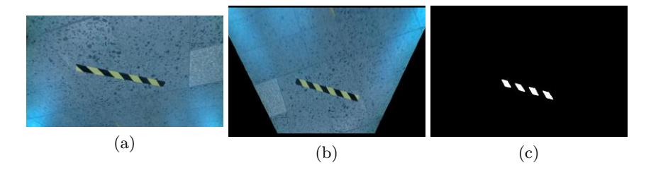
In order to detect this barrier tape the camera image is transformed in bird'seye perspective. Next the image is filtered by RGB and HSV values, which correspond with the yellow part of the barrier tape. For the next step the HU-Moments are calculated and compared to filter out false shapes. Afterwards the detected shapes are transformed and saved in a global map. This gives the robot the ability to avoid the barrier tape even it is not visible in the camera image anymore.
Box Detection
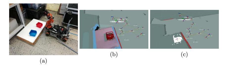
Some of the tasks require an object placement into a blue or a red box (see Fig. 6a). The boxes are easily distinguishable from the background because of their color. Therefore a different strategy is used instead of the described object detection in section 4.3. The advantage is a faster detection of the drop point. In front of the workstation the robot arm is moved in order to position the camera in a 45° angle to the workstation. Subsequently the point cloud is filtered by the color of the searched box (Fig. 6c). If the filtered point cloud is too small, the robot drives closer to the workstation. If no colored points could be detected, the robot will move to the left side first, then to the right side, until a significant amount of points is found. After that the mass center of the filtered point cloud is calculated and passed to the manipulation node as the drop point for the object.
4.4 Manipulation
The manipulation controller is responsible for arm and gripper controls, as well as for inventory management. It provides interfaces for arm positions, grasping or placing tasks and for linear arm movements.
At the beginning of a grasp or placement process, it receives the target pose from the perception node. A self developed algorithm for the inverse kinematics and interpolation plans a linear and orthogonal trajectory to the workstation, object or container. This prevents the gripper from accidentally touching or moving other objects lying on the workstation. Safety behaviors have been implemented during the grasping and placing process to ensure a reliable object handling and inventory management. In specific cases where objects are lost, the affected inventory slot is blocked to further use. The inventory state is broadcasted, so it can be used e.g. by the task planner.
For 2018, the placement process for the shelf workstations was adapted to the changes in the rulebook. Placing an object below the shelf is higher rewarded than placing it on top, because its more likely to cause a collision with parts of the sensor head attached to the gripper. Therefore, a custom placement trajectory has been added to ensure safe operation in the enclosed space below the shelf. Additionally, the grasping process for moved objects was modified to enable more accurate timing and placement of the TCP. Both improvements contributed to increase scores in the competition.
The gripper controller consists of two separated nodes. The driver node runs a microcontroller program which is connected to the Dynamixel servo motors. It initializes and controls the motors position, torque and speed. The microcontroller is connected to the main PC via USB and offers an interface for motor controls and parameter settings. The gripper controller node runs on the main PC and offers dynamic reconfigure options and the grasping services used by the manipulation controller and other nodes. It uses the current torque applied to the motor to determine if an object has been grasped. The torque feedback is also used to prevent the motor from overcurrents by reducing the torque in case of high loads.
4.5 Rotating Turntable
The following algorithm considers various parameters such as the rotation speed, rotating direction and the pose of each object on the table to determine grasping position and timing.
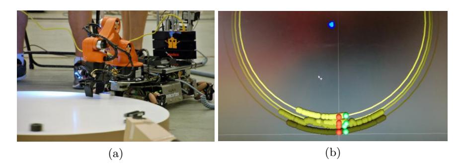
The robot first navigates to the rotating turntable and extends the manipulator arm to an object detection position. Only performed once, an object recognition preprocessing approach is started to obtain the rotating table speed and the direction of rotation. First, the 2D position, the time stamp and the type of incoming objects into the camera visual field are recorded over a defined time. Second, the gathered data is used to determine objects circular paths, defining specific grasping position for each circular path. Figure 9b shows a result of this process determining four circular paths with four different grasping positions (red marked).
With the collected data points of each circular path, a RANSAC-based algorithm [2] calculates the rotation speed of the table, its center (blue marked in Fig. 9b) and the radius of each determined path. Having all necessary information and making use of the previously recorded time stamps, it is possible to estimate an approximate moment, when each object passes the object grasping position. To achieve an accurate grasping, an additional stereoscope RGB camera has been attached on top of the manipulator. A background change algorithm is now applied to the image in order to detect the object entrance in the camera view. The previously calculated circular path velocity is used to close the gripper at the right moment.
Using the implemented feedback of the gripper, the robot recognizes whether grasping was successful or has failed. In case of success, the object is placed on the robot and the manipulator then moves over the next circular path to grasp the remaining objects. If the grasping fails, the manipulator stays in the position and waits one more time until the same object arrives at the RGB camera. If this retry fails again, the robot tries to grasp the next object on the rotating turntable.
5 Conclusion and Future Work
This paper described the participation of team AutonOHM in the RoboCup- @work league. It contains detailed information of the current hardware setup and software packages like navigation, perception and manipulation.
To enable the new team to participate this year and defend the @work champions title, we are building a new mobile platform. In this transition process, the gripper mechanism will be optimized to ensure reliable torque detection. Also our battery and power supply will be improved to meet longer runtimes needed for the finals or long-term tests.
The software will be refactored, so it can be used on the new system. During this process, the object detection will be enhanced by a neuronal network for more stable classification of the objects. In addition, the barriertape detection will be slightly adapted to be more versatile regarding camera angle and lighting.
References
- F Dellaert, D Fox, W Burgard, and S Thrun. Monte Carlo localization for mobile robots. Proceedings 1999 IEEE International Conference on Robotics and Automation (Cat. No.99CH36288C), 2(May):1322–1328, 1999.
- Martin A Fischler and Robert C Bolles. Random Sample Consensus: A Paradigm for Model Fitting with Applications to Image Analysis and Automated Cartography. Commun. ACM, 24(6):381–395, 1981.
- Gerhard K. Kraetzschmar, Nico Hochgeschwender, Walter Nowak, Frederik Hegger, Sven Schneider, Rhama Dwiputra, Jakob Berghofer, and Rainer Bischoff. RoboCup@Work: Competing for the Factory of the Future. pages 171–182. Springer, Cham, 2015.
- S Thrun, W Burgard, and D Fox. Probablistic Robotics. Massachusetts Institute of Technology, 2006.