b-it-bots RoboCup@Work Team Description Paper
Naresh Kumar Gurulingan, Ramesh Kumar, Shweta Mahajan, Abhishek Padalkar, Djordje Vukcevic, Mohammad Wasil, Santosh Thoduka, Deebul Nair, Ahmed Abdelrahman, Sushant Chavan, Iman Awaad, Sven Schneider, Paul G. Plöger, Gerhard K. Kraetzschmar
Bonn-Rhein-Sieg University of Applied Sciences Department of Computer Science Grantham-Allee 20, 53757 Sankt Augustin, Germany
Abstract This paper presents the b-it-bots RoboCup@Work team and its current hardware and functional architecture for the KUKA youBot robot. We describe the underlying software framework and the developed capabilities required for operating in industrial environments including features such as reliable and precise navigation, flexible manipulation, robust object recognition and task planning.
Introduction
The b-it-bots RoboCup@Work team at the Bonn-Rhein-Sieg University of Applied Sciences (BRSU) was established in the beginning of 2012. Participation in various international competitions has resulted in several podium positions, including runner-up at the world championship RoboCup 2018 in Montreal. The team consists of Master of Science in Autonomous Systems students, who are advised by two professors. The results of several research and development (R&D) as well as Master's thesis projects have been integrated into a highly-functional robot control software system. Our main research interests include mobile manipulation in industrial settings, omni-directional navigation in unconstrained environments, environment modeling and robot perception in general.
Robot Platform
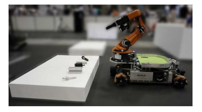
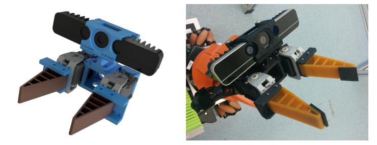
The KUKA youBot [3] is the applied robot platform of our RoboCup@Work team (see Figure 1). It is equipped with a 5-DoF manipulator, a two finger gripper and an omni-directional platform. In the front and the back of the platform, two Hokuyo URG-04LX laser range finders are mounted to support robust localization, navigation and precise placement of the omni-directional base. Each laser scanner is configured with an opening angle of 190◦ to reduce the blind spot area to the left and right of the robot. For perception-related tasks, a closerange RGB-D camera is mounted on the manipulator to the gripper palm. The Intel® RealSense™ D435 camera [2] supports a range from approximately 0.11 m up to 10 m and operates on 30 Hz for the RGB- and on 90 Hz for the depth stream. We also use the Asus Xtion Pro for certain tasks. This sensor information is used for general perception tasks, such as: 3D scene segmentation, object detection and recognition and barrier tape detection. The standard internal computer of the youBot has been replaced by one which has an Intel® Core i5 processor in order to perform the perception tasks; which are computationally intensive. Another custom modification has been made for the youBot gripper (based on the design of [4]) which enhances the opening range to 6.5 cm and enables grasping of a wider range of objects. The new gripper (see Figure 2) is actuated with two Dynamixel AX-12A servo motors which provide a position interface and force-feedback information. This information can be used to perform grasp verification. A final modification was performed on the back platform of the youBot. It has been replaced with a new light-weight aluminum version, the position of which can be manually adjusted forward and backward. This allows to adapt the position of the plate for different tasks and objects easily.
All technical drawings to the previously described modifications, as well as various 3D printed sensor mounts, e.g. for the laser scanner and the RGB-D camera, have been made public [6].
Robot Software Framework
The underlying software framework is based on ROS, the Robot Operating System [13]. We use the ROS communication infrastructure to pass information as messages on topics between the functional components. Compared to services and actions, topics support non-blocking communication and the possibility of listening (e.g. by monitoring nodes) to the communication between two or more nodes at any time. The wide range of various tools provided by ROS are utilized for visualization, testing and debugging the whole system. In our development process, we focus on designing small, light-weight and modular components, which can be reused in various processing pipelines, e.g. in pipelines of different domains or even on a different robot platform, like the Care-O-bot 3 [14]. We have also standardized our nodes with the addition of event in and event out topics. Our components listen to the event in topic which expects simple command messages and allow for: starting, stopping or triggering (run once) of nodes. The components provide feedback of their status on the event out topic when they finish. This allows us to coordinate and control the components with either simpler state machines or task planning; in either case, the control flow and data flow between the components remains separated. This also allows us turn off computationally expensive nodes when they are not needed.
In 2016, the team published a snapshot of their repository [5] used for the KUKA youBot and the @Work league.
Navigation
Several components have been developed and integrated to move the robot from one place to another in cluttered and even narrow environments.
Map-based Navigation
The navigation components we use are based on the ROS navigation stack move_base which uses an occupancy map together with a global and local path planner. For the local path planner a Dynamic-Window-Approach (DWA) is deployed which plans and executes omni-directional movements for the robot's base. This enhances the maneuverability, especially in narrow environments.
The vast amount of configuration parameters of the move_base component have been fine-tuned through experiments with several and differently structured environments in simulation (e.g. a corridor, narrow passages, maze, etc.). Our robot is able to navigate with a maximum linear velocity of 1.0 m/s and a maximum angular velocity of 1.5 rad/s. The lateral speed is kept low due the relatively large blind spots to the left and right of the robot. With these velocities the robot is still able to react fast enough to avoid, decelerate or brake, when there are objects moving dynamically in the environment.
Currently we are working on further improvements for the move_base component, namely local and global planner, to allow more omni-directional motions, especially at the beginning and end of a global path.
Force-Field Recovery Behavior
In certain situations, especially in narrow passages, the robot can get stuck; for example, due to an overshoot the robots circumscribed radius is now in an area of the costmap which is annotated as an obstacle. The ROS navigation stack does not yet provide a proper behavior to recover from such kind of situation. We extended the implementation by smARTLab@work [9] of the force-field recovery behavior [11] which moves the robot away from obstacles in its vicinity. First, a subsection of the local costmap with lethal cost in a certain radius is taken into account. Each obstacle in the subsection is considered as a vector applying a repulsive force on the center of the robot. By summing up all force vectors to one overall force, we obtain the best possible direction in which the robot should move to no longer be stuck. The resultant force is multiplied with a velocity scale factor and sent as linear and angular velocities to the base controller. This has proved to be very helpful for our navigation and has freed the robot in many situations. The behavior is implemented as a plugin for the ROS navigation stack and has been tested on several other robots such as the Care-O-bot 3.
Perception
Several components have been developed for processing the image and point cloud data from the arm-mounted camera.
Object Recognition
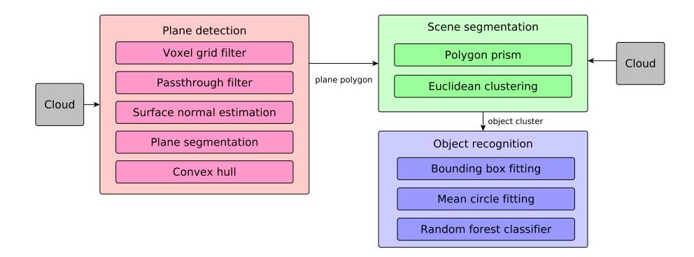
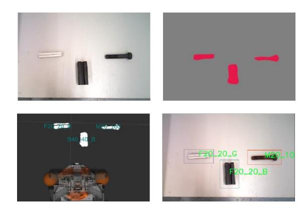
Perception of objects relevant for industrial environments is particularly challenging. The objects are typically small and often made of reflective materials such as metal. We use a RGB-D camera which provides both intensity and depth images of the environment. This enables effective scene segmentation and object clustering. But the spatial resolution is low even at the close range, and a significant degree of flickering corrupts the depth images. Thus, for the object detection and recognition task we use both 3D and 2D methods. The 3D perception pipeline is outlined in figure 3.
We capture a single point cloud and downsample it using a voxel grid filter in order to reduce the computational complexity. We then apply passthrough filters to restrict the FOV which removes irrelevant data and further reduces the computational burden. In order to perform plane segmentation, we first calculate the surface normals of the cloud and use a sample consensus method to segment a single horizontal plane. The convex hull of the segmented plane is computed and represented as a planar polygon. The prism of points above the polygon are segmented and clustered to individual object pointclouds.
For object recognition, we fit a minimal bounding box to each cluster and find the mean circle fit perpendicular to the third principal axis of the cluster. Additionally, mean circles are fit on slices made along the first principal axis [16]. The dimensions of the bounding box, radius, fitting error of mean circles, and the average color of all points serve as feature vector for the previously trained random forest classifier. Based on this information, it outputs the predicted object type along with the probability of correct classification.
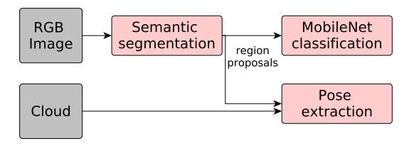
In addition to 3D-based object recognition, we also use RGB-based object recognition. The pipeline consists of two parts as depicted in figure 4: semantic segmentation and object recognition. Semantic segmentation is a pixel-wise classification problem with the goal of assigning a class from a list of desired classes to every pixel in an image. The resultant image splits objects of interest into different regions thereby achieving the intended segmentation into meaningful regions. We use DeepLabv3+ models with resource efficient network backbone such as Xception [10] and MobileNetv2 [12], which outputs object boundaries and produces a single channel segmentation map as shown in figure 5, classifying the pixels into object or background. We use the object boundary proposals as the inputs for the RGB object recognition network using the baseline MobileNet V1 to classify the objects [12]. It is an architecture designed to work on mobile devices with a limited computational power. This is achieved with the use of depthwise separable convolutions which separates into different layers. A single filter is applied to each of the inputs (depthwise convolution) and the results are combined using 1x1 convolutions (pointwise convolutions) resulting in fewer computations and smaller model size. We also use the Intel Movidius Neural Compute Stick (NCS) for additional computational power at inference time [1].
We finally combine the classification results from 3D and RGB object recognition selecting the label based on different criteria such as the probabilities output by the classifiers.
Cavity Recognition
For certain tasks, the robot is required to insert objects into cavities (e.g. in a peg-in-hole task). The correct cavity has to be chosen and the respective object needs to be precisely placed into it.
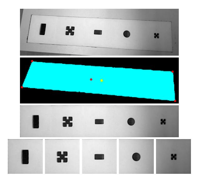
For a given image, initially, contours of each cavity are extracted based on limits on the area of detected contours. Based on the centroids of the contours, the input image is cropped. We apply Harris corner detection to extract the four points of the outer border of the tiles and apply a homography to transform the perspective of the image. Each individual cavity is cropped and matched with templates stored in the database using simple image comparison methods such as Structurality Similarity Index Measure (SSIM) and Mean Square Error (MSE). The intermediate outputs of the process is shown in figure 6.
Object Manipulation
In order to grasp objects reliably, several components have been developed and integrated on the robot.
From the object recognition, the pose of the object to be grasped is retrieved. This pose is the input to a pre-grasp planner component which computes a pregrasp configuration based on the type of grasp, a distance offset and constraints imposed by the robot's manipulator and end effector. Due to its kinematic constraints, the robot might not be able to reach this computed pre-grasp configuration with its end effector. Thus, a set of poses is sampled around the object's pose. An inverse kinematics solver is then used to find one reachable pre-grasp pose from the list of sampled poses.
The rationale behind this process is to move the robot's end effector close to the target object instead of directly onto the object. This ensures that the end effector will not collide with the surface the object is located on. In a final step, the object is approached with the end effector through a linear motion in the Cartesian space.
Once the end effector reached the grasp pose, the gripper of the robot is closed. A grasp monitor checks whether the object is grasped successfully utilizing the force and position feedback of the two Dynamixel motors, as well as a photo reflective sensor mounted on the gripper tips.
Task Planning
Many robot application, especially in competitions, have been developed using finite-state machines (FSM). But even for apparently simple tasks, such a FSM can be very complex and thus become easily confusing for humans. Therefore, our current FSMs have been replaced with a task planner.
At the moment, the Mercury 2014 planner is used for task planning. However, the plans generated by this planner were found to be sub-optimal given the planning time constraints, in addition to containing redundant actions. Therefore, the LAMA planner [15] was chosen as an alternative, following a comparative study [7] conducted to evaluate similar planners that were submitted for the International Planning Competition 2018. The LAMA planner generated nearoptimal plans, containing no redundancies, and thus clearly outperformed the Mercury planner.
The LAMA planner is built on the Fast Downward planning system and uses PDDL. As such, it uses similar interfaces to those of the Mercury planner. The planner allows specifying various cost information. In terms of RoboCup@Work, these costs and can be, for example, distances between locations or probabilities of how good a particular object can be perceived or grasped.
In order to integrate the new planner into our current architecture, the existing FSMs have been refactored to very small and clear state machines covering only basic actions, like move-to-location, perceive-object, grasp-object or place-object. For a particular task, the planner then generates a sequence of those actions in order to achieve the overall goal. Finally, this plan is being executed and monitored. In case of a failure during one of the actions, replanning is being triggered and a new plan is generated based on the current information available in the knowledge base.
By utilizing a task planner instead of FSMs, the maintenance has become easier due to the fact that only small state machines need to be modified or tested. Further, the previous FSMs designer does not need to consider and construct all possible error cases by hand.
Conclusion
In this paper we presented several modifications applied to the standard youBot hardware configuration as well as the functional core components of our current software architecture. Besides the development of new functionality, we also focus on developing components in such a manner that they are robot independent and can be reused for a wide range of other robots with even a different hardware configuration. We applied the component-oriented development approach defined in BRICS [8] for creating our software which resulted in high feasibility when several heterogeneous components are composed into a complete system.
Acknowledgement
We gratefully acknowledge the continued support of the team by the b-it Bonn-Aachen International Center for Information Technology, Bonn-Rhein-Sieg University of Applied Sciences and AStA H-BRS. Finally, we also acknowledge the support by our sponsors MathWorks, SolidWorks and igus GmbH.
References
- Intel Neural Compute Stick. https://software.intel.com/en-us/movidius-ncs. (Online: 12.02.2019.).
- Intel RealSense D435 camera. https://realsense.intel.com/depth-camera/#D415_D435. (Online: 04.02.2019.).
- KUKA youBot. http://www.youbot-store.com. (Online: 23.03.2017.).
- LUHbots RoboCup@Work team. http://www.luhbots.de. (Online: 23.03.2017.).
- Software repository of b-it-bots team used at RoboCup 2016 in Germany. https://github.com/mas-group/robocup-at-work. (Online: 23.03.2017.).
- Technical drawings of BRSU youBot modifications. https://github.com/mas-group/technical_drawings. (Online: 23.03.2017.).
- Ahmed Abdelrahman, Sushant Chavan, and Nga Tran. Evaluation of new planners. Unpublished manuscript. Hochschule Bonn Rhein Sieg, 2019.
- R. Bischoff, T. Guhl, E. Prassler, W. Nowak, G. Kraetzschmar, H. Bruyninckx, P. Soetens, M. Haegele, A. Pott, P. Breedveld, J. Broenink, D. Brugali, and N. Tomatis. Brics - best practice in robotics. In In Proceedings of the IFR International Symposium on Robotics (ISR 2010), Munich, Germany., June 2010.
- Broecker, Bastian and Burger, Benjamin and Claes, Daniel and Fossel, Joscha and Schnieders, Benjamin and Williams, Richard and Tuyls, Karl. The smART-Lab@Work 2016 Team Description Paper. In RoboCup, Leipzig, Germany, 2016.
- Liang-Chieh Chen, Yukun Zhu, George Papandreou, Florian Schroff, and Hartwig Adam. Encoder-decoder with atrous separable convolution for semantic image segmentation. arXiv preprint arXiv:1802.02611, 2018.
- Chong, Nak Young and Kotoku, Tetsuo and Ohba, Kohtaro and Tanie, Kazuo. Virtual repulsive force field guided coordination for multi-telerobot collaboration. In Robotics and Automation, 2001. Proceedings 2001 ICRA. IEEE International Conference on, volume 1, pages 1013–1018. IEEE, 2001.
- Andrew G Howard, Menglong Zhu, Bo Chen, Dmitry Kalenichenko, Weijun Wang, Tobias Weyand, Marco Andreetto, and Hartwig Adam. Mobilenets: Efficient convolutional neural networks for mobile vision applications. arXiv preprint arXiv:1704.04861, 2017.
- Morgan Quigley, Ken Conley, Brian P. Gerkey, Josh Faust, Tully Foote, Jeremy Leibs, Rob Wheeler, and Andrew Y. Ng. Ros: an open-source robot operating system. In ICRA Workshop on Open Source Software, 2009.
- U. Reiser, C. Connette, J. Fischer, J. Kubacki, A. Bubeck, F. Weisshardt, T. Jacobs, C. Parlitz, M. Hagele, and A. Verl. Care-o-bot 3 - creating a product vision for service robot applications by integrating design and technology. In IEEE/RSJ International Conference on Intelligent Robots and Systems (IROS), pages 1992–1998, Oct 2009.
- Silvia Richter, Matthias Westphal, and Malte Helmert. Lama 2008 and 2011. In International Planning Competition, pages 117–124, 2011.
- Thoduka, Santosh and Pazekha, Stepan and Moriarty, Alexander and Kraetzschmar, Gerhard K. RGB-D-Based Features for Recognition of Textureless Objects. In Proceedings of the 20th RoboCup International Symposium, Leipzig, Germany, 2016.