AutonOhm
Marco Masannek, Sally Zeitler
University of Applied Sciences Nuremberg Georg-Simon-Ohm
Abstract This team description paper presents the team AutonOHM and their solutions to the challenges of the RoboCup@Work league. The hardware section covers the robot setup, which was developed using knowledge gained from the outdated KUKA youbot platform. Custom solution approaches for the @Work navigation, perception and manipulation tasks are discussed in the software section, as well as a control architecture for the autonomous task completion. Furthermore, improvements for future participation in the RoboCups 2022 are discussed.
1 Introduction
The RoboCup@Work league, established in 2012, focuses on the use of mobile manipulators and their integration with automation equipment for performing industrial-relevant tasks [1]. The 2019 rulebook [2] introduced new challenges for the teams, including visual obstacle detection in most competitions and the use of arbitrary surfaces in some of the basic transportation tasks.
These changes made a re-development of our vision approach necessary, which now consists of two neural networks. As the dataset generation plays a major role in the training of such, we developed an automated dataset generation using Blender (see chapter 4). The extended use of barriertape to block certain areas of the arena increased the planning inaccuracy of our old task planner, which is why we re-implemented the control architecture to enable replanning during task execution. The change of major parts of the software also required a refactoring of the overall system, as of which a custom software architecture approach was developed, which may be used and applied for most autonomous mobile robots and shall help keeping track of used programs as well as leaving room for extensions.
The supply issue with the old KUKA youbot also brought up the requirement for a new robot, which we developed over the course of the last two years. Our major hardware improvements such as the elimination of the blind spots at the robot's sides and other features are discussed in chapter 3. The conclusion in chapter 5 gives a summary of the developments during the last season as well as an outlook to our current work, such as the use of new neural network architectures for object detection, reworking of our gripper concept and implementation of performance monitoring.
2 AutonOHM
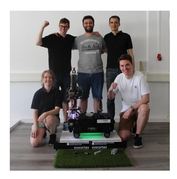
The AutonOHM-@Work team at the University of Applied Sciences Nuremberg Georg-Simon-Ohm was founded in September 2014. In 2017, the team was able to win both the German (Magdeburg) and also the World Championship (Nagoya) title. With the knowledge and experience gained in the former tournaments, the team was also able to defend both of these titles in 2018.
In late 2018 most of the members finished their studies, which is why the team had to be rebuilt in 2019. Since then, the team consists of a small group of "core" members and changing short-term members, which were mostly active in 2020.
In 2021 the AutonOHM-@Work team won the SciRoc Challenge 2021 - Episode 5: Shopping Pick & Pack, as well as the World Championship title in the RoboCup Worldwide competition. Since late 2021 the team has welcomed new members.
Due to the discontinuation of the KUKA youbot, the team started collaborating with the company Evocortex GmbH [3] in 2019. They are producing customizable robot platforms which are equipped with mecanum drives and designed for research projects. The partnership contains the supply with a robot for the team in exchange for sharing and alpha-testing the platform. As the @Work scenario is designed to be industry related, giving feedback and feature suggestions, as well as the bidirectional knowledge exchange is helping both sides to constantly improve.
3 Hardware Description
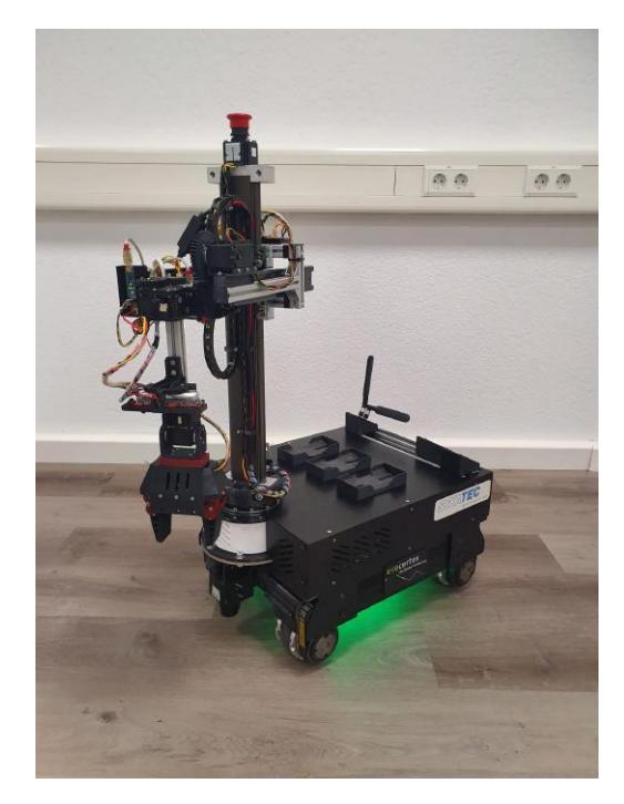
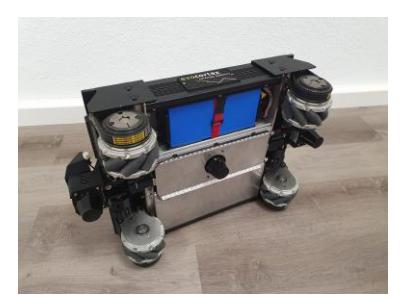
We are using a customized Evocortex R&D platform with the smallest formfactor available. The platform is equipped with an omnidirectional mecanum drive, an aluminum chassis capable of carrying loads up to 100 kg and a Li-Ion Battery with a nominal voltage of 24V and roughly 12.5Ah capacity. In our configuration, the platform does not come any sensors, power management or computation units, which means it only serves as our base. Every further component needed, like the manipulator or the pc, was mounted in or on the chassis.
3.1 Sensors
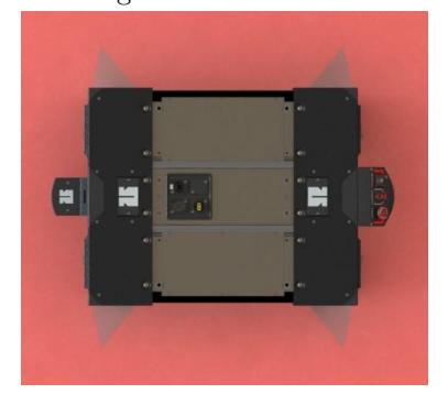
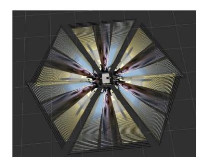
Lidars Mapping, navigation and the detection of physical obstacles is performed by three SICK TiM571 2D lidars. One each is mounted at the front and the back of the robot scanning 180◦ . As this creates deadzones at the robot's sides, a third sensor was mounted centered at the bottom of the robot. It utilizes the design of the new platform by scanning 90◦ to each side and therefore eliminates the leftover dead zones, resulting in a full 360◦ scan of the robot's surroundings.
Cameras We use an Intel RealSense D435 3D-camera for the object perception. It is attached to the manipulator in such a way that it can be positioned above the workstations so that we can detect the surface and the position of the objects.
For barriertape detection, multiple ELP USB fisheye cameras can be mounted around the robot, which enables a 360° view. During the competition, we usually rely on a single fisheye camera because we have observed that all of the barrier tape is still detected.
3.2 PC
The newly introduced neural networks require a GPU to be available for computation onboard of the robot. As embedded GPU chips such as the Nvidia Jetson TX2 do not provide enough processing power for the task optimization and navigation algorithms, we designed a custom PC solution constisting of a powerful AMD Ryzen 3700x processor, a mini-ATX mainboard and a low power Nvidia GTX1650 graphics card, which is connected to the mainboard with a riser cable. This enabled us to build a flat case with both the mainboard and the graphics card safely mounted inside, right next to each other. The form factor of the case makes it possible to slide it into the robot's back, similar to a server rack.
3.3 PSU
We developed a custom psu circuit board containing emergency switches for the actuators, a main power switch and high efficiency voltage controllers for 5V and 12V. It is equipped with a custom designed plug system with selectable voltage, so every peripheral device can be connected using the same plug type. In addition to that, we use an adjustable DC-DC controller for the power supply of the manipulator, as its power consumption exceeds the limits of the onboard controllers. For the custom PC system, we use a standard 250W automotive ATX power supply.
3.4 Manipulator
Arm The EvoRobot does not include a manipulator, which is why an additional manipulator has to be chosen and mounted. As our budget did not allow the purchase of an applicable robot arm, we had to develop a custom solution.
The designed arm must be able to perform pick and place operations for objects with a maximum weight of 250g to fulfill tasks in the @work league. Its maximum payload should be at least 600g, as the gripper and camera also add up to about 300g. Industrial pick and place applications are often solved with SCARA robot arms. However, the SCARA concept was not exactly suitable for our purpose, which is why we combined the idea of a cylindrical robot arm with joint arms.
The concept utilizes linear gears to control the z- and x-axis of the arm. In combination with the first rotational z joint, the TCP can be moved to every point (x, y, z) given within the operation area. For more flexibility, two additional rotational joints (y and z) were added between the TCP and the linear x-axis to compensate for the object and arm orientation. The actuators we used are simple Dynamixel MX-106 and AX-64 motors, which were available in our laboratory. They have enough power to control each axis, with the linear z axis being able to lift up to 5 kg.
Most of the parts used were 3D printed using PETG material, including some of the main mounting parts and all gears. The main bearing, the linear rail and the full extension tray rails have to be purchased. Including the actuators, our current configuration sums up to about 2,500 EUR. We are planning to release the plans once the arm is fully developed, so that any student or research facility can rebuild the arm for educational purposes.
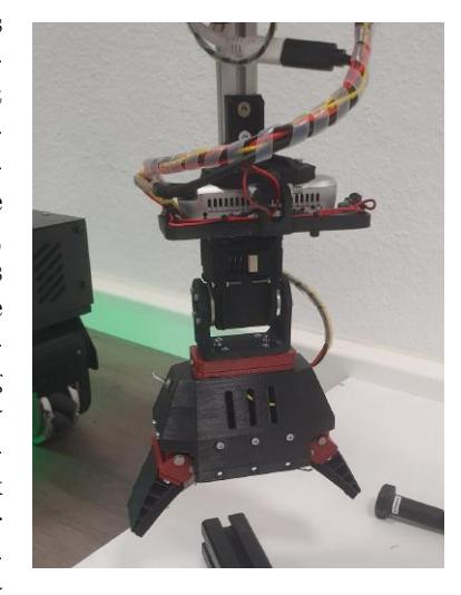
Gripper The gripper concept also utilizes 3D printed linear gears to convert the rotational force of a motor into linear movement of the fingers. It is based on a single Dynamixel AX-12 motor connected to the driving gear. The power transmission enables the motor to grasp objects with its full torque, rather than it being reduced by a lever with its length conditioned by the gripper fingers. The fin-ray fingers are custom printed out of rubber filament, making them soft and enabling them to close around grasped objects. They are also more wide than standard FESTO finray fingers, so they have an enlarged attack surface and therefore have more tolerance for very small and/or moving objects. This gripper concept is currently being revised to allow the use of force feedback.
3.5 Other
Inventory The robot's inventory consists of three identical 3D printed slots. They are equipped with anti-slip pads, which prevent any movement of the objects, even with heavy robot vibrations. The individual slots are mounted on an adaptable rail system, which enables various mounting positions.
Network Setup Our network setup consists of multiple LAN switches onboard of the robot, connecting different mounting layers of the platform. A WLANrouter is used as a DHCP server while also giving wireless remote access to the robot.
RGB Feedback For additional feedback to its viewers, the robot is equipped with two RGB strips at its bottom. They work as a human machine interface and are used to indicate the robot's actions by blinking various color patterns.
4 Software Description
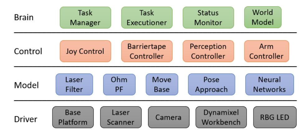
We use Linux Ubuntu 18.04 and ROS Melodic [4] as our operating systems. Over the course of the last seasons, most of the old software has been replaced by newly developed solutions. Therefore, a software architecture proposal was created to simplify the overall structure and to regain system flexibility. Our new design is displayed in fig. 4.
The idea derives from the Model-View-Controller software design pattern, which is adjusted to the usage of the ROS framework. Regarding the frequent use of hardware, an additional driver layer is added below the model layer. Models that need data from hardware, e.g. sensor data, can get them from the individual driver programs. The view layer is realized with each program using interfaces to RVIZ or simple console logging, which makes custom implementations obsolete. Components that require additional control features, such as the robot arm, have dedicated controllers providing simple interfaces for the brain layer, which is responsible for the actual task interpretation and execution. The individual layer components will be explained in the following sections.
4.1 Driver
The driver layer only contains actual hardware control programs, such as the sensor interfaces. The idea here is that the whole layer can be replaced with simulation tools such as Gazebo.
Base Platform The base platform driver converts incoming cmd vel messages into wheel rpm and calculates the odometry from obtained rpm. It stops the robot automatically if the incoming commands time out to prevent uncontrolled movements. An additional twist mux node throttles incoming commands from the joy controller, move base and the pose approach.
Laser Scanner Three sick tim nodes provide the interface to the scanners with given IP adress and scan area configuration. However, as the Lidar is prone to measurement errors such as shadows or reflections, custom laser filters are applied to the raw data for later computation.
Camera We use the Intel Realsense SDK with the provided ROS wrapper. The fisheye cameras are accessed via the ROS usb cam package[20].
Dynamixel Workbench The tower arm is controlled with a controller instance of the dynamixel workbench package. It provides a trajectory interface to control multiple motors at once, which we use for trajectory execution. As our gripper also uses a dynamixel motor, but needs extended access to motor variables (e.g. torque), a dedicated controller instance is used for the gripper controls and feedback.
RGB LED A Teensy Microcontroller runs a control loop for the LED strips. Depending on given brightness, color and mode, the individual LEDs are controlled to enlight, blink or fade.
4.2 Model
Our models contain all algorithms used to challenge the problems the tasks in the @Work league. This includes localization, navigation and perception. The task planner is not included as a model but in the brain layer because it is more convenient to attach it directly to the task manager, as discussed in chapter 4.4.
Laser Filter As mentioned in 4.1, we filter the raw laser data before computing. The first filters are simple area filters to delete the robots wheels from the scan. Otherwise, they would appear as obstacles in the navigation costmap. The second filter is a custom jumping point filter implementation. We faced problems with reflections of the alu profile rails used for the walls of the arena, which caused the robot to mark free space as occupied, even though the points were only single reflections. The filter calculates the x- and y-position for each scan point and checks if there are enough neighbors in close range to mark a point as valid. All points with less than n neighbors in the given range will be handled as measurement errors and therefore deleted.
Ohm PF For localization in the arena, we use our own particle filter algorithm. Its functionality is close to amcl localization, as described in [5] and [13]. The algorithm is capable of using multiple laser scanners and an omnidirectional movement model. Due to the Monte Carlo filtering approach, the localization is robust and accurate enough to provide useful positioning data to the navigation system. Positioning error with the particle filter is about 6 cm, depending on the complexity and speed of the actual movement.
Move Base We use the ROS navigation stack [10] for global path planning and the local path control loops. Path cost calculations are performed by using the costmap 2D plugins. The base layer is a 2D laser map created with gmapping [11, 12]. On top of that, we use a barriertape map layer which contains all detected barriertape points. For local obstacle avoidance, we added an obstacle layer which includes laser data from all three laser scanners. All layers are combined in the final inflation layer. Global pathplanning is computed with the mcr global planner [17] while the path is executed using the TEB local planner [6–9]. As the local planner is not able to precisely navigate to a given goal pose, we set the goal tolerance relatively high. Once we reached our goal with move base, we continue exact positioning with our custom controller, the pose approach.
Pose Approach The pose approach package utilizes a simple PID controller to move the robot to a given pose. It utilizes the robot's localisation pose as input and the target pose as reference. As the controller does not consider costmap obstacles, the maximum distance to the target is 20 cm to prevent collisions. A laser monitor algorithm checks for obstacles in the current scan and stops the robot if necessary.
Fisheye rectification The raw fisheye images need to be rectified to be used as input for the detection network. A specific image pipeline fork [21] is used, which contains this functionality.
NN - Barriertape For the barriertape detection, we use a U-Net with manually labelled datasets. The ROS node receives raw input images and returns a masked binary image with all barriertape pixels marked. We have ported the network node from Python to C++ to increase the detection rate from around 5Hz up to 20Hz.
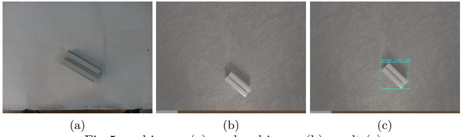
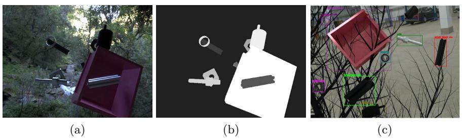
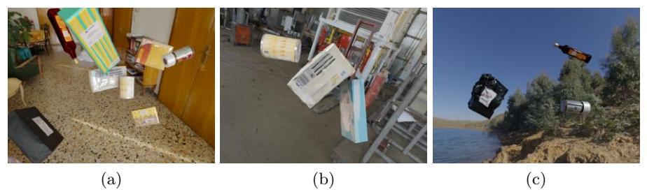
NN - Objects The detection and classification of objects is done with a Tiny-YOLO-v3 network. The node receives a raw input image and returns a vector with the id, bounding box and weight of all objects that were found. As our dataset would require more than 10,000 labelled images, which would require a high amount of time to create, we have implemented an automated dataset creation method using Blender and Python. It basically changes environments, illumination, camera and object pose as well as object appearance in pre-defined bounds. The script created rendered images as well as bounding box, segmentation and 6DoF labels. With this data generation method, data which is quite similar to the original scene (fig. 5) can be created, as well as rather abstract data (fig. 6). We are currently also working on data generation for deformable objects, such as the objects used in the SciRoc Challenge 2021 - Episode 5: Shopping Pick & Pack [19]. Some sample data can be seen in fig. 7
Using an original to artificial image ratio of 1:10, we achieved a detection reliability of over 90% for most scenes. Our data generation scripts are public and free to use [15]. The trained network is converted to TRT-Engine using code from the TRT-YOLO-App from the Deepstream Reference Apps [16]. This increases performance as the CUDA cores will be used more efficient, and makes a detection rate of up to 60Hz possible. In the future, other network types such as segmentation networks and 6DoF networks will be explored.
4.3 Controller
Model nodes that require additional control features are connected to control nodes, which then provide interfaces for the brain layer. They use our robotcustom msgs interfaces to share information about the subtask, workstation or objects. Nodes may have specific subtask types implemented into their behaviour to react optimized.
Joy Control We use a PS3 joystick to move our robot manually (e.g. for mapping). For this, we have implemented a custom teleop joy node with similar functionality.
Barriertape Control The barriertape controller is a custom mapping implementation for visual obstacles. It throttles the input images to the barriertape network and computes the masked images. It is possible to connect multiple cameras to the controller, which will then be iterated in a loop. This enables us to perform 360◦barriertape detection.
Received masked images are converted into a point cloud with a predefined density. This pointcloud is then transformed from the individual camera frame into the global map frame. Afterwards, all new points are compared to the existing map points. New barriertape points that mark cells which are already occupied are ignored to save computation. As we faced problems with image blur and therefore resulting non-precise barriertape detection, we also compute pixels that mark free space (no barriertape detected). They are compared to existing points, which get deleted if they overlap.
The whole map is converted into an occupancy grid and then published periodically, so it can be included in the costmap of the move base node. The node is controlled via service calls, which enable or disable the detection loop. The map is always published once the node finished the init process.
Arm Control As the kinematic model of the tower arm has only one solution for a given TCP position, we developed a custom arm controller node instead of using moveIt. It is possible to adjust the amount and type of joints and links via ROS parameters, only the inverse kinematics solution has to be adjusted for new arms. Using predefined danger zones, the arm executes a self calculated trajectory to the target pose considering the individual motor parameters. The arm is controlled via ROS services or a development GUI for debugging. When using the services, the arm executes a full task using the given information, which means, in case of a pick task, it moves the TCP to the object position, closes the gripper, and stores the object. After the subtask finishes, feedback of the exit status is returned to the caller.
Perception Control The perception control node is responsible for the workstation analysis and object detection. A given scene (3D Pointcloud and RGB image) is analyzed in multiple steps. First, the surface equation of the workstation is calculated using the RANSAC [14] algorithm. If a valid result is obtained, raw images are sent to the object perception network (4.2). All found objects are then localized using the pinhole camera model, the workstation plane and the bounding box pixels. Finally, the position is transformed into the workstation frame and then saved for later usage. For moved objects, multiple positions are recorded and then used to calculate the movement equation with RANSAC.
4.4 Brain
Every node below the brain level needs external controls to fulfil tasks. The brain layer provides nodes which contain the intelligence of the robot, which means the tracking of itself, its environment and the received tasks.
Worldmodel All data obtained about the robot's environment is stored in the worldmodel database. This includes the map, all workstation positions and all detected objects on the workstations. The data can be accessed using service calls.
Status Monitor The status monitor keeps track of the robot itself. It saves the current pose, inventory and state. The associated color code is sent to the RGB LED driver node.
Task Manager The robot can receive tasks from multiple sources, such as the RefBox or voice commands. In order to process different input formats, different parsers are used which standardize the input to a format the task manager can process.
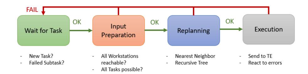
When the robot receives a new transportation task, it must be analyzed and planned before the execution starts. All extracted subtasks are managed by the task manager node, which uses all information available to replan the order of all subtasks. With the increasing numbers of transportation tasks in the competition, high efficiency is crucial to achieve perfect runs.
The score of a single subtask is calculated considering expected duration, points and the risk of failure. These factors may change if certain conditions are met, for example, the navigation time is set to zero if the robot already is at the given position.
Before even starting the planning of subtasks, the received task is analyzed for impossible tasks. This would be the case if the target workstation is unknown or unreachable, or an object is lost. All subtasks that cannot be executed are moved to a deletion vector.
A self developed planning algorithm then calculates the raw score of the remaining subtask vector, followed by a simple nearest neighbor search (NN). This result is then used as input for a recursive tree calculation method, which checks all possible combinations for the subtask and searches for the optimal solution. A branch is only fully calculated if the score sum does not exceed the best solution found with the NN. This way, we have achieved an overall planning time for the BTT3 challenge (14 subtasks) of around 10s. For subtask numbers below 12 the planning only takes 2s. If the task load exceeds 14 tasks, we skip the recursive strategy, as planning time grows exponentially and therefore cannot produce results in the given time frame of a run.
After planning, the replanned subtask vector is iterated and every subtask is sent to the task exectutioner (4.4). If the execution was not successful, the actual task is moved to a failed subtask vector and deleted from the current working STV. The short planning times enable us to replan everytime a subtask fails, or new data is available. This is necessary because even simple changes can cause serious errors in the intentional plan. If certain paths are blocked, the navigation time for transportation tasks can increase dramatically, causing a huge loss of efficiency. A final garbage collection checks all deleted and failed subtasks for plausibility again and adds retrys for possible subtasks.
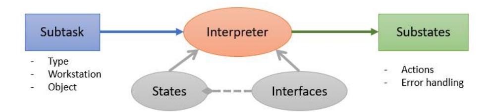
Task Executioner Subtasks that are sent to the Task Executioner get run through an interpreter to extract the actions that are necessary for the task execution. All actions are performed in custom states, which can be adjusted via parameters at creation. The interpreter uses information from the status monitor, the worldmodel and the given subtask to create substates accordingly. The resulting state vector is iterated until its finished or failed. While executing, the node reads and modifies the data in the status monitor and worldmodel package. This way, every change is immediately available for all other nodes too.
5 Conclusion and Future Work
During the last season, we optimized our robot concept and further extended it. Voice recognition was implemented, as well as 360° barriertape detection using fisheye cameras and the foundations for data generation of deformable objects. We successfully participated in the SciRoc Challenge 2021 - Episode 5: Shopping Pick & Pack, where we were able to win the first place. We also managed to regain our world championship title during the 2021 WorldWide RoboCup competition.
In the coming season we plan on further improving our object detection by using other network architectures such as segmentation, 6DoF and grasp detection networks. We are also reworking our gripper concept to enable the use of force feedback, which will further improve our system. Furthermore, we want to introduce performance monitoring, allowing us to identify bottlenecks and plan future improvements. Finally, we are currently working on creating a repository [22], where many aspects of our solution will be publically available. With this repository, we want to share our knowledge to provide other researchers with a basic foundation for autonomous robots and task completion.
We are very much looking forward to the upcoming season, where we aim to defend our title at RoboCup 2022, hopefully in person in Thailand.
References
- RoboCup Atwork Website, https://atwork.robocup.org/. Last accessed 20 Jan 2021
- A. Norouzi, B. Schnieders, S. Zug, J. Martin, D. Nair, C. Steup, G. Kraetzschmar: RoboCup@Work 2019 - Rulebook, https://atwork.robocup.org/rules/, 2019
- EvoCortex Homepage, https://evocortex.org/. Last accessed 20 Jan 2021
- Stanford Artificial Intelligence Laboratory et al., 2018. Robotic Operating System, Available at: https://www.ros.org.
- F. Dellaert, D. Fox, W. Burgard and S. Thrun, "Monte Carlo localization for mobile robots," Proceedings 1999 IEEE International Conference on Robotics and Automation (Cat. No.99CH36288C), Detroit, MI, USA, 1999, pp. 1322-1328 vol.2, doi: 10.1109/ROBOT.1999.772544.
- C. Rösmann, W. Feiten, T. Wösch, F. Hoffmann and T. Bertram: Trajectory modification considering dynamic constraints of autonomous robots. Proc. 7th German Conference on Robotics, Germany, Munich, 2012, pp 74–79.
- C. Rösmann, W. Feiten, T. Wösch, F. Hoffmann and T. Bertram: Efficient trajectory optimization using a sparse model. Proc. IEEE European Conference on Mobile Robots, Spain, Barcelona, 2013, pp. 138–143
- C. Rösmann, F. Hoffmann and T. Bertram: Integrated online trajectory planning and optimization in distinctive topologies, Robotics and Autonomous Systems, Vol. 88, 2017, pp. 142–153
- C. Rösmann, F. Hoffmann and T. Bertram: Planning of Multiple Robot Trajectories in Distinctive Topologies, Proc. IEEE European Conference on Mobile Robots, UK, Lincoln, Sept. 2015
- ROS navigation, http://wiki.ros.org/navigation. Last accessed 20 Jan 2021
- Giorgio Grisetti, Cyrill Stachniss, and Wolfram Burgard: Improved Techniques for Grid Mapping with Rao-Blackwellized Particle Filters, IEEE Transactions on Robotics, Volume 23, pages 34-46, 2007
- Giorgio Grisetti, Cyrill Stachniss, and Wolfram Burgard: Improving Grid-based SLAM with Rao-Blackwellized Particle Filters by Adaptive Proposals and Selective Resampling, In Proc. of the IEEE International Conference on Robotics and Automation (ICRA), 2005
- S. Thrun, W. Burgard, D. Fox: Probabilistic Robotics, Massachusetts Institute of Technology (2006)
- Martin A. Fischler and Robert C. Bolles. 1981. Random sample consensus: a paradigm for model fitting with applications to image analysis and automated cartography. Commun. ACM 24, 6 (June 1981), 381–395. DOI:https://doi.org/10.1145/358669.358692
- Github: DataGeneration, https://github.com/ItsMeTheBee/DataGeneration. Last accessed 22 Jan 2021
- GitHub: NVIDIA deepstream reference apps, https://github.com/NVIDIA-AI-IOT/deepstream reference apps. Last accessed 20 Dec 2019
- GitHub: bitbots mas navigation, https://github.com/b-it-bots/mas navigation. Last accessed 20 Jan 2021
- Alphacei Vosk, https://alphacephei.com/vosk/. Last accessed 20 Jan 2021
- D. Dadswell, "E05: Pick amp; Pack," SciRoc, 17-May-2021, https://sciroc.org/e05 pick-pack/. Last accessed 13 Jan 2022
- Github: usb cam , https://github.com/ros-drivers/usb cam. Last accessed 13 Jan 2022
- Github: image pipeline , https://github.com/DavidTorresOcana/image pipeline. Last accessed 13 Jan 2022
- Github:docs atwork , https://github.com/autonohm/docs atwork. Last accessed 20 Jan 2022