Democritus Industrial Robotics Team Description Paper, RoboCup@Work 2024
Prof. Antonios Gasteratos, Dr. Loukas Bampis, Altzi Tsanko, Anastasia Yiamali, Apostolos Asteris, Athanasios Petsanis, Athanasios Sendros, Dimitrios Ellinoudis, Dimitrios Fragkoulis, Dimitrios Martinis, Dimitrios Theocharopoulos, Eleni-Ergina Fotopoulou, Georgios Margoutas, Ioannis Papadokokolakis, Iordanis Iordanidis, Kiriaki Fanaridou, Maria Areti Germanou, Markos Manou, Nektarios Pipilis, Niki Papastamati, Nina Gkoudli, Orestis Tzafai, Panagiotis Chanis, Theodora Tzoumanika, Theodoros Rossidis, Theodoros Skriapas, Vasilios Dimitriou, Vasilios Kokkinos, Xristos Papalazarou
Democritus University of Thrace, Komotini, Greece; Aristotle University of Thessaloniki, Thessaloniki, Greece
Abstract This team description paper presents Democritus Industrial Robotics (DIR), a start-up team currently focused on the RoboCup@Work League. It describes the team structure, the hardware and the software used to solve the league's challenges, the team's business plan and the project management followed for the development of the system.
Introduction
Democritus Industrial Robotics (DIR) is a student group, active in the field of Industrial Robotics. It consists of robotics-enthusiasts, most of whom study in Democritus University of Thrace (D.U.Th.). However, few of them study in other Greek or international universities. The team's vision is to do research on industrial uses of robotics and integrate -when it is feasible- robotics solutions into everyday life. It operates under the auspices of D.U.Th. and the supervision of Prof. Antonios Gasteratos -Professor in the Production and Management Department and Dean of the School of Engineering- and Dr. Loukas Bampis. DIR works in close collaboration with the Laboratory of Robotics and Automation (LRA) and, proudly, represents its university and country in RoboCup.
The LRA deals with educational and research activities in automation, robotics, computer vision, and intelligent systems. During the last 16 years, the lab has been a contractor to 6 European and 3 ESA funded projects, as well as projects funded by other Greek government sources. Those activities equipped the lab with significant experience around topics such as stereo vision, 3D reconstruction, object recognition, novelty detection, pose estimation, SLAM, autonomous navigation, and real-time control. Its current research interests refer to the development and application of real-time cognitive methods for interpreting the surrounding environment during the autonomous operation of a mobile robotic platform.
DIR was founded in 2018 by Andreas Kechagias and Evdokimos Theodoridis and it currently engages 25 active members. Given the subject of its research and LRA's scope, its main goal is to develop its own fully autonomous platform, with object recognition and grasping capabilities. Towards this direction, it started by building and programming a prototype, so that studies and experimentation in a smaller scale were possible. DIR firmly considered this as a crucial step, since prototyping is of great importance in product engineering and, especially, in innovative designing. Having tested several algorithms, the team's members proceeded with the design, construction and programming of their final robotic platform, which is the main topic of this paper, along with DIR's marketing strategy.
As for the team's structure, DIR consists of the following three (3) departments: Programming, Construction and Marketing.
Overview of DIR's active team members.
| Task | Member | Role / Field |
|---|---|---|
| Supervision | Prof. Antonios Gasteratos | Advisor Professor |
| Dr. Loukas Bampis | Team Mentor | |
| Administration | Altzi Tsanko | Team Leader |
| Nektarios Pipilis | Project Manager | |
| Construction | Dimitrios Theocharopoulos | Construction Manager |
| Panagiotis Chanis | Assembly Coordinator | |
| Dimitrios Fragkoulis | Product Design Coordinator | |
| Ioannis Papadokokolakis | Assembly | |
| Nina Gkoudli | Assembly | |
| Christos Papalazarou | Assembly | |
| Maria Areti Germanou | Power Supply & Electronics | |
| Vasilios Kokkinos | Mechanical Designer | |
| Vasilios Dimitriou | Mechanical Engineer | |
| Apostolos Asteris | Product Design | |
| Dimitrios Martinis | Product Design | |
| Niki Papastamati | Product Design | |
| Marketing | Theodora Tzoumanika | Marketing Manager |
| Theodoros Skriapas | Fund Raising Coordinator | |
| Georgios Margoutas | Graphic Design | |
| Markos Manou | Graphic Design | |
| Anastasia Giammali | Fund Raising | |
| Eleni-Ergina Fotopoulou | Fund Raising | |
| Athanasios Sendros | Social Media | |
| Programming | Theodoros Rossidis | Developer Manager |
| Iordanis Iordanidis | Arm Manipulation | |
| Orestis Tzafai | Arm Manipulation | |
| Athanasios Petsanis | Navigation | |
| Dimitrios Elinoudis | Navigation | |
| Kiriaki Fanaridou | Vision |
Construction
Construction
Design & Manufacturing
It is believed that real-life occupation with robotics is the best way to experiment with, and learn about it. Thus, TALOS (DIR's custom made robotic platform) was conceived so as it addresses the technical challenges of RoboCup@Work in an educational and scientific way. The main points for choosing to design and build a custom robotic platform are:
- Enables higher standards of operational quality control.
- Finer adjustments and calibrations.
- Hands-On experience of theoretical knowledge.
- Lower cost of acquiring and maintaining parts.
- Flexibility on modifications and part integration.
- Knowledge acquirement via overcoming technical challenges.
- Management experience for the members of the team.
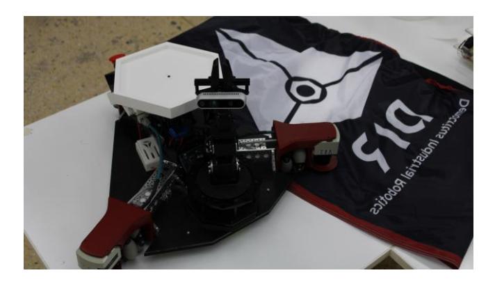
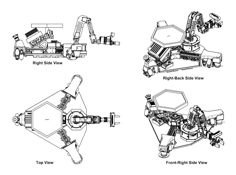
General characteristics of TALOS: The robotic platform has a triangular shape, three omni-wheels, which make the robot move agilely in the arena, and two laser scanners. The two laser scanners are placed on the two front edges of the robot and offer a 240° field of view. The superstructure of the robot has been built using Actobotics® parts, which contributed to:
- Making a innovative shape.
- Manufacturing the whole robot around them.
- Making sure that there is flexibility for future upgrades.
The rest of the parts where made with the use of 3D printing, CNC, and Laser cutting, with industrial and professional standards. The mechanical components of the robotic platform were designed using Fusion 360®. The main reason for doing so is the cloud-based software, which enabled the team's members to work remotely, from home, during the COVID-19 pandemic. All the mechanical parts were analysed using Fusion 360® Simulation before manufacturing. The full robotic platform is shown in the schematics in Fig. 2.
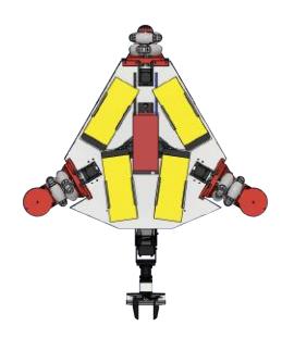
Soon after the completion of the robot superstructure and substructures, a major problem arose: the placement of the batteries. In order to alleviate this, the Product Design sub-team alongside the Electronics sub-team did a comprehensive design analysis, regarding the weight distribution, and battery design. After a lot of trial and error, and experimenting with different types of batteries and configurations, the team came up with a solution: The best placement of the batteries would be under the metal substructure, encased inside a 3D printed base. The battery system would consist of a BMS and 4 LiFePo4 batteries in a 4s1p configuration.
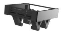
Along the way, after one of the regular quality control inspections, it was revealed that Jetson's pins are prone to accidents. So, the team managed to solve this issue by designing a pop-in/out case. This resulted in a much safer work environment and a future-proof design.
Structural & Thermal Analysis
In order to make sure that said platform is made with the utmost precision and functionality, the team utilised its most useful asset: The technical knowledge of its manpower. Nowadays, in order to make a high quality design, Design Engineers use simulation techniques. The field of computational mechanics is one of the most interesting ones, since it allows engineers to study and predict the behaviour of different structures, when loaded, by using models simulated into computer software, governed by the principles of mechanics. Computational mechanics is a sub-field of theoretical and applied mechanics that goes hand in hand with Computer-Aided Engineering (CAE) software. CAE software utilises numerical techniques, such as Finite Element Analysis (FEA). In order to solve the mathematical model of the analysed component, these programmes use direct and numerical methods – depending on the type of the finite elements (finite elements associated with second degree or higher polynomials cannot be solved using the direct method). The mathematical model of such analysis can be derived from the Virtual Work Principle. This part of the process is called main analysis and the most prominent solvers are:
- ANSYS
- NASTAN
- ABAQUS
In addition, the Computer-Aided Software includes pre-processing and postprocessing procedures, since the preprocessing is relevant to the application of external loading, the implementation of boundary conditions, and the meshgeneratorm, while the postprocessing has to do with the calculation of stresses and strains, as well as the reaction forces due to boundary conditions. The engineer must assess the results extracted from the analysis and this process consists of the classification of the finite elements into the following categories:
– Rod Elements – 1D
- Beam Elements 2D & 3D
- Plane Elements 2D (plane stress & plane strain implementation)
- Shell Elements 3D
- Solid Elements 3D
Besides those, it must, also, be mentioned that the structural analysis can include some additional phenomena. The current CAE programmes offer structural engineers the opportunity to simulate transient analysis problems, as well as non-linear problems due to the material properties and large deformations.
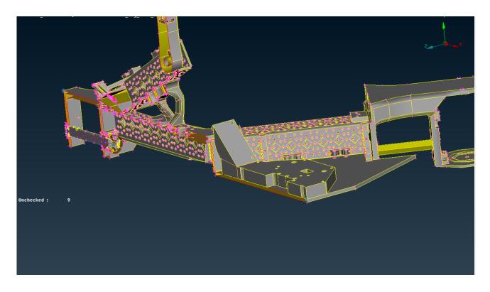
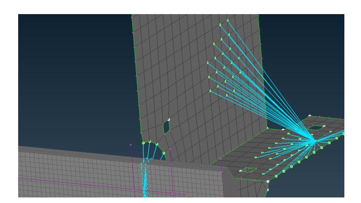
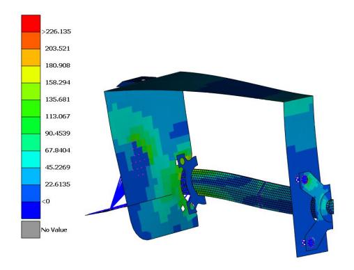
Structural Analysis: The design of the robot components has been done utilising Autodesk Fusion 360®. Moreover, the 3D model was imported into the ANSA software (as a step file) and the whole model, as well as some assembled components, have been structurally analysed using the programmes of BETA CAE Systems Corp. Specifically, this software includes:
– Preprocessor (ANSA)
– Solver (NASTRA)
– Postprocessor (META)
The engineer can tweak the geometry, meaning that they are able to improve the shape of some faces. Some thin model parts can be modeled as shell faces. For this purpose, this mesh generator is based on the Mindlin-Reissner plate theory. Regarding the volume mesh, the software is able to create solid mesh using some existing meshed faces. There is also the batch mesh function, which is an automated process that creates a mesh for the selected parts, while taking into account specific requirements associated with the mesh quality criteria and the target length of the meshing. An important feature of this software is that it can identify volumes into the designed model, which is very useful in order to fix broken meshes. Furthermore, as for the the main analysis, the engineer must decide what is the suitable analysis type, based on the application of a load and the constraint of some nodes. The solver tab (NASTRAN) has a lot of functions which help in the model-design of the external loads exerted, and the boundary conditions. After the completion of this step, the results can be extracted, then imported into the postprocessor interface.
In this way, the DIR-team is able to predict the resilience of TALOS, based on the material properties of its parts as well as the shape of its designed model. As a result, Assessing whether the designed are adequate for their intended use is possible.
Electronic Section
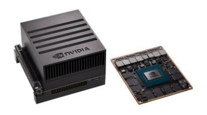
Electronic Hardware: The main processing unit of TALOS is NVIDIA's™ Jetson AGX Xavier® developer kit. Thus, the main AI robotics applications are being developed and deployed, end-to-end. It has a purpose-made CPU designed for running AI models on autonomous machines such as drones, robots, and autonomous vehicles. It is capable of delivering the performance of an equivalent high end workstation GPU in a much more agile package with very low power demand.
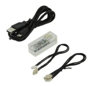
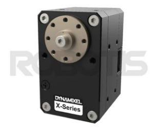
DYNAMIXEL® motors are used in the omni-wheels for drive and steering. Stable power is supplied to them by the power hub via a U2D2® board. The U2D2® board, also, supplies control signals to these motors. Another U2D2® and DYNAMIXEL® motors set is used for the power and control of the TA-LOS's Robotic Arm, a WidowXL Arm.
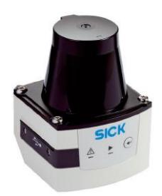
Furtherore, another important type of components includes the SICK™ TiM561® Lidar sensors. The team utilises two of them, on the basis of the applications they are typically used for, such as collision avoidance for automated guided vehicles (AGV), object measurement and detection, monitoring of objects in the field of building automation, pallet detection, and navigation of automated guided vehicles (AGV). The technical features they were chosen for are:
- They are able to monitor an area of up to 1 470 m2 with just one sensor.
- High ambient light tolerance due to HDDM technology.
- Rugged housing with up to an IP67 enclosure rating.
- Low power consumption (typ. 4 W).
- Compact design with a housing height of just 86 mm maximum
- Long sensing range of up to maximum of 25 m.
- Integrated Ethernet interface.
- Industry-standard design and M12 male connector.
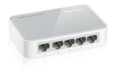
The TL-SF1005D® network switch has been selected for providing an easy way to extend wired networks. It has a relatively small footprint, low power consumption, data is being processed at 200 Mbps thanks to its full duplex mode, and all of its five ports are able to support auto-MDI/MDIX protocols, making its use suitable with the lidar sensors.
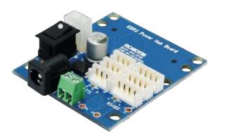
The team's robotic platform uses servo type motors. The DYNAMIXEL® servomotors are robot exclusive smart actuators with fully integrated DC Motor + Controller + Driver + Sensor + Reduction Gear + Network in one DC servo package-module. The DYNAMIXEL®-XH / XM Series offers a variety of control techniques, based on high-performance current sensing algorithms through the integration with a U2D2® and a U2D2® Power Hub Board.
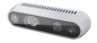
The camera used for the robot's computer vision capabilities is an Intel™ RealSense D435®. It is a well-known and widely used vision sensing product combining an Intel™ module and a vision processor into a small form factor. Paired with highly customisable software, the D435 proves to be a low-cost solution, which is lightweight and powerful, enabling the development of nextgeneration sensing solutions, that can study and interact with their environment, while offering a simple out-of-the-box setup. Intel™ RealSense SDK 2.0® software provides an on-chip self-calibration option for the D435 stereo camera, that allows full-axial camera calibration, in less than 15 seconds, without the need for specialised targets, making it ideal for integration with TALOS' systems.
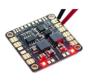
The power for the whole robot's circuit is distributed through the Matek™ Power Distribution Board® and its BECs. The input has a maximum value of 26VDC and its output is divided to 5V and 12V of direct current and to 4 ESC ports of adjustable voltage and continuous current. All the previously mentioned components except for Jetson®, are connected to the outputs of this board.
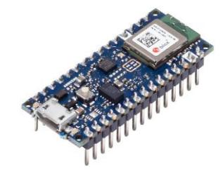
The latest addition to DIR's robotic platform was an Arduino™ Nano 33 BLE®, which is used as an Inertial Measurement Unit (IMU).
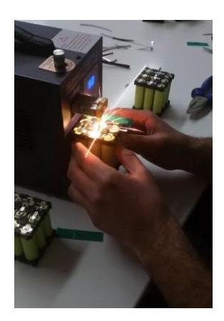
Power supply & batteries: After inspecting the power consumption of every electronic component, the team found out that the nominal voltages that we needed are 11.1V for most of the running parts of TALOS. After some research, it was found out that the best way to power all of these components, is by manufacturing battery packs with Lithium-ion cells. With the help of two of the team's sponsors, the team got 300 18650 Li-Ion batteries. A very thorough power analysis was made and the conclusions were that 3s3p packs were the ideal solution. The steps followed are:
- The voltage and the maximum current, that every component can draw was verified and put into a spreadsheet. Thus, the Wattage of TALOS was found.
- Then the batteries' spreadsheets were researched to find their nominal voltage and capacity.
- Using the last previous two (2) steps, the optimal number of batteries was computed, in order to power up the robot for a given amount of time.
- A Delta SOC of 0.4 was also used for further calculations, to keep the packs healthy, and found a new number of needed batteries.
- Since most of the electronics onboard use 12V it was decided to connect 3 batteries in series, producing a nominal voltage of 11.1V which was upped to 12V using a step up converter. The battery packs were made using a spot welder and nickel strips. To prevent uneven charge, a BMS was, also, added to each battery pack.
- The battery packs then were connected on the power hub, which suplies he robot's systems. But since Jetson AGX Xavier® works on 19V, the output of the power hub had to boosted. So, another step up converter was used.
- Finally the battery packs were insulated using kapton tape and electrical insulating tubes. After that, the robot was powered by interchangeable battery packs, that can last up to 6 hours on medium use or 4 hours on "full throttle".
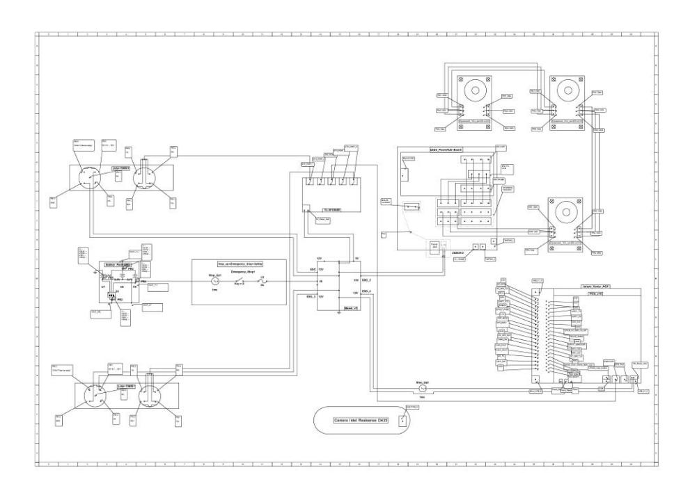
DIR, at that time, used circuit simulation tools to create a schematic of TA-LOS' power supply and distribution.
Further Modifications
Project Electrify: Being Electrical and Computer Engineering students, some of the team's members have adequate knowledge to create Custom PCBs. The Electrify DIR project, is the complete reformation of the robot's electronics systems, with the ultimate goal of creating a very capable system for TALOS. This will include 3 main axes, which aim for the best and most efficient implementation of the ideas governing the robot:
- Integrating the robot's boards into a single-board design, that includes all of them, with a design that allows for fast, safe, and efficient debugging and repairs.
- Redesigning the energy autonomy system of the robot, with new batteries, batteries' management system and powering modes, always within the < 500W h limit.
- Creating a smart handheld controller for the easier, faster and more efficient handling and monitoring of TALOS.
Integration of boards: At this part the team aims to create a single board, with a custom design by us, which will include if not, all at least most of the sub-boards that are:
- Matek™ Power Distribution Board®
- TP-Link™ Switch
- IMU
- U2D2®
- USB-Hub
- Step-Up Converter for Jetson®
To achieve maximum functionality and utilisation of the new overall board, the team set some necessary goals and conditions, the most important of which are:
- Along one of the sides of the new board design, it is deemed necessary to have contacts pads, output exits, surface pins, pogo pins or something similar depending on the needs, the format and the characteristics of the measurements. This way, the various electronics of the board can easily be monitored, verified or repaired when damaged.
- It is recommended that the current Matek™ board [MINI POWER HUB W/ BEC 5V and 12V] should be replaced with a better PDB (Power Delivery Board), specifically: Matek™ XCLASS® PDB FCHUB-12S. This PDB has better features than the current one, with the most important being: better current stabilisation, BEC 5V and 12V with maximum currents of 5A/max 6A and 4A/max5A, and over-current protection with auto-recovery, against 3A and 2A respectively.
Battery System Redesign :Upon overall observation of extremely high volatility, the possibility of serious accidents, the absence of vital technical characteristics, and the practical misfunctions of the current power system -in contrast to its theoretical plans-, it was deemed necessary to upgrade the power system of the robot. Specifically, the design of and upgrade to one whose technical characteristics of each part are full, analytical and in depth. The new power system had to have great operational stability, accuracy, safety, smaller chances of an accident due to misuse, and smaller chances of chemical fires. It had to give us the ability to monitor the real time power usage, the remaining capacity, both virtual and physical switches, and fail-safes.
Benefits: The new, upgraded, battery system would mean that, in the short term, the team would have a fully functional and fully integrated, closed battery system, ready to use, without having to actively look out for the batteries, since the new system would be designed with high performance components and the utmost attention to detail. In the long run, this meant the creation of a high performance, low maintenance battery system capable of working continuously for a very long time, with great stability, exceptional operational safety, long autonomy and high durability against improper use and environmental factors that decrease the operational life of batteries. The new system would also have immunity to health hazards, even in the event of battery failure.
The parts - the resources
This includes the parts that make up said system.
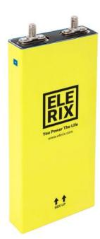
This Lithium Iron Phosphate type battery cell, shown on Fig.19 is the basis for the upgraded power system of the robot. 4 such cells in series are used, each of which outputs 3.2V and has a capacitance of 25Ah, therefore there are 12.8V at the BMS input. With this configuration the total capacity is 4 × 3.2V × 25Ah = 320W h (four is because of the four cells).
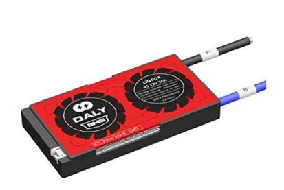
This BMS, shown on Fig.20, is the brain of TALOS' intelligent power system. This is facilitated, through an intelligent management environment, whose 3 main processes are necessary for the smooth operation of the robot. These are:
- Charging, with the desired voltage and current values.
- Discharging in way, that is healthy for the batteries, as well as setting the maximum current limits.
- Balancing the battery cell voltage and capacity to be the same for all the batteries.
At the same time, it performs secondary processes, extremely helpful for the robot, the most important of which are:
- The full setting of charging and discharging limits either automatically, by entering its battery, or manually.
- Monitors the condition and characteristics of each battery. Monitors the charge level, the capacity and the output voltage of each battery.
- Consumption measurements in real time as well as logging it automatically
- Selecting settings and sending the metadata via Bluetooth to a special application either on Android® or iOS® or via UART/RS485 on a computer.
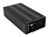
The MEANWELL charger is the way the batteries will are charged, so as to make sure the batteries are charged safely every time. It is a high performance, compact size charger of 2 or 3 stages of charging, with dual certification of 62368-1, 60335-1/-2-29.
TALOS' Handheld:In order to control TALOS on the go, a handheld controller is currently being designed. It is going to keep the team updated about the robot's performance such as. It is, also, going to help with the initial mapping of a new environment and visualise the robot's view of the environment, among other things.
Reconstruct Parts: When the robot was initially made, some of the parts were made of plastic 3D printed materials, such as PLA, that are by definition weaker than metals. A further teams's goal is to replace all of the 3D printed parts by heavy duty aluminium, or even redesign the robot with the use of carbon fiber, in order to decrease its weight and gain structural strength, without losing its durability.
Marketing
Marketing
Graphic Design
DIR's creative department was involved in the design of the team's logo, the flyer and the team's promotional material.
As far as the logo is concerned, the team's inspiration was the design of its robot, Talos. Looking at it and focusing on its centre, DemocritusIndustrialRobotics (Marketing, Programming, Construction) finds a small nut that constitutes the core of the team and sets in motion the three departments of. The three departments, rendered in triangular shapes, form a circle around the core in order to suggest that the departments are moving on the same trajectory in order to achieve their common goal.
In addition, DemocritusIndustrialRobotics (Marketing, Programming, Construction) established its colour palette and continued to create unique and original graphic designs, giving a new air to its social media profile.
A similar design strategy was followed for the brochure which is dominated by the same creative plan as the social media image.
The success of the team's creative department is evidenced by the brand's resonance both within the local community and beyond.
Promotion
The marketing department, in order to promote the work of the team and to introduce the robot, Talos, to the society, is constantly looking for and finding new ways to promote DemocritusIndustrialRobotics (Marketing, Programming, Construction)'s work and its goals.
Website & Social Media: The marketing department has maintained the team's social media profiles (Facebook, Instagram, Linkedin) renewing their structure in order to attract new people and maintain the interest of the team's supporters. More specifically, on Instagram, which is the main social media of the team, the marketing department thought of creating some thematic days, which will start to be posted systematically from the beginning of April.
These thematic days are as follows:
- Wallpaper Wednesday: it's a story that followers will be able to screenshot and use as wallpaper on their phone.
- Throwback Thursday: is a post in which visual material from actions in which the team has participated will be uploaded.
- Sponsor Sunday: is a story in which the team's supporters will be thanked for their support in Talos' journey to the competition in July 2024 in Eindhoven, the Netherlands.
Promotion with a specially designed stand at the 87th Thessaloniki International Fair: The 87th edition of the Thessaloniki International Fair was held once again, in early autumn, from 9 to 17 September 2023, and it was an important, institutional exhibition event that is interwoven with the history of both the economic and cultural development of the country and of South-Eastern Europe in general. The sectors focused on at last year's IET present the new market proposals in the fields of technology, innovation, environmental protection, energy, education, start-ups and e-government. DIR and Talos had a stand there.
Participation in a robotics conference: On Thursday 12 October the team participated in the dialogue panel entitled ''Upgrading the innovation ecosystem through educational robotics'' at the Amphitheatre of the Department of Civil Engineering of the Democritus University of Thrace.
DemocritusIndustrialRobotics was given the opportunity to participate in this dialogue panel, where it discussed its idea with entrepreneurs, educators and business executives. DIR received many congratulations for its idea, strengthened its network of future partners and met ambitious young people who want to join the world of robotics.
Participation and Workshop Organization at TEDXDUTH: The saying attributed to Heraclitus "Everything is always changing, never staying the same" captures a timeless human concern and dilemma between resistance and acceptance of change. Thus, TEDxDUTH 2023 tried to highlight the nature of change and its impact on the human experience, as well as how humans can manage it. On Saturday 4 November 2023, at the University Campus of Komotini, DIR was there with an original workshop dedicated to the introduction of Arduino.
Display with a specially designed booth at the 1st Automation & Robotics Exhibition in Greece: The company PL Events Organizers of the successful Syskevasia, Plastica & Chem Exhibitions, with 37 years of experience and know-how, will hold for the first time in Greece the A & R EXPO '24 on 12- 14 April 2024 at Athens Metropolitan Expo. A&R EXPO visitors will have the opportunity to see all kinds of automation (industrial, technological, domestic, agricultural, marine, smart, etc.) as well as the whole spectrum of the robotics industry (agricultural, medical, educational, domestic, energy, laboratory, packaging, aerial, services, Industry 4.0, IoT, etc.). DIR and Talos will have a booth there.
Screening in a specially designed area at the ECESCON15 conference: The Electrical and Computer Engineering Students' Conference (ECESCON) was launched in 2007 in Athens. The participants are Greek future engineers studying in the fields of Power Systems, Systems and Control, Electronics and Computer Engineering, Telecommunications and Computer Science. Each year, ECESCON exceeds 1500 participants and creates three days full of activities that aim to bring together students from all over Greece who share a passion for Electrical and Computer Engineering and wish to keep up to date with the latest developments. DIR and Talos will have a booth there. DIR, also, had booths in ECESCON 14, in Volos, and in ECESCON 13, in Patras.
Participation as judges in the Minoan Robotsports Competition Global Olympiad: HELLENIC EDUCATIONAL ROBOTIC ORGANIZATION – HERO is a non-profit organization whose goal is the proper development and spread of Educational Robotics and STEAM in Greece. The object of HERO is the organization of World Robotics Competitions in Greece, as well as nonprofit actions, exhibitions, festivals, etc. in the field of educational robotics, new technologies and STEAM. For the first time from 26 to 29 April 2024 at Crete a competition that focuses on Sports Robotics is happening. DIR is pleased to be there in the role of a judge evaluating the participating teams that are invited to build Athletes - Robots.
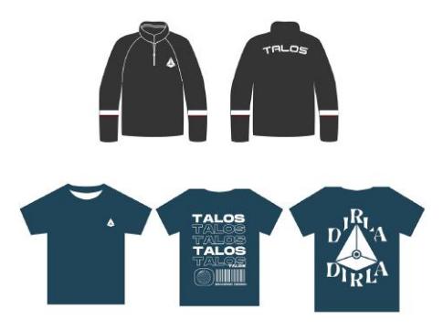
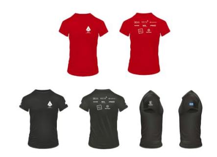
Create a new uniform: As part of the team's development in 2023-2024, DIR completed the design of three new daily uniform designs for the team members and it is gradually completing the design of the official team representation uniform.
Promotional Video: DIR's goal is to create a video that will showcase the evolution of the team and Talos from its first steps to now.
We aim to promote the team in the media.
Web Design
The development of DIR's website will be carried out using the free platform ''Wordpress'' as it is a free and open source software and is widely used for the creation of websites, blogs and even applications. This platform was chosen by the relevant department of DIR because of its simple way of use through its pull and drug feature. Through this website everyone will have the opportunity to discover who DemocitusIndustrialRobotics is, what is its purpose as well as who are the persons behind Talos. At the same time this website will have an informative character whereby the interested person will be able to find out about future events that the group is going to organize or participate in the near future. Besides, the interested parties will have access to rich audiovisual material from the events in which DIR has taken part. Finally, each user will be given the opportunity to get to know DIR's supporters in this magical journey of robotics through their own separate tab on the website.
Programming
Programming
Introduction
The Programming Department's purpose is to programme the robotic platform (Talos), so that it succesfully completes every task of the RoboCup@Work League. In order for this to be achieved, the Robotic Operating System (ROS) is used. AMCL, MoveIt!, SLAM, rviz, gazebo and other open source packages contained inside ROS are extensively used by the programming department. The ROS distribution, that is used, is Melodic Morenia. The programming languages of choise are: Python (primarily), and C++ (secondarily). The programming department is divided into five sub-teams: Autonomous Navigation, Arm Manipulation, Vision, State Machine, and Simulation.
Autonomous Navigation
The Autonomous Navigation (or simply Navigation) sub-team's purpose is to map Talos' environment, merge the sensors' measurements, and use localisation and autonomous navigation algorithms to accurately measure the robot's position, find the optimal path to a desired destination and guide the robot there. The navigation system is based on the ROS navigation stack. The following paragraphs are a description of the main components that constitute navigation and are used in the same order as they are presented.
LiDARs: In a Laser Imaging, Detection, and Ranging (LiDAR or Lidar) system, laser beams are emitted from a rapidly firing source. These beams travel to the environment, in which a robot may move, and reflect on surfaces like wooden obstacles, walls and workstations. Then, the reflected beams return to the lidar sensor, where they are recorded. A lidar system measures the time it takes for an emitted beam to travel to an obstacle and back. That time is used to calculate the distance between the lidar sensor and the obstacle. The working principle of a lidar system is similar to that of a radar or a sonar. The difference between them is the type of wave that is used. Radar systems use radiowaves or microwaves, sonar systems use sound waves, and lidars use laser beams. TALOS has two lidar sensors.
Merger: Each one of TALOS' lidars publishes in its ROS own topic. An open source ROS node called "ira laser tools" is used to merge these topics into a single one.
LiDAR Noise Filtering: Lidar echo signals are easily contaminated by noise, which severely affects the retrieval accuracy and the effective detection range of the lidar system. Close proximity noise (noise relevant to an area ≤ 1.5m around the robot) has been the culprit of many issues the team has faced. This is why, DIR created a range filter algorithm which calculates the median of a region, defined by a number of rays, and then checks if any element of that region deviates more than 20% from the median. In that case, this element is replaced by another. The new element is located in an extreme distance from the robot (e.g. 10m). The output of this filter is published in a ROS topic and used when needed.
Mapping: For navigation to take place, a description of the environment is required. Mapping is the process where the robot explores the environment (oftentimes manually) and constructs a corresponding 2D map. Simultaneous Localisation and Mapping (SLAM) algorithms, like gmapping, are used. SLAM is able to produce a map -in pgm format- using the Lidars' laser scans. GNU Image Manipulator (GIMP) is, also, used to correct mistakes made by SLAM.
Sensor Fusion and Extended Kalman Filter (EKF): In dynamic and competitive environments, ensuring precise and agile navigation is paramount. To achieve this, integrating data from multiple sensors to offset the limitations of individual sensors is essential. This section outlines a system that fuses data from an Inertial Measurement Unit (IMU) and wheel odometry using an Extended Kalman Filter within the Robot Operating System (ROS) framework, aiming for enhanced navigation accuracy.
An Inertial Measurement Unit (IMU) is a critical sensor in robotics, providing vital information about the robot's orientation, angular velocity, and linear acceleration. Consisting of a combination of accelerometers, gyroscopes, and sometimes magnetometers, IMUs help in estimating the robot's pose and movements relative to its starting position. DIR uses an Arduino Nano 33 BLE, which has a built-in LSM9DS1 IMU. This is a 9-axis IMU that comprises of a 3-axis magnetometer, a 3-axis accelerometer and a 3-axis gyroscope. These values, however, do not directly provide information about the robot's position and orientation, which need to be derived. Specifically, DIR is interested in the x,y coordinates, and the z-axis angle of the robot, in the 2D plain, which are derived from the IMU's measurements with mathematical equations. In ROS, the IMU data is published on the /imu topic, utilising the sensor msgs/Imu message type. This message includes comprehensive details such as the orientation (expressed as quaternion components x, y, z, w), orientation covariance, angular velocity, angular velocity covariance, linear acceleration, and linear acceleration covariance.
Wheel odometry involves estimating the robot's pose and velocity based on the rotation of its wheels. This method is particularly useful for robots navigating on relatively flat and non-slippery surfaces, where the wheel rotations can be accurately translated into movements in space. In ROS, wheel odometry data is published on the nav msgs/Odometry message, which is published on the /odom topic. This message provides the robot's pose, which comprises its position and orientation, alongside its twist, capturing both its linear and angular velocity, all within a specified frame of reference. Similar to the IMU data, the odometry message also includes covariance matrices for the pose and twist, reflecting the uncertainty of these measurements.
However, despite their utility, both IMU and wheel odometry sensors are subject to noise and inaccuracies that can introduce significant errors in pose estimation over time. This inherent noise underscores the necessity for a more advanced method to fuse these data streams effectively, thereby enhancing the reliability and accuracy of the robot's navigation system. For these reasons, the members of the Navigation sub-team have chosen to employ the Extended Kalman Filter (EKF), which is a statistical filter that operates recursively in a prediction and update block.
More specific, in Talos' case, the state is expressed as the position (xt), (yt) and orientation (yawt) in a specified reference frame. The state prediction step is fundamentally dependent on the IMU data, which provide the control vector, at a frequency of 104 Hz, and is consisted of the linear velocity (vt) and angular velocity (ωt). Among the various models available, the Constant Turn Rate and Velocity (CTRV) motion model has been selected for its efficacy in capturing the dynamics of vehicular motion. The update phase of the EKF relies on odometry data, serving as the measurement vector to correct the predicted state. This odometry data, which includes the robot's pose (xt), (yt), (yawt) is sampled at a frequency of 15 Hz. By integrating these measurements, the EKF refines its state estimate, improving the accuracy of the robot's perceived position and orientation.
Adaptive Monte Carlo Localisation (AMCL):Now that we possess the map and a good estimation of the robot's pose, we can run the localisation algorithm. Localisation means the robot must accurately infer it is located in the map and our algorithm of choice for this purpose is AMCL. As its name suggests, Adaptive Monte Carlo Localisation uses random sampling of the so-called particles (i.e. points in the map, with pose information, that the robot could be located at) to adapt the assumption of where the robot is located. AMCL takes as input the pre-scanned map, the current LiDAR measurements, the current EKF pose measurement and outputs the assumed location (and orientation) on the map based on the available sampled particles. It does this by figuring out which of the available particles match the current measurements. The estimation is improved progressively, meaning that the algorithm hones in on the true location of the robot as it moves around and observes more of its surrounding environment. We can execute the AMCL algorithm for either the static case -where the map is unchanged- or the dynamic case -where dynamic elements have been introduced inside the map like a new obstacle-.
Arm Manipulation
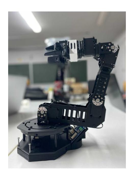
The Arm Manipulation (or Arm) sub-team's purpose is to programme the robot arm (or manipulator), so that it goes to an object's initial position, it grabs the object and gets it to its desired position.
The robot arm which has been chosen is the WidowXL Robot Arm Kit. This decision was based on several factors, such as: the cost, the maximum reach, the total payload etc. Up to the point of ordering, tests were made on a simulation, based on a step CAD file of the arm. Since the documentation for the WidowXL was deficient, customising and manually creating the URDF model and the MoveIt! configuration of the arm was necessary. The motion of the arm is controlled through the move group python interface. More specifically, it receives a Pose Goal (x,y,z coordinates and orientation) for the end effector from the camera attached to the manipulator. By using inverse kinematics, the move group plans a collision-free path to the object. Finally, the manipulator executes the planned motion in order to grasp the target and place it to the desired place.
In the immediate future, DIR plans to replace the WidowXL arm with the MyCobot 320 M5 arm by Elephant Robotics. This will address several technical problems the team has had.
Vision
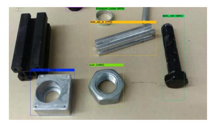
The Vision sub-team's purpose is to train a computer vision model, which recognises every object that has to be recognised according to the RoboCup@Work rulebook, and pass the necessary information to Navigation or Arm packages.
The approach utilises a combination of deep learning techniques, traditional computer vision methods, and integration with the Robot Operating System (ROS) to achieve robust performance. Initially, a Deep Neural Network architecture based on YOLOv4, with the Darknet backbone, is trained, on an extended dataset, to recognise the objects of interest, yielding satisfactory results with an average Intersection over Union (IoU) of 79.64% and mean Average Precision (mAP) of 98.97%, at an IoU Threshold of 50%. Additionally, traditional computer vision approaches are employed to address challenges such as object orientation, cavity detection, and barrier tape localisation, with ongoing efforts to enhance their reliability. Furthermore, a barrier tape localisation algorithm, utilising OpenCV and point cloud filtering, is developed and integrated into the common costmap, in order to facilitate obstacle avoidance during robot navigation. In pursuit of performance enhancement, our team is currently testing YOLOv5 and YOLOv8 models for deployment on the Jetson Xavier AGX platform. This endeavour aims to leverage the computational power and energy efficiency of the Jetson Xavier AGX to achieve real-time object detection with minimal latency, thereby augmenting the autonomy and responsiveness of the robotic system. Through rigorous testing, optimisation, and integration efforts, we strive to advance the capabilities of our computer vision system, ultimately enhancing the competitiveness of our team in the RoboCup@Work competition.
State Machine
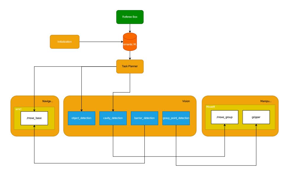
The robot's behaviour is dictated by the state machine overview shown in Fig. 28. The team went with a simple approach, trying to set a modular framework that satisfies the basic requirements of the underlying tasks, but at the same time allows room for future improvements. The final behaviour is split into five main sub-behaviours that communicate required information with each other:
- The Initialisation behaviour, Responsible for receiving the map, alongside with its semantic information and localising the robot on it.
- The Task Planner, Receives the generated tasks from the referee box and optimises their order of execution using A* graph-based search. It is also responsible for prioritising the manipulation of objects in the pick and place pipeline.
- The Navigation behaviour, which is essentially an implementation of the move base functionality and ROS's AMCL package.
- The Vision stack, consisting of a set of states calling actions/services that
implement tasks such as object/ cavity detection and are callable by their respective clients.
- The Manipulation behaviour, which receives an input from the Vision stack and with the help of MoveIt!, controls the robotic arm to manipulate the requested objects.
The general goal for the state machine is to create a robust robot behaviour that is not prone to failures, by adding error handling capabilities and task rerouting. However, as of the conception of this paper, no such functionality has been included for demonstration. The above implementation was achieved in FlexBe.
Simulation
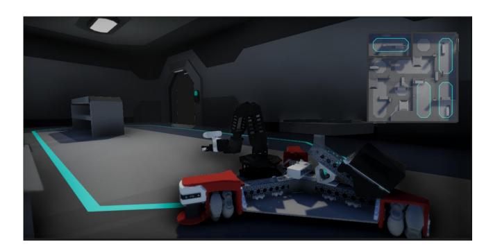
TALOS was brought to the simulation virtual environment, with the use of Gazebo and Fusion 360®. A proper virtual environment is used for the robot's simulation. When modelling a robot in a simulation, a representation of its visual meshes, collision meshes, and physical properties is needed. Visual meshes are required to render the robot realistically. Collision meshes are required to calculate collisions between the robot's "links" (the rigid parts, that connect joints), other objects in the environment, and the robot itself. These meshes are typically less complicated than their visual counterparts to allow faster collision-checking, which tends to be compute-intensive. Finally, the robot's physical properties, like inertia, contact coefficients, and joint dynamics, are required for accurate physics simulation — that is, for computing how forces on the links result in changes in the robot's state, e.g., pose, velocity, or acceleration. ROS development workflow offers a standardised method for describing all these properties: the Universal Robot Description Format (URDF). URDF files are XML files which specify these visual, collision, and physical properties in a human-readable mark-up language. URDF files can also include mesh files for specifying complicated geometries.
Having a functional and realistic simulation environment, is imperative, because it enables DIR's programmers to test their code when the physical robot is not available. For this purpose, there is a whole sub-team of the Programming Department, called "Simulation", whose purpose is to maintain an up to date simulation environment, as well as to seek better ways to simulate TALOS and its environment. DIR has the long-term goal to replace Gazebo with Unity®, using Unity's link to ROS.
Conclusion
In the tenure as a student robotics team, the members of DIR have consistently demonstrated a commitment to excellence and a passion for the field of robotics. Despite the challenges, DIR have endeavored to push the boundaries of our capabilities and contribute meaningfully to the broader robotics community.
DIR. Do It Right. Do It Robotic.
References
- TALOS. (2024). https://dir.com.gr/
- Fusion 360®, Autodesk. https://www.autodesk.com/products/fusion-360/overview
- ANSA, BETA CAE Systems Corp. https://www.beta-cae.com/
- NASTRAN, Siemens Digital Industries Software. https://www.plm.automation.siemens.com/global/en/products/simcenter/nast...
- META, BETA CAE Systems Corp. https://www.beta-cae.com/
- NVIDIA Jetson AGX Xavier, NVIDIA. https://www.nvidia.com/engb/autonomous-machines/embedded-systems/jetson-...
- DYNAMIXEL Corp. (2024). https://www.dynamixel.com/
- SICK™, 2024. https://www.sick.com/ag/en/catalog/products/lidar-and-radarsensors/lidar-sensors/tim/tim561-2050101/p/p369446
- TP-Link, 2024. https://www.tp-link.com/gr/business-networking/soho-switchunmanaged/tl-sf1005d/
- Intel RealSense, 2024. https://www.intelrealsense.com/depth-camera-d435/
- Matek, 2024. https://www.mateksys.com/
- ELERIX Lithium Cell LiFePO4 Prismatic 3.2V 25Ah, 2024. https://www.example.com/ELERIX
- Daly BMS 30/40A, 4S 12V, +BT +RS435, 2024. https://www.dalybms.com/
- MEANWELL Battery Charger LFP 120W 12V/6.8A (Max 14.4V), 2024. https://www.meanwell.com/webapp/product/search.aspx?prod=NPB-120
- Robot Operating System, Wikipedia. https://en.wikipedia.org/wiki/Robot Operating System
- Nano 33 BLE, Arduino Docs. https://docs.arduino.cc/hardware/nano-33-ble/
- IMU Message, ROS Docs. https://docs.ros.org/en/noetic/api/sensor msgs/html/msg/Imu.html
- Odometry Message, ROS Docs. https://docs.ros.org/en/noetic/api/nav msgs/html/msg/Odometry.html
- Probabilistic Robotics, Thrun, Sebastian and Burgard, Wolfram and Fox, Dieter, 2005, MIT Press.
- gmapping, ROS Wiki. https://wiki.ros.org/gmapping
- GNU Image Manipulator, GIMP. https://www.gimp.org/
- Widow XL Robot Arm, Trossen Robotics. https://www.trossenrobotics.com/WidowXL-Robot-Arm
- Github. https://github.com/AltziTS007/widowxl gz.git
- myCobot 320 M5, Elephant Robotics. https://www.elephantrobotics.com/en/mycobot-320-m5-en/
- Codd-Downey, R., Mojiri Forooshani, P., Speers, A., Wang, H., & Jenkin, M. From ROS to unity: Leveraging robot and virtual environment middleware for immersive teleoperation. (2014)
- Nikita Vaneev: Building a virtual environment in Unity based on a robot's perception. University of Twente, Netherlands (2018)
- Unity Blog. https://blog.unity.com/technology/robotics-simulation-in-unity-is-aseasy-as-1-2-3 (Nov 2020)
- Github. https://github.com/Unity-Technologies/Unity-Robotics-Hub