S.R.B Team Description Paper
Dr.Ali Moarefian pour, Farhan Daemi Mojdehi, Padina Farokhian, Iman Moshtaghi, Taha Ahmadzadeh, Amir Ali Eskandari, Alireza Daemi Mojdehi
Islamic Azad University Science and Research Branch, Tehran – Iran
Abstract In this paper we represent and describe about Artificial Intelligence used in Industrial Robots and the advantages of the industrial robots to be smart. Today we know that the usage of robots in industry is so huge and it is improving very fast. We decided to build an industrial robot which can navigate to any place using the lidar system and bring objects from the production line and move it to other places needed. The object detection system is completely automatic using image processing algorithms and calculation of the position of the object in the space around the robot. With making this robot we experienced the three main part of science that are combined to each other to become a wonderful product. These three parts are Electronics, Mechanics and Programming
Introduction
Some of the old years, the S.R.B team participated in world Robocup competitions. S.R.B team started working on small smart soccer robots from 2008. In 2014 Robocup competition in Brazil S.R.B team had a very good Experience. In 2015 competitions the main structure of the robots is the same as last year. 2016 was the year that this team started it serios work in senior @Work league. Some requirements to reach this target are achieved by redesigning the electrical and mechanical mechanisms. Moreover, simple learning and optimization approaches are employed in the way of more dynamic play. This paper is organized as follows: First of all, the software architecture which includes our approaches in high level strategies, The Electrical design including ARM micro controller, and other accessories.
Mechanical Design
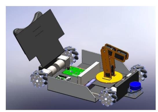
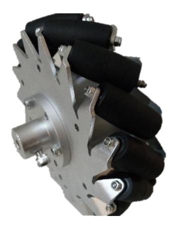
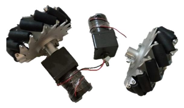
One of the main parts of our robot was mechanical systems. Motors and mecanum wheels designed on the circle that can be motion all the directions. We used Solid Work software for designing the main plat form of the robot. We designed the parts of robot and then we started to making it with different materials.
Hardware/ Electrical Design
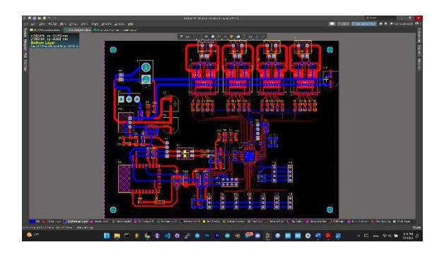
We designed a PCB with Altium Designer software and then we printed it and soldered the electronical parts of the robot. The most important part was ARM processor STM32F407. It has so many options like timers, Analog digital convertor and serial port and other things. For switch the motors we used L6203 drivers. Because it can ferry 4 Ampere electrical current.
The arm and griper
For design and construction, the arm with three degrees of freedom we used three DC motor with worm gearboxes and for the griper we used a servo motor.
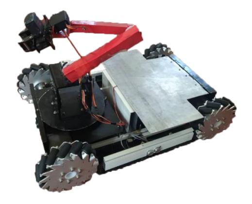
Image processing/Vision System
In imaging science, image processing is processing of images using mathematical operations by using any form of signal processing for which the input is an image, a series of images, or a video, such as a photograph or video frame; the output of image processing may be either an image or a set of characteristics or parameters related to the image. Most image-processing techniques involve treating the image as a two-dimensional signal and applying standard signal-processing techniques to it. Images are also processed as three-dimensional signals with the third-dimension being time or the z-axis. Image processing usually refers to digital image processing, but optical and analog image processing also are possible. This article is about general techniques that apply to all of them. The acquisition of images (producing the input image in the first place) is referred to as imaging. Closely related to image processing are computer graphics and computer vision. In computer graphics, images are manually made from physical models of objects, environments, and lighting, instead of being acquired (via imaging devices such as cameras) from natural scenes, as in most animated movies. Computer vision, on the other hand, is often considered high-level image processing out of which a machine/computer/ software intends to decipher the physical contents of an image or a sequence of images (e.g., videos or 3D full-body magnetic resonance scans). In modern sciences and technologies, images also gain much broader scopes due to the ever growing importance of scientific visualization (of often large-scale complex scientific / experimental data). Examples include microarray data in genetic research, or real-time multi-asset portfolio trading in finance.
The most important part of programing in this robot is image processing. To do this we used Open-CV library in C# language. The Open-CV library for C# is Emgu-CV. The commands are the same but the names have some differences. At first the robot should get to the object's table and then process on images that are getting from the webcam camera. After detect the object and find the place it is, it should catch it with its arm. For doing that it send's some commands to the AVR microprocessor with serial communication and the micro controller do them. After getting the objects it should carry them to somewhere else. Moving system is with distance detecting. We have some distance sensors around our robot that can detect the walls,
Navigation
We used a different camera under our robot that can detect the landmarks. To arriving the landmarks, we have a laser scanner that give us a 2D plan of the land and the robot can move to the landmarks with process this plans. Most laser scanners use moveable mirrors to steer the laser beam. The steering of the beam can be one-dimensional, as inside a laser printer, or two-dimensional, as in a laser show system. Additionally, the mirrors can lead to a periodic motion - like the rotating mirror polygons in a barcode scanner or socalled resonant galvanometer scanners - or to a freely addressable motion, as in servocontrolled galvanometer scanners. One also uses the terms raster scanning and vector scanning to distinguish the two situations. To control the scanning motion, scanners need a rotary encoder and control electronics that provide, for a desired angle or phase, the suitable electric current to the motor or galvanometer. A software system usually controls the scanning motion and, if 3D scanning is implemented, also the collection of the measured data. In order to position a laser beam in two dimensions, it is possible either to rotate one mirror along two axes - used mainly for slow scanning systems - or to reflect the laser beam onto two closely spaced mirrors that are mounted on orthogonal axes. Each of the two flat or polygonal mirrors is then driven by a galvanometer or by an electric motor. Two-dimensional systems are essential for most applications in material processing, confocal microscopy, and medical science.
References
- P.de Kok,N. Girardi, A. Gudi, C. Kooijman, G. Methenitis, S. Negrijn, N. Steenbergen, D. ten Velthuis, C. Verschoor, A. Wiggers, and A.Visser,"Teamdescription for RoboCup 2013 in Eindhoven, the Netherlands," Dutch Nao Team, Universiteit van Amsterdam & TU Delft, May 2013.
- N. Dijkshoorn, H.Flynn,O.Formsma, S. van Noort, C. van Weelden, C. Bastiaan, N. Out, O. Zwennes, S. S. Ot´arola, J. de Hoog, S. Cameron, and A. Visser, "Amsterdam oxford joint rescue forces - team description paper virtual robot competition - rescue simulation league - RoboCup 2011," Universiteit van Amsterdam & Oxford University, July 2011.
- C. R. Verschoor, A. J. Wiggers, H. R. Oosterhuis, and A. Visser, "Maneki-neko team description for iran open uav 2013 teheran, iran," Intelligent Robotics Lab, Universiteit van Amsterdam, February 2013.
- S. Negrijn, J. Haber, S. van Schaik, and A. Visser, "UvA@Work customer agriculture order - mid-term report," Intelligent Robotics Lab, Universiteit van Amsterdam, Science Park 904 1098 XH Amsterdam, January 2014.
- J. van Enk, "Navigating youbot through a rose field with A*,"Project Report,Universiteit van Amsterdam, Science Park 904 1098 XH Amsterdam, August 2013.
- S. Koenig and M. Likhachev, "D* lite." in AAAI/IAAI, 2002, pp. 476–483
- L. Dorst, I. Mandhyan, and K. Trovato, "The geometrical representation of path planningproblems,"Roboticsand utonomous Systems, vol. 7, no. 2, pp. 181–195, 1991.
- M. Phillips, A. Dornbush, S. Chitta, and M. Likhachev, "Anytime incremental planning with e-graphs," in Robotics and Automation (ICRA), 2013 IEEE International Conference on. IEEE, 2013, pp. 2444–2451.
- E. Corten and E. Rondema, "Team description of the windmill wanderers," in Proceedings on the second RoboCup Workshop, 1998, pp. 347–352.
- P. Jonker, B. van Driel, J. Kuznetsov, and B. Terwijn, "Algorithmic foundation of the clockwork orange robot soccer team," in Algorithmic Foundations of Robotics VI. Springer, 2005, pp. 17–26.
- A. Visser, J. Sturm, P. van Rossum, J. Westra, and T. Bink, "Dutchaiboteam: Technicalreportrobocup2006,"December 2006.
- V. Spirin, S. Soffia Ot´arola, and A. Visser, "Amsterdam oxford joint rescue forces - team description paper - virtual robot competition rescue simulation league - robocup 2014, jo˜ao pessoa - brazil," 2014.