Team Description Paper UNSW@Work RoboCup@Work 2024
Harrison Burns, Jasper Arnold, Mitchell Torok, Jack Adams
University of New South Wales, Sydney NSW 2052, AUS
https://robotics.cse.unsw.edu.au/unsw-work/
Abstract The UNSW@Work is a new team aiming to compete in @Work RoboCup 2024. Formed in late 2023 and based at the University of New South Wales in Sydney Australia, UNSW@Work consits of 4 members with expertise in mechatronics and computer science. Initial development has focused on producing a simple and efficient generalised software architecture, which allows for easy expansion and modification to accommodate new tasks. UNSW@Work uses a 4 wheel mecanum drive base equiped with a 6 DoF arm and in-house end effector for item manipulation. A 3D lidar is used for navigation while a depth camera attached to the arm is used for item identification and other perception tasks. All software has been developed in ROS2 Humble, with distinct packages to allow for efficient individual parallel development. So far the team has achieved basic task optimisation, autonomous navigation, localisation relative to a map, and item identification and collection. While there is still work to be done to be competitive, the team is confident this can be achieved before competition.
1 Introduction
UNSW@Work is a new RoboCup @Work team based at the University of New South Wales. The team consists of 4 members (Table.1), with a mix of undergraduate and postgraduate students. No member of this team has competed in RoboCup before, however, the team is experienced in mechanical, electrical and software implementations from other robotics competitions and projects. Formed in late 2023 the team has been hard at work, developing a competitive solution to compete in RoboCup 2024.
A custom robot has been developed for this task. The robot carries a UniTree z1 robotic arm, with an end effector developed in-house. An intel D435 depth camera is used for item detection and a UniTree L1 4D Lidar is used for robot navigation. The Robotic Operating System 2 (ROS2) Humble version is used for effective development and communication between separate sub-systems.
This paper discusses UNSW@Works progress and implimentation. First a discussion of our research and development (2), then a hardware and software description (3,4) of our solution and finally a discussion of higher-level concepts, including our design approach (5), influence from other teams (6) and future work (7).
Table 1. UNSW@Work team description
| Name | Task | Degree |
|---|---|---|
| Harrison Burns | Navigation, Perception | Undergraduate - Mechatronics |
| Jasper Arnold | Brain, Localisation, Task Optimiser | Undergraduate - Mechatronics, Computer Science |
| Mitchell Torok | Arm, Perception, Mechanical, Team Lead | Postgraduate - Mechatronics, Computer Science |
| Jack Adams | Perception, Inventory | Undergraduate - Mechatronics |
2 Focus of Research
As the team is developing and building up the fundamentals there has been no explicit work on novel research as of yet. However particular members of the team have research interests related to how online reinforcement learning (RL) can be applied to the @Work scenario. Research in the area has shown the potential for RL based systems to generalise and perform additional skills effectively [1]. As such our team is excited to explore how RL approaches can be developed to effectively collect and potentially use tools inside the @Work competition.
3 Hardware description
3.1 Overview
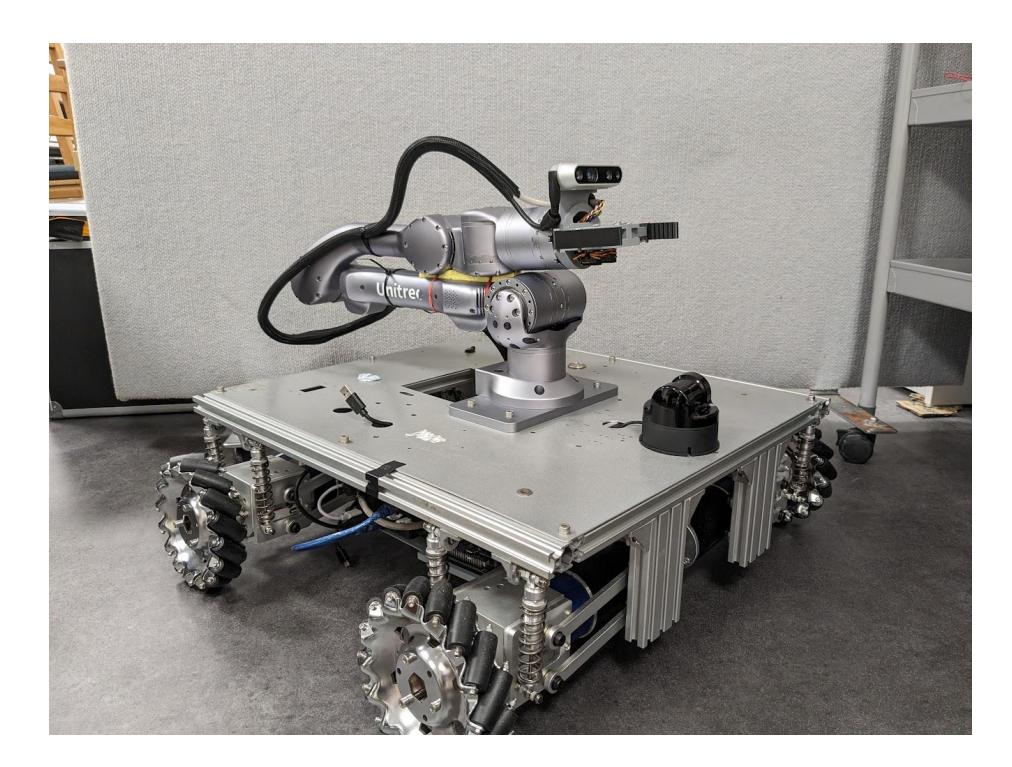
The development robot can seen in Figure 1, it is a 4 wheeled mecanum holonomic drive base with a Unitree z1 arm Unitree l1 Lidar and Intel Realsense D435 Depth camera. The supplied end effector was deemed not effective for the challenge of Robocup@Work, A custom design has been used instead. The robot pictured in Figure 1 is an initial prototype and would not be used in Robocup@Work. A smaller viable robot with the same equitment has been designed and in the process of being fabricated.
3.2 Drive Base
The Robot's drive base is a modified Mecabot Pro chassis supplied by RoboWorks [13]. It consists of four mecanum wheels with spring-damper suspension and independent drive motors. The system utilises the onboard IMU and motor encoders for Odometry estimation. The drive base, as seen in Figure 1, is relatively large compared with the competition arena at 225.5mmx541mmx581mm and thus increases the chance of undesired collisions in tight areas of the arena. To account for this, the drive base will be modified to shrink the footprint of the vehicle.
3.3 Arm and Manipulator
A Unitree z1 6 DoF robotic arm was selected for the system, it is capable of a 700mm reach and payload of up to 2 kg. We use a custom end effector that holds an intel real sense d435 and a parallel linkage jaw. The end effector seen in Figure 1 is a temporary prototype, A custom linear parallel jaw system has been designed and will be used.
3.4 Perception
As a primary source of environment sensing, the robot is using the UniTree 4D LIDAR L1. This LIDAR has a scanning FOV of 360°x 90°, a range of 30m and a measurement accuracy of ±2cm [11]. Compared to other LIDARs of similar specifications, the L1 has a compact form factor, giving the team several options for mounting [11]. The L1 also outputs data as a ROS2 PointCloud2 message type with an SDK, simplifying the use and manipulation of data [12].
An Intel RealSense D435 depth camera is used to identify items and assist navigation by identifying virtual walls. It is capable of supplying an RGBD data structure at a resolution of up to 1920 x 1080p with an ideal range of 0.3m to 3m [3]. It was selected for this project for its depth accuracy at a short range and easy integration with ROS2.
4 Software description
4.1 Overview
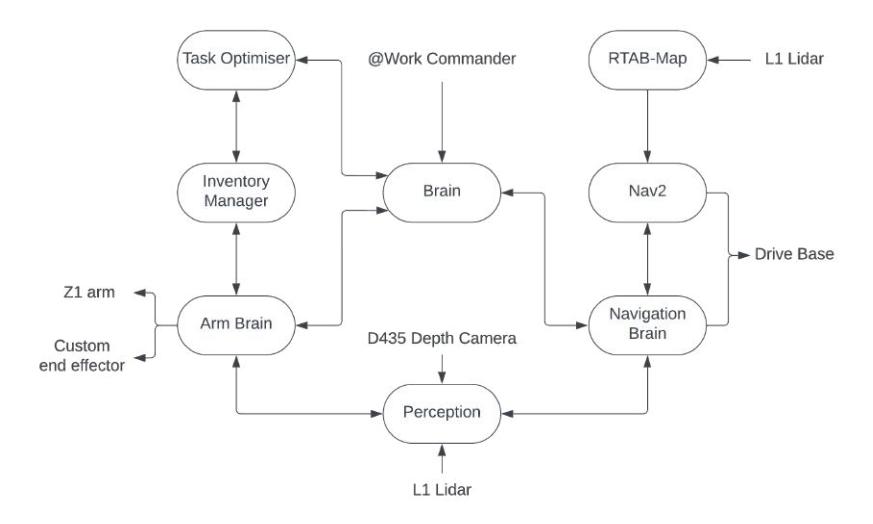
The software architecture displayed in Figure 2, details a high level system overview. Factors considered when designing the architecture included, generalisation, ability to expand, and independent development. Nodes primilarly communiate through custom service calls, with request and success IDs globally shared.
4.2 Navigation
RTAB-Map
To create a map of the environment and localise the robot from a range of data and odometry, Real-Time Appearance-Based Mapping (RTAB-Map) was used. RTAB-Map is a graph-based SLAM approach based on an incremental appearance-based loop closure detector [8]. For integration with ROS2, the rtabmap ros library is specifically used [4]. RTAB-Map was selected over other SLAM approaches due to support and integration of a wide range of sensor types, allowing inputs of the RGBD, LIDAR and IMU data simultaneously [7]. RTAB-Map also allows maps to be saved and reused for pure localisation, as well as a range of parameters for performance adjustment [4].
The current configuration of RTAB-Map used within the robot takes in Point-Cloud2 data from the L1 LIDAR, along with odometry data produced by the drive base's onboard IMU and wheel encoders. This combined data is then filtered and processed to publish a 2D map usable with the Nav2 library discussed below. While currently, results produced by RTAB-Map have proven sufficient for the Robocup@Work environment, even greater accuracy may be possible with the inclusion of depth camera data. Furthermore, it is expected that faster runtime performance of RTAB-Map will be achieved as the team refines parameters and PointCloud data filtering.
Nav2
In addressing the diverse navigation challenges presented by the RoboCup @Work competition, our team has employed the ROS 2 navigation stack Nav2 [9] as the navigation backbone. While Nav2 excels in facilitating general navigation, it lacks specific functionalities critical to our objectives. The stack's limitations, particularly its inability to align precisely with workbenches and to facilitate exact lateral movements for optimal robot positioning during pick and place tasks, prompted us to augment it with custom-developed nodes. A central "Navigation Brain" node orchestrates these components, managing requests from and coordination between the robot's brain node and its arm counterpart. This architecture enables a layered approach to navigation: initially, Nav2 guides the robot to the approximate location of a target workbench based on its coordinates on the map. Upon reaching this vicinity, our custom "Navigation Align" node precisely aligns the robot with the workbench, allowing for accurate execution of pick-and-place operations.
In our development, we've prototyped our alignment node to ensure its efficacy across different workbench heights by utilizing multimodal sensor data. Through the L1 LiDAR point cloud for standard-height workbenches and depth camera-based colour thresholding for zero-height counterparts, we apply linear regression analysis to achieve an accurate relative estimate of the front of the workbench. This methodology allows for accurate calculation of the robot's angle offset and perpendicular distance to the workbench, facilitating precise alignment. Furthermore, our navigation system implements a "jogging" feature that allows for lateral adjustments along the workbench by the arm brain when objects are out of reach. This ensures optimal alignment and distance are maintained without requiring direct navigational control by the arm brain.
4.3 Object Manipulation
Perception Process
An Intel RealSense D435 depth camera attached to the end effector is used to classify and position the target item relative to the robot. When identifying an object, the incoming frame is processed with a custom YoloV8 model trained on a custom RoboCup @Work item dataset. If the item is detected with a high enough confidence, a segmentation mask is produced. Using the centroid and mask rotation, the pose of the item is found and broadcast relative to the robot.
The same process is used for finding a placement location, The segmentation masks produced from the YoloV8 model are merged and then analysed to determine a suitable placement location. For the precision placement tasks, contour matching is used in place of a deep learning model, with the pose estimation derived from the points around the contour. In the case of the rotating workbench, the target item's pose is tracked over multiple frames until a reasonable circular trajectory equation is achieved. This is then analysed to calculate the pickup location and the associated transformation frames are broadcast. Finally, the perception node signals the arm when the item is in the frame.
Object Detection
To support the perception system a YoloV8 model was trained using a custom set of manually classified images [5]. In the process of developing this model, the quality of the dataset greatly improved as the requirements of an effective dataset became better understood. Ultimately the diversity of lighting, angle of photography, backgrounds and number of objects were prioritised to ensure the training set was effective. The volume of the dataset was significantly enhanced by employing extensive image augmentation techniques including but not limited to rotation, flipping, scaling and brightness adjustment.
To improve the efficiency with which new images could be classified and approved, an image processing pipeline was developed. This pipeline consists of several scripts which streamline the model training process. Specifically, scripts were developed allowing a user to quickly and easily mark a point on the object, automatically mask training images using Meta's Segment Anything Model (SAM) [6] and efficiently review masked images for addition to the training dataset. Moving forward, the YoloV8 model may have difficulty identifying objects with similar appearances and varying dimensions. To handle these cases, point cloud analysis will supplement the YoloV8 model.
Arm Brain and Control
The arm brain node receives a message from the brain with the associated task and item code. Based on the command, a set of pre-programmed functions are executed in succession. The functions are generalised to accommodate multiple use cases, such as a generic sweep function which is used for both item identification and virtual wall detection. In the case of arm movement commands, a generic function looks up the transformation to the target location relative to the arm, before passing the desired location to the arm SDK. On-robot transformation frames such as the inventory, home, and sweep positions are statically broadcasted, with external transformation frames broadcasted by the perception node. This approach allows for easy modification and system expansion.
Additionally, the arm brain employs checks to ensure desired results. These include checking that the item has been picked up, and arm movements are valid. In the case where a condition is not met, procedures are in place to perform additional attempts. In the case where a task is continuously unsuccessful or can not be achieved, an unsuccessful message is sent back to the brain and the system moves to the next task.
4.4 Task Planning and Commanding
Task Planning
Before subsystems of the robot can begin receiving tasks, the task message given by the @work commander needs to be processed into a list of instructions. In addition to compiling a set of directions, this sequence must be optimised for the most efficient gathering and distribution of items. To achieve this, the Task Planning node will create a graph from previous map data and the known workstation locations, with an estimated travel cost between each workstation. The Planning node will take in the @work commander task message containing the world's current and desired states. Using this message, the graph will be populated with each item's current and desired location. The developed graph of the competition layout can then be used for calculating the robot's route to complete all tasks.
For the calculation of the robot route, Google's OR-Tools library will be used. OR-Tools is an open-source software suite for constrained and optimization problem-solving [2]. Critical for the challenge of the @Work competition, OR-Tools provides the ability to find solutions for constrained vehicle routing [2]. This allows for a routing solution that considers both the distances between workstations, as well as the 3-item limitation on the robot for competition. Following the route calculation from OR-Tools, the route is then processed by the Planning node into a command list, which is sent to the Task Commanding node for execution.
Task Commanding
Upon receiving a valid command list from the Task Planning node, the Task Commanding node will then begin sending each instruction within this list to the relevant subsystem in a semi-sequential manner. The robot has two primary states, moving and object manipulation, which correspond to the two main subsystems of the drive base and arm. To send each instruction, the commanding node uses a ROS2 client to send an instruction request to a subsystem service. The subsystem will then return a response indicating if the instruction can be executed or if the subsystem is busy. If the subsystem is busy, the commanding node stores the instruction to be resent after a delay.
Following the subsystem response to an instruction, the commanding node will look at the next instruction in the command list, rather than wait for the current instruction to be complete. If the next instruction involves a subsystem not in use, with a task that does not disrupt the current actions of the robot, the next instruction will also be sent. An example of this is the Task Commanding node sending a move command to the drive base, and while the robot is moving, a command is sent to the arm to retrieve an item from inventory. While more complex than sending instructions sequentially, this method also saves a significant amount of time, as the arm is moved into position before arriving at workstations.
Upon a subsystem finishing the execution of an instruction, the subsystem will then send a ROS2 service request to the Task Commanding node. This request will contain information as to if the instruction was completed or if there was a failure. If successful, the Task Commanding node will indicate the subsystem state as ready for a new instruction. If a failure is returned, the Task Commanding node may resend the instruction or modify the command list depending on the failure.
5 Re-usability of the system or parts thereof
Approaching this challenge with no existing codebase, our team has emphasized a modular and expandable system architecture, aiming to facilitate the incorporation of future design enhancements. This can be seen in our use of separate perception, navigation, arm, and brain nodes which communicate through generalised service messages. The robot's tasks - such as the navigation to a workbench, precision placement, and rotating table picking - are defined centrally with specific implementations in respective nodes. Each node implements its respective tasks with a set of fundamental functionalities - such as moving to a specific transformation frame or adjusting relative to the workstation - which can then be structured to accommodate adaptable approaches. Although this modular design approach has extended the initial development phase, the anticipated benefits in terms of system flexibility and future adaptability are deemed to justify the investment.
6 Usage of components developed by other RoboCup @work Teams
When starting to design our approach we researched other teams description papers. The main aspects we took away were the approaches to node architecture, inventory management systems, and perception techniques including the use of onboard sensors and placement. Our system does not use any components developed by other RoboCup @Work Teams. This is mainly due to our usage of ROS2 requiring the development and implementation of new approaches. Additionally, our robotic platform is unique to our team as far as we know, limiting our ability to build off the well-researched KUKA youbot implementation.
Teams such as b-it-bots have started developing a ROS2 solution, with their code publically available however these do not appear to be completed public solutions as of yet [10]. At the end of this competition, we will publicly release our ROS2 code base for other teams intending to use ROS2 to build from.
7 Future Work
While good progress has been made in the short development time so far, There are still many tasks to be completed. Initially work will go into building the smaller robot frame, and remaining field elements. Simultaneously work will be conducted on a secondary platform to develop workstation alignment techniques and improve the efficiency of the task optimiser. Further development includes specialised tasks such as handling virtual walls, rotating tables, and shelves. These tasks will be achieved independently and iterated weekly to ensure reliability.
Our current work schedule places us on track to be able to complete the various challenges laid out in RoboCup @work by the end of May 2024. We then intend to spend the remaining time, fine-tuning, and testing to ensure reliability in a competition environment.
8 Conclusion
UNSW@Work is a new team determined to be competitive at RoboCup @Work 2024. Development has been promising with majority of the tasks required by the Basic Manipulation Test complete. These include, task optimisation, robot localisation, navigation, item identification and collection. The system architecture has been designed in such a way that tasks are easy to modify and expand on. These design decisions allow UNSW@Work to target completion of the rules laid out in the @Work 2023 Rulebook, while also being dynamic to accommodate rule changes.
9 Acknowledgement
We would like to thank RoboWorks and Wayne Liu who has supported the team by supplying the robot platform and equipment used for development. Thanks to Claude Sammut from the University of New South Wales for providing space and advice during development.
References
- Franceschetti, A., Tosello, E., Castaman, N., Ghidoni, S.: Robotic arm control and task training through deep reinforcement learning (2020)
- Google: Google ortools, https://developers.google.com/optimization
- Intel: Depth camera d435, https://www.intelrealsense.com/depth-camera-d435/
- introlab: rtabmapros, https : //github.com/introlab/rtabmapros
- Jocher, G., Chaurasia, A., Qiu, J.: Ultralytics YOLO (Jan 2023), https://github.com/ultralytics/ultralytics
- Kirillov, A., Mintun, E., Ravi, N., Mao, H., Rolland, C., Gustafson, L., Xiao, T., Whitehead, S., Berg, A.C., Lo, W.Y., Doll´ar, P., Girshick, R.: Segment anything. arXiv:2304.02643 (2023)
- Labb´e, M., Michaud, F.: Rtab-map as an open-source lidar and visual simultaneous localization and mapping library for large-scale and long-term online operation. Journal of field robotics 36(2), 416–446 (2019)
- Labb´e, M.: Rtab-map, https://introlab.github.io/rtabmap/
- Macenski, S., Martín, F., White, R., Ginés Clavero, J.: The marathon 2: A navigation system. In: 2020 IEEE/RSJ International Conference on Intelligent Robots and Systems (IROS) (2020), https://github.com/ros-planning/navigation2
- Patel, K., Kalagaturu, V., Mannava, V., Selvaraju, R., Shinde, S., Bakaraniya, D., Nair, D., Wasil, M., Thoduka, S., Awaad, I., Schneider, S., Hochgeschwender, N., Plöger, P.G.: b-it-bots robocup@work team description paper 2023 (2023)
- Robotic, U.: Unitree 4d lidar l1, https://m.unitree.com/LiDAR/
- Robotics, U.: unilidarsdk, https : //github.com/unitreerobotics/unilidarsdk/tree/main
- Roboworks: Mecabot pro, https://www.roboworks.net/store/p/mecabotpro