b-it-bots RoboCup@Work Team Description Paper 2024
Kevin Patel, Vamsi Kalagaturu, Vivek Mannava, Ravisankar Selvaraju, Shubham Shinde, Gokul Chenchani, Chaitanya Gumudala, Harley Lara, Anudeep Sajja, Akhilan Ashokan, Mohammad Wasil, Iman Awaad, Sebastian Houben, Teena Hassan, Paul G. Plöger
Hochschule Bonn-Rhein-Sieg Department of Computer Science Grantham-Allee 20, 53757 Sankt Augustin, Germany
https://www.h-brs.de/en/a2s/b-it-botswork
Abstract This paper presents the b-it-bots RoboCup@Work team and its current hardware and functional architecture for the KUKA youBot robot. We describe the underlying software framework and the developed capabilities required for operating in industrial environments including features such as reliable and precise navigation, exible manipulation, robust object recognition and task planning. New developments include an approach to grasp vertical objects, placement of objects by considering the empty space on a workstation.
Introduction
The b-it-bots RoboCup@Work team at the Hochschule Bonn-Rhein-Sieg (H-BRS) was established in the beginning of 2012. Participation in various international competitions has resulted in several podium positions, including first place at the world championship RoboCup 2019 in Sydney and RoboCup 2023 in Bordeaux[1]. The team consists of Master of Science in Autonomous Systems students, who are advised by research staff and professors. The results of several research and development (R&D) as well as Master's thesis projects have been integrated into a highly-functional robot control software system. Our main research interests include mobile manipulation in industrial settings, omni-directional navigation in unconstrained environments, environment modeling and robot perception in general.
Robot Platform
The KUKA youBot [1] is the applied robot platform of our RoboCup@Work team (see Figure 1). It is equipped with a 5-DoF KUKA manipulator, a two finger gripper and an omni-directional platform. The standard internal computer of the youBot has been replaced by an Intel NUC with an Intel Core i7 processor. In the front and the back of the platform, two Hokuyo URG-04LX laser range finders are mounted to support robust localization, navigation and precise placement of the omnidirectional base. Each laser scanner is configured with an opening angle of 190° to reduce the blind spot area to the left and right of the robot.
Over the years, we have experimented with different sensors and sensor configurations for perception-related tasks, including placing an RGB-D or RGB camera on the end-effector, or mounting a fixed RGB-D camera at a height above the arm. Our current configuration is seen in Figure 1, which consists of a tower-mounted Intel Realsense D435 RGB-D camera, with the tower profile mounted to the metal base plate of the robot. Additionally, we may also mount a second camera (of the same model) between the gripper fingers. The different configurations represent a trade-off between getting a full view of the workspace during perception and better close-up views of the objects during manipulation. But in general, this sensor information is used for vital perception tasks such as 3D scene segmentation, object detection and recognition and barrier tape detection.
The youBot gripper has undergone further customization, where it now features flexible fingers actuated by Dynamixel AX-12 servo motors. These motors offer both position control and force-feedback information, and are controlled by a OpenRB-150 controller which is shown in Figure 2. We currently use a 26 V lithium-ion (Li-ion) e-bike battery[2] to power the youBot.
All technical drawings to the previously described modifications, as well as various 3D printed sensor mounts for the laser scanner and the RGB-D camera etc., have been made public [4].
![b-it-bots robot configuration based on the KUKA youBot [2]](/tdps/industrial_atwork__2024__b-it-bots/_page_1_Figure_1.jpeg)
![Flexible-finger gripper and OpenRB-150 controller [3]](/tdps/industrial_atwork__2024__b-it-bots/_page_2_Picture_1.jpeg)
Robot Software Framework
The software framework of the system is based on ROS (Robot Operating System) [5]. Information is passed between functional components through ROS communication channels, specifically using topics. The use of topics allows for non-blocking communication and the ability to monitor communication between nodes at any time. The broad range of tools offered by ROS are employed for visualizing, testing, and debugging the entire system. Our development approach emphasizes the creation of small, lightweight, and modular components that can be repurposed in different processing pipelines, including those in different domains or on alternative robot platforms, such as the Care-O-bot 3 [6]. We have also standardized our nodes with the addition of event in and event out topics. Our components listen to the event in topic which expects simple command messages and allow for: starting, stopping or triggering (run once) of nodes. The components provide feedback of their status on the event out topic when they finish. This allows us to coordinate and control the components with either simpler state machines or task planning; in either case, the control flow and data flow between the components remains separated. This also allows us turn off computationally expensive nodes when they are not needed.
We have begun porting our software to ROS2 [7], since the last version of ROS1 will reach its end-of-life by 2025. Most of our code is open source at [8].
Navigation
Several components have been developed and integrated to move the robot from one place to another in cluttered and even narrow environments.
Map-based Navigation
The navigation components we use are based on the ROS navigation stack move_base which uses an occupancy map together with a global and local path planner. For the local path planner a Dynamic-Window-Approach (DWA) is deployed which plans and executes omni-directional movements for the robot's base. This enhances the maneuverability, especially in narrow environments.
The vast amount of configuration parameters of the move_base component have been fine-tuned through experiments with several and differently structured environments in simulation (e.g. a corridor, narrow passages, maze, etc.).
Perception
Several components have been developed for processing the image and point cloud data from the tower-mounted camera.
![Object perception pipeline [2]](/tdps/industrial_atwork__2024__b-it-bots/_page_3_Figure_8.jpeg)
Object Recognition
Perception of objects relevant for industrial environments is particularly challenging. The objects are typically small and often made of reflective materials such as metal. We use an RGB-D camera which provides both RGB and depth images of the environment. The perception pipeline is outlined in Figure 3.
In our approach, we first employ 2D image-based detection and then a 3D point cloud to estimate the object's pose. For object detection, we employ YOLOv8 [9], a single-stage deep learning-based detector. It predicts both the axis-aligned bounding boxes and the class probabilities for each bounding box. The training set consists of about 1500 annotated images on various backgrounds, with an average of 300 occurrences of each object, with the exception of a few object pairings that are similar in color and texture but only differ in size, for which we gathered 500 instances each. We use the Segment Anything Model (SAM) [10] to semi-automatically annotate bounding boxes, reducing annotation effort and time. We utilize YOLOv8's [9] small model with 10M parameters, which can run at 10 FPS on CPU. The dataset is publicly available on Zenodo[3].
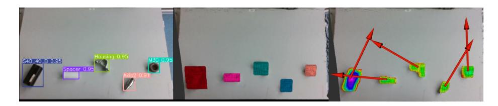
To generate a grasping position for a detected item, we first extract the 3D points from the point cloud associated with each pixel in the 2D bounding box. To calculate the workstation height, the dominating horizontal plane is segmented using random sample consensus (RANSAC). After applying a passthrough filter to the object cluster based on workstation height, we utilize the filtered cluster's centroid as the grasping position. For yaw, we use Principal Component Analysis (PCA) on the cluster to align the gripper with the principal axis. We assume a horizontal workstation surface, thus roll and pitch are set to zero. Figure 4 depicts the full process, from object detection to pose generation (left to right).
Cavity Recognition
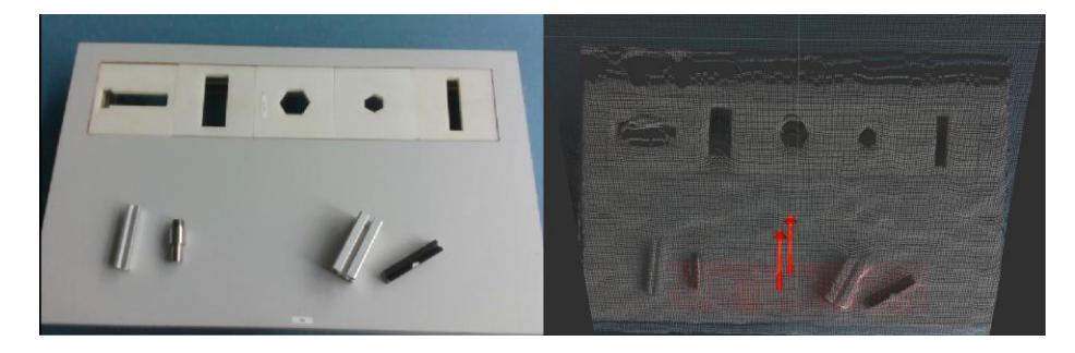
For precision placement of objects into cavities in Advanced Transportation Task 1, the perception pipeline in Fig. 3 is used with a task configuration parameter that selects a different YOLOv8 model trained on the cavities, as shown in Fig. 5. To extract 3D cavity clusters for the pose, only points below the workstation are considered, as they are points from the floor below in the shape of the cavities. These points are first projected back into the workstation plane, then their pose is computed using the same approach as object clusters.

Rotating Table
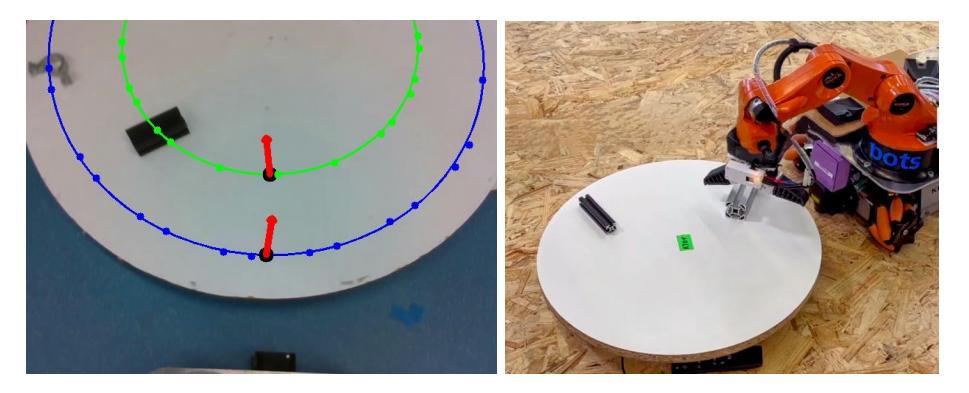
For grasping from the rotating table, we first perform object detection using YOLOv8 on a 15-frame sequence from the camera. Centroids and orientations of the target object are translated to the robot's base frame for all images and saved with their timestamps. A circular model is fit to the series of centroids (see Fig. 6) to predict the direction and rotation speed of the table.
The point on the circle that is closest to the robot is chosen as the grasp position (see Fig. 6), and the predicted time when the object will reach the selected location is determined by taking into account the last known position of the object and the rotation speed of the table.
Object Manipulation
Several components have been designed and integrated into the robot to provide reliable object grasping.
MoveIt![4] has lower joint velocities than the youBot driver's position command interface without substantial adjustment. To accelerate arm motions, we moved to the position command interface for motions from and to fixed pre-defined locations in which safety is ensured, such as moving to object staging platforms. We continue to utilize MoveIt! for trajectory planning while moving to variable positions, such as grasping an object.
For grasping, the robot approaches the object from above, with the end-effector perpendicular to the workstation. However, this reduces the arm's workspace, leading to inverse kinematics (IK) failures for objects further away from the robot. In the event of an IK failure with the default methodology, we implement an orientation-independent strategy that samples poses from several angles such that the arm may reach the object. While this strategy expands the robot's workspace and enhances grasping success rates, it is also prone to failure when approaching objects at an angle that is too horizontal. When grasping from a workstation with an overhanging shelf, the standard top-down technique is dangerous due to the risk of colliding with the shelf, particularly during the approach and retract phases. As a result, base motions are employed to align the robot with the object while maintaining a safe, pre-grasp pose for the arm. After grasping, base motions are utilized to move away from the workstation.
To carry out grasp verification, we depend on the feedback from the gripper controller, which continuously emits the current state of the gripper, which can be open, closed, grasped, or moving. These states are calculated using the gripper's completely open and fully closed motor angles, as well as the current operation being performed. The controller calculates the relative difference between the motor locations for each finger to determine the gripper's present state. While this works effectively for larger items, the relative difference is insufficient for thin objects to provide accurate grip verification.
Free Space Detection
To place an object, the robot first searches the workstation for empty spaces based on 3D point cloud data from the RGB-D camera. RANSAC is used to segment the dominating horizontal plane, and any plane inliers that fall inside the manipulation zone are considered candidate free points. Random candidates are chosen, and if the number of neighboring free points within a certain radius falls below a particular threshold, they are rejected. The approach is repeated until at least two candidates with enough free neighbors have been identified.
Task Planning
Many robot application, especially in competitions, have been developed using finite-state machines (FSM). But even for apparently simple tasks, such a FSM can be very complex and thus become easily confusing for humans. Therefore, our current FSMs have been replaced with a task planner.
We test using both the Mercury 2014 planner [11] and the LAMA planner [12]. The LAMA planner is built on the Fast Downward planning system and uses PDDL. As such, it uses similar interfaces to those of the Mercury planner. The planners allow specifying various cost information. In terms of RoboCup@Work, these costs and can be, for example, distances between locations or probabilities of how good a particular object can be perceived or grasped.
Small and clear state machines covering basic actions, like move-to-location, perceive-object, grasp-object or place-object are used as actions for the planner. For a particular task, the planner then generates a sequence of those actions in order to achieve the overall goal. Finally, this plan is being executed and monitored. In case of a failure during one of the actions, re-planning is being triggered and a new plan is generated based on the current information available in the knowledge base.
Conclusion
We presented several modifications applied to the standard youBot hardware configuration as well as the functional core components of our current software architecture. Besides the development of new functionality, we also focus on developing components in such a manner that they are robot independent and can be reused for a wide range of other robots with even a different hardware configuration. We applied the component-oriented development approach defined in BRICS [13] for creating our software which resulted in high feasibility when several heterogeneous components are composed into a complete system.
Acknowledgement
We acknowledge the financial support of the Vice President of International Affairs and Diversity at Hochschule Bonn-Rhein-Sieg (H-BRS), the Computer Science department at H-BRS, the Student Committee (AStA) at H-BRS and the b-it Bonn-Aachen International Center for Information Technology.
References
- KUKA youBot. http://www.youbot-store.com/developers. (Online: 01.03.2024.).
- Gokul Chenchani, Kevin Patel, Ravisankar Selvaraju, Shubham Shinde, Vamsi Kalagaturu, Vivek Mannava, Deebul Nair, Iman Awaad, Mohammad Wasil, Thoduka Santosh, Sven Schneider, Nico Hochgeschwender, and Paul G. Plöger. bit-bots: Winners of RoboCup@Work 2023. In Proceedings of the 26th RoboCup International Symposium, Bordeaux, France, 2024.
- Teensy 4.0 Development Board. https://www.pjrc.com/store/teensy40.html. (Online: 01.03.2024.).
- Technical drawings of BRSU youBot modifications. https://github.com/b-it-bots/technical_drawings. (Online: 01.03.2024.).
- Morgan Quigley, Ken Conley, Brian P. Gerkey, Josh Faust, Tully Foote, Jeremy Leibs, Rob Wheeler, and Andrew Y. Ng. Ros: an open-source robot operating system. In ICRA Workshop on Open Source Software, 2009.
- U. Reiser, C. Connette, J. Fischer, J. Kubacki, A. Bubeck, F. Weisshardt, T. Jacobs, C. Parlitz, M. Hagele, and A. Verl. Care-o-bot 3 - creating a product vision for service robot applications by integrating design and technology. In IEEE/RSJ International Conference on Intelligent Robots and Systems (IROS), pages 1992 1998, Oct 2009.
- Steven Macenski, Tully Foote, Brian Gerkey, Chris Lalancette, and William Woodall. Robot operating system 2: Design, architecture, and uses in the wild. Science Robotics, 7(66):eabm6074, 2022.
- Software repository of the b-it-bots team. https://github.com/b-it-bots/mas_industrial_robotics. (Online: 01.03.2024.).
- Glenn Jocher, Ayush Chaurasia, and Jing Qiu. Ultralytics YOLOv8. https://github.com/ultralytics/ultralytics, 2023. (Last Accessed: 01.03.2024).
- Alexander Kirillov, Eric Mintun, Nikhila Ravi, Hanzi Mao, Chloe Rolland, Laura Gustafson, Tete Xiao, Spencer Whitehead, Alexander C. Berg, Wan-Yen Lo, Piotr Dollár, and Ross Girshick. Segment Anything. arXiv:2304.02643, 2023.
- Michael Katz and Joerg Hoffman. Mercury planner: Pushing the limits of partial delete relaxation. IPC 2014 planner abstracts, pages 4347, 2014.
- Silvia Richter, Matthias Westphal, and Malte Helmert. Lama 2008 and 2011. In International Planning Competition, pages 117124, 2011.
- R. Bischoff, T. Guhl, E. Prassler, W. Nowak, G. Kraetzschmar, H. Bruyninckx, P. Soetens, M. Haegele, A. Pott, P. Breedveld, J. Broenink, D. Brugali, and N. Tomatis. Brics - best practice in robotics. In In Proceedings of the IFR International Symposium on Robotics (ISR 2010), Munich, Germany., June 2010.