RoboCupRescue 2009 - Robot League Team AVA (Malaysia)
Sharifah Azizah Sayeed A. Ghazali
AVA STRATEGIC ALLIANCE 23-3rd, Jalan 5/109F, Plaza Danau 2, Taman Danau Desa 58100 Kuala Lumpur, Malaysia
Abstract This document introduces AVA rescue robot team and its work in developing functional rescue robots. Our main effort has been focused on efficient Human Robot Interaction (HRI) for a dynamically complex system and a Graphical User Interface (GUI) supporting adjustable autonomy. We implement the system on two identical tracked robotic platforms which are equipped with a range of state of the art sensors for autonomous navigation and victim detection.
Introduction
Research and Development (R&D) team at AVA Strategic Alliance Company works on a Human Machine Interaction (HMI) project using Virtual Reality (VR) systems to increase efficiency of training courses of personals in various required fields. To examine efficiency of our HMI system, we have decided to participate at RoboCup rescue robot field where teams are supposed to find victims as a target in a complex environment.
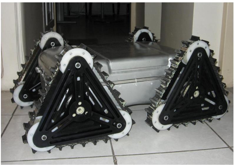
Our system is implemented on two identical high mobility tracked robotic platforms (Fig. 1) [1] which benefit state of the art sensors for autonomous navigation and victim detection. These robots use a complicated skid steering called Triangular Tracked Wheel (TTW) locomotion mechanism [2] which makes it possible to navigate in rough terrains like collapsed buildings.
Besides developing a friendly video centric User Interface (UI) we are working on adjustable autonomy [3] to reduce complexity of still complex multi robot controlling.
1. Team Members and Their Contributions
• Sharifah Azizah Sayeed A. Ghazali Team leader • AVA R&D team Software
• Jimmy Lim Jit Whang Logistical support
• Tan Sri Mohd Jamil Johari Advisor
With our special thanks to Takin Robotics Company and their engineering team for technically supporting us.
2. Operator Station Set-up and Break-Down (10 minutes)
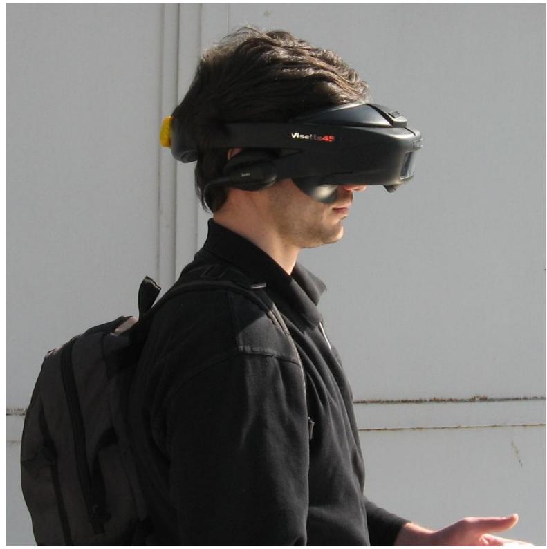
Our robots are controlled by a lightweight rugged industrial computer using a game pad and a Head Mounted Display (HMD) (Fig. 2). All these equipments are included in a waterproof backpack and operator can easily transport it to the control station. The industrial computer used in the OCU is vibration resistive and the HMD has a transparent display therefore, operator can control robots even while he/she is running. Prior to each mission robots will be booted up to be transported to the arena by two team members (operator can also be one of these two people). As soon as they placed the robots in start point, operator can start control application to drive the robots. At the end of each mission, operator will deliver mission data while two other team members will take the robots out of the arena. This will be done in less than 5 minutes.
3. Communications
Each robot utilizes a 5 GHz IEEE802.11a Access Point/Bridge with a pair of external antennas to exchange data (e.g. high level control commands, sensor data and digital audio/video) with another one on OCU.
We use channel 44 as our default setting (Table 1) but it can easily be changed to any possible channel if it is needed.
Table 1. Used communication frequencies
| Rescue Robot League | ||||||
|---|---|---|---|---|---|---|
| AVA (MALAYSIA) | ||||||
| Frequency | Channel/Band | Power (mW) | ||||
| 5.0 GHz - 802.11a | selectable | 100 |
4. Control Method and Human-Robot Interface
As mentioned, we are implementing an adjustable autonomy approach to reduce complexity of multi robot controlling. Using this method, operator may enter to the robot control loop when it is needed. The available autonomy modes are:
- Teleoperation: no sensors are used to help keep the robot from bumping into objects
- Safe: teleoperation with obstacle avoidance provided by the system
- Shared: semi-autonomous navigation with obstacle avoidance where the user communicates his desires at points in the route where a choice must be made or can otherwise bias the robot's travel direction
- Follow: robot follows its moving leader and avoids collision
- Full autonomous: robot chooses a goal point (based on Frontier Exploration algorithm [4]) to which it then safely navigates
We will surely limit this capability to full autonomous mode for the robot exploring in yellow arena.
Although providing several autonomy options facilitates operator's task in HRI loop but, most operators don't take enough care to suggestions from this system [5]. To overcome this problem, we are implementing an autonomy mode suggestion system [6] in our GUI which is displayed on HMD.
Though using HMD to control rescue robots efficiently is not new to RoboCup rescue robot league [7] but our GUI benefits of special see throw capability of our high resolution HMD.
Furthermore, operator is alerted about critical situation via stereo headphone of the HMD and vibrating joystick.
5. Map generation/printing
Teams are proposed to represent a 2D map using occupancy grids in addition to information about victim locations. Our map generation module is based on recently well known GMapping software [8] which uses Grid-based SLAM algorithm with Rao-Blackwellized Particle Filters by Adaptive Proposals and Selective Resampling [9]. Practical experiments prove the robustness of this algorithm in USAR applications [10]. All we have done is just tuning parameters of this algorithm to have an optimum result with our hard/software architecture.
6. Sensors for 5avigation and Localization
Our robots use Player framework [11] as control infrastructure which utilizes a TCP socket-based client/server model.
A built in Player module transfers IMU corrected encoder readings to the robot position vector (x, y, θ) which still is additively error prone and it is used only for a rough estimation about the robot location and orientation.
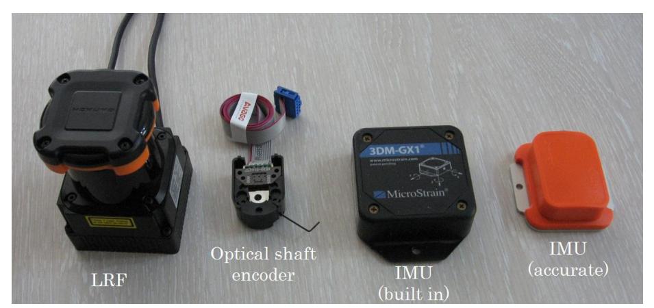
Each robot has a Hokoyo UTM-30 LX scanning Laser Range Finder (LRF). This long range (up to 30 m), wide angle (270°) and fast (25msec/scan) LRF helps us to drive the robot at a high speeds while mapping. Our experience shows that the pose vector can be completely neglected without worry about SLAM output using this LRF.
Also it should be noted that we use active sensing method [12] to mechanically stabilize LRF using outputs of IMU. We found in our practical experiences that built in IMUs of our robots are not fast enough and we use another fast IMU to remain LRF horizontal.
In addition to these sensors, our robots have a pair of cameras to provide fine images of robot surroundings and its own status. One of these cameras has optical zoom capability and it is mounted on a pan/tilting servo mechanism. This camera is controlled by operator's head orientation using built in Head Tracker of our HMD. Fig. 3 illustrates the navigation sensors used in our robots.
7. Sensors for Victim Identification
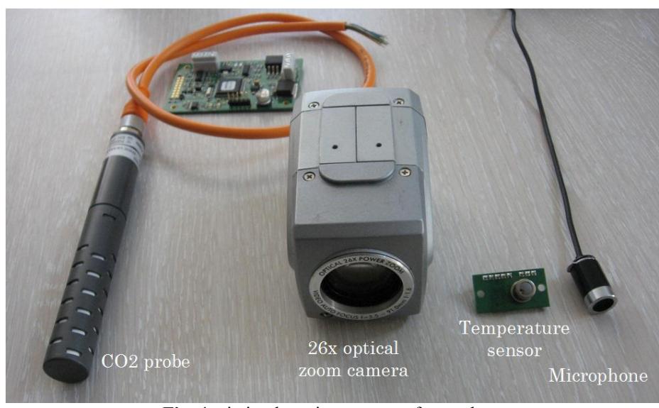
Autonomous victim detection is mainly based on temperature sensor data. Four 8 pixel temperature sensors mounted on a precise servo are used to scan environment in 180 deg. field of view at 1 Hz for heat sources having 37±2 degrees Celsius. When such a heat source is detected, the control system informs operator and drives the robot autonomously into its direction and stops approximately 0.5 meter in front of the heat source if it is in full autonomous mode.
Although our robots are equipped with cameras, we don't use them for skin color based victim detection. Victim detection using skin color is not computationally efficient solution in RoboCup rescue arena due to the color of arena [13].
In addition to temperature sensors, we use one CO2 sensor and a sensitive microphone on each robot to be aware of nearing to victim zones. Fig. 4 shows these sensors.
8. Robot Locomotion
As mentioned before, we use a tank like tracked robotic platform which specially designed to operate in unstructured environments. It has an extraordinary Four-Tracked drivetrain layout which is called TTW.
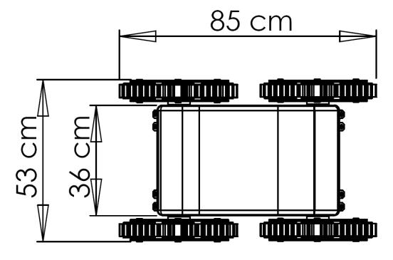
The front-left and rear-left tracks (or the front-right and rear-right tracks) have a common powertrain which their velocity is controlled by an accurate motor controller. Thus, both tracks at each side move in the same velocity and provide skid steering capability. In addition to tracks, the robot can move forward or backward by rotating its triangular modules. These modules are position controlled and they can also be used to acquire maximum traction force of tracks by precisely adjusting the orientation of tracks to contact surface. The following table lists mechanical characteristics (Fig.3) of our robots.
Table 2. Mechanical characteristics of our robots
| Feature | QTY |
|---|---|
| Weight | 32 Kg |
| Nominal power | 540 w |
| Max continuous velocity | 1.4 m/s |
| Max discrete velocity | 1.3 m/s |
| Max velocity | 2.7 m/s |
| Max passed gradient | 0.9 (42 deg) |
| Max payload (at max gradient) | 42 Kg |
9. Other Mechanisms
Our robotic platforms use a power management system which supervisory controls all activities inside the robot (e.g. switching devices on/off, voltage - current monitoring and limiting). The power management system is the first and only system that a user can directly turn it on/off. When it turned on, it follows a step by step procedure to turn on and test all necessary devices to be wirelessly connected to the OCU (e.g. Ethernet switch and Access Point). If anything goes wrong it begins blinking an LED and alarming.
After first step of booting up, the power management system directly connects to the OCU and waits for operator's commands. At this time operator is able to boot up onboard Industrial computer. Using this system, operator is able to remotely turn on/off or restart any onboard devices even Industrial computer.
10. Team Training for Operation (Human Factors)
Although we do our best to make our HRI more and more user friendly, but it still needs about one day of familiarization to drive the robots properly. After becoming acquainted with robot controlling, it will be quite similar to game playing.
Also it should be taken into account that not using our HMD is strongly recommended to people suffering from hurt disorders, high blood pressure or eye diseases and who are under 15 years age.
11. Possibility for Practical Application to Real Disaster Site
We don't have any practical experience with real disaster sites yet. Actually we are taking our first steps towards this high goal of rescuing human life.
12. System Cost
The following table lists approximate cost of our system.
Table 3. Price list
| Part 5ame | Company | Type | QTY | Unit Price |
|---|---|---|---|---|
| Robot platform | Takbot | ALPHA | 2 | 35,000 USD |
| LRF | Hokuyo | UTM | 2 | 5,590 USD |
| IMU | Xsens | MTi | 2 | 2,550 USD |
| CO2 sensor | Vaisala | GMM | 2 | 925 USD |
| Temperature sensor | Devantech | TPA81 | 7 | 112 USD |
| Camera | Telecom | 2 | 32 USD | |
| Microphone | 2 | 8 USD | ||
| Industrial computer | Advantech | UNO-2182 | 1 | 2,250 USD |
| Access Point | PLANNET | WDAP-2000PE | 1 | 190 USD |
| Gamepad | Xbox | Xbox 360 | 1 | 48 USD |
| HMD | Cybermind | Visette45ST SXGA + Head Tracker | 1 | 15,200 USD |
| Other Electronics | 700 USD | |||
| Total Price | 107,382 USD |
References
- Takin Robotics Company: http://www.takbot.com/
- A. H. Soltanzadeh, A. Chitsazan.: Mobile Robot locomotion based on Tracked Triangular Wheel mechanism. Final thesis for B.Sc. degree, Mechanical Engineering Department. IAUCTB (2006)
- A. Birk, M. Pfingsthorn.: A HMI supporting Adjustable Autonomy of Rescue Robots. RoboCup 2005, Robot WorldCup IX (2005)
- B. Yamauchi.: A frontier-based approach for autonomous exploration. IEEE International Symposium on Computational Intelligence in Robotics and Automation (1997)
- B. Keyes.: EVOLUTION OF A TELEPRESENCE ROBOT INTERFACE. Final thesis for M.Sc. degree. Department of Computer Science. University of Massachusetts Lowell (2007)
- M. Baker, H. A. Yanco.: Autonomy Mode Suggestions for Improving Human-Robot Interaction. IEEE International Conference on Systems, Man and Cybernetics (2004)
- ORPHEUS robotic system project: http://www.orpheus-project.cz/
- OpenSLAM: http://www.openslam.org/
- G. Grisetti, C. Stachniss, W. Burgard.: Improving grid-based SLAM with raoblackwellized particle filters by adaptive proposals and selective resampling. ICRA05 (2005)
- B. Balaguer, S. Carpin, S. Balakirsky.: Towards Quantitative Comparisons of Robot Algorithms: Experiences with SLAM in Simulation and Real World Systems. IROS workshop (2007)
- Player/Stage: http://playerstage.sourceforge.net
- J. Pellenz. Rescue robot sensor design: An active sensing approach. Fourth International Workshop on Synthetic Simulation and Robotics to Mitigate Earthquake Disaster (2007)
- J. Pellenz.: TDP of resko@UniKoblenz (Germany). RoboCup Rescue Robot League (2008)