RoboCupRescue 2009 - Robot League Team AriAnA (Iran)
Hossein Mahbadi, Amir H. Soltanzadeh, Mahdi Emami, Mehdi Soltanzadeh
Robotics Research Laboratory Azad University of Central Tehran Branch Niayesh Campus, Tehran, 14687 Iran; Xarrin Advanced Technologies 7th Floor, No.1, Southern Shiraz Ave., Tehran, 14369-53958 Iran
http://www.rrl.ir · http://www.xarrin.com
Abstract This paper outlines rescue robots of AriAnA robotics team, the result of our long term research project on high mobility systems. Both robots benefit an innovative locomotion mechanism called Tracked Triangular Wheel which provides the advantages of wheeled, tracked and legged systems together. These robots are equipped with a range of state of the art sensors and hardware. Already our main concern has been making the robots more and more intelligent focusing on reliable navigation, localization and mapping algorithms.
Introduction
AriAnA is the official robotics team of Islamic Azad University of Central Tehran Branch (IAUCTB) and was founded as a basis for a research project on USAR robotics. Our vision is "Aiding human rescue teams in real urban disasters, by providing them intelligent and reliable robotic systems." And our mission is "Building a collaborating team of intelligent search and rescue robots with high mobility."
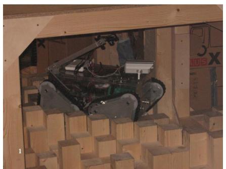
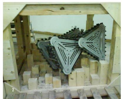
At primitive steps we designed, manufactured and implemented a novel locomotion mechanism that we call Tracked Triangular Wheel (TTW) [1]. We actually reinvented the wheel to achieve better mobility. By utilizing this new locomotion mechanism, our robot can move on a flat ground as fast as a wheeled system, on the stairs as stable as a tracked one and on the step field just like a legged robot. The first prototype, ARIAN was used in RoboCup 2006 Germany competitions.
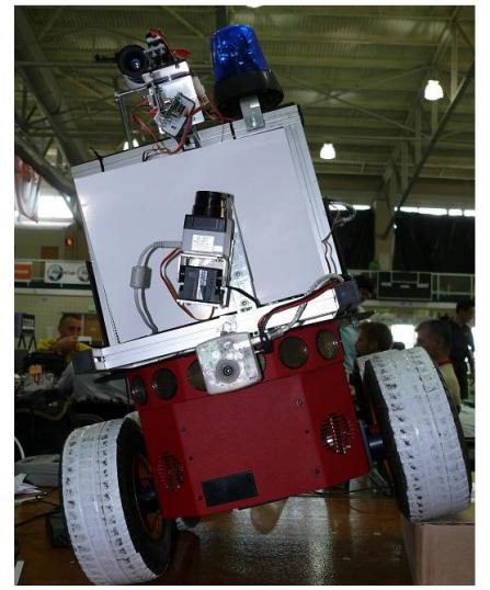
We continued development by modifying ARIAN and constructing a new model called META (Fig.1).
Both robots are Tele-Operated systems and use autonomous modules for Simultaneous Localization And Mapping (SLAM) as well as victim detection.
1. Team Members and Their Contributions
• Dr. Hossein Mahbadi Team leader • Amir Hossein Soltanzadeh Mechanical designer, Manager • Ahmad Chitsazan Mechanical manufacturer • Mahdi Emami Electronics, Hardware • Mehdi Soltanzadeh Software engineer, Operator
With special thanks to:
• Dr. Abdollah Baradaran Advisor • Azad University of Central Tehran Branch Sponsor • Xarrin Advanced Technologies Technical support • T. T. Khoozestan Co. Mechanical manufacturing
2. Operator Station Set-up and Break-Down (10 minutes)
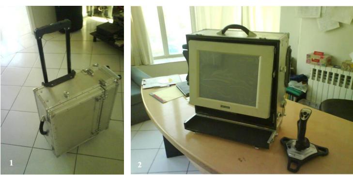
Considering baggage allowance limits of international airlines, we have made a number of portable suitcases for traveling to the competition venue. Following items are included in our travel package:
- Main Unit (QTY=2)
- o Robot main body
- Operator Control Unit (QTY=1)
- o Industrial computer
- o Touch screen LCD monitor
- o Access point
- o Portable printer
- o Joystick
- Equipment Unit (QTY=1)
- o Battery packs and chargers
- o Mechanical instruments
- o Electronics tools
2.1. At RoboCup competitions
After robot setup at first day, we need two people besides the operator for setup and break-down procedures.
2.1.1. Operator Station Set-up (10 minutes)
We use a custom designed Operator Control Unit (OCU) for fast set-up and break-down (Fig.2). While two members carry the robots to the arena, the operator brings the OCU to the operator station. When all systems are switched on, an automatic system check is performed under operator's supervision. The whole station set-up process takes less than 10 minutes, with the most time consuming part being sensor warm up.
2.1.2. Operator Station Break-down (10 minutes)
At the end of each mission, the operator has two specific tasks: stopping the system and delivering generated data in both printed and digital formats while other two members are taking the robots out of the arena. This takes about 5 minutes.
3. Communications
We use an Access Point (AP) which supports 802.11a and 802.11b/g simultaneously; however, our default setting is 5GHz 802.11a CH. 11. In addition to AP we use a remote joystick and a wireless headset (Table 1).
At each mission, both robots keep an eye on network connectivity. When network connectivity is lost for a long period and reconnection attempts fails, the disconnected robot autonomously tries to rollback to a place with network connectivity using its locomotion history. If rollback fails, it begins alarming by sound and flashing light.
Table 1. Used communication frequencies
| Rescue Robot League | AriAnA (IRAN) | ||
|---|---|---|---|
| Frequency | Channel/Band | Power (mW) | |
| 5.0 GHz - 802.11 a | (selectable) | 100 mW | |
| 2.4 GHz - Bluetooth | n/a | 5 mW | |
| 2.4 GHz - Bluetooth | n/a | 2 mW |
4. Control Method and Human-Robot Interface
Our control system consists of the onboard robot control and OCU where most computational tasks are done onboard and the results are transmitted to OCU. We use identical hardware and software control systems on both robots.
4.1. Hardware Overview
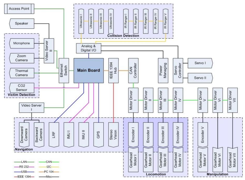
Hardware of our robots (Fig. 3) consists of these main sections:
Main Unit
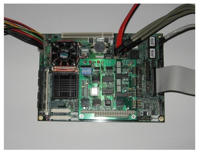
Computational system on mobile devices like robots must be compact, rugged, low power, reliable, extendable and easy to handle. PC/104 is an embedded computer standard controlled by the PC/104 consortium which defines both a form factor and computer bus. PC/104 is intended for specialized embedded computing environments where applications depend on reliable data acquisition despite an often extreme environment. We chose PC/104+ hardware to be employed on both robots (Fig. 4). The main unit consists of a motherboard, CAN controller, FireWire (IEEE 1394) card and Analog/Digital IO. Below is the feature list of the main board:
- o Pentium 2.0 GHz with 2MB cache
- o 2 GB DDR2 RAM, 80 GB SATA2 2.5" Hard Disk
- o 4×RS232, 6×USB, 2×LAN ,8×GPIO
- o PC 104+, Mini PCI, PCI Slot interfaces
- o 204×146 mm, 0.85kg
- o +5V and +12V, Max 30W, Suspend 18W
- o Suitable temperature, humidity and vibration characteristics
PC/104+ type CAN controller and FireWire cards are used to connect motor drivers and stereo vision module to the main board respectively.
Analog/Digital IO board is microcontroller based and is used to collect sensor data from ultrasonic and IR rangers, also to control power management unit and laser range finder stabilizer servos. This board interfaces with motherboard via USB.
Motor Driver
We are using reliable motor drivers which provide accurate position and velocity controlling for simple DC motors. These drivers are connected to motherboard via CAN bus to reduce wiring inside the robots.
Video Server
Two robust video servers are employed in each robot to convert analog videos to MPEG4 format and stream them over LAN.
Power Supply and Management
Results of practical tests indicate that average power consumption of each robot is approximately 300Wh. 12x4000mAh Polymer Li-Ion cells are packed to build a 24V-8000mAh (192Wh) battery pack with capacity to deliver an 1880W high-drain discharge. With this pack robots are expected to handle 40 min. missions.
We have built a power management unit with multiple digitally controlled outputs. Voltage and current of each output can be digitally adjusted. This unit is connected to main board via D/A IO controller which enables the operator to monitor power consumption of individual devices besides remaining battery power.
We are working on direct LAN access to power management unit to switch devices on/off in emergency cases. The other hardware components are discussed in the next sections.
4.2. Software Overview
We use Player/Stage framework for robot control. Sensor reading and ranging based SLAM modules run onboard in robots and GUI also player server run on OCU as our human robot interface.
4.2.1. Player robotic server
Player is a device server that provides a powerful, flexible interface to a variety of sensors and actuators. Because Player uses a TCP socket-based client/server model, robot control programs can be written in any programming language and can execute on any computer with network connectivity to the robot. In addition, Player supports multiple concurrent client connections to devices, creating new possibilities for distributed and collaborative sensing and control [2].
4.2.2. Human-Robot Interface (HRI)
Design of HRI directly affects operator's ability to fulfill a task. It also affects her/his ability to understand the current situations, make decisions and provide high level commands to the robotic system [3].
As a key point in developing an effective, efficient, usable, and deployable interface, we need to appreciate the operator needs and requirements as well as the way of presenting them to her/him [4]. The previous experiences besides observing the GUI of First Person Shooter (FPS) video games were very useful in this regard. In developing our GUI, we've heeded the following concepts [5]:
- o Awareness of the robots surroundings: how accurately the user can describe the robot's local environment
- o Awareness of robots status: knowledge about the state of robot itself, such as its power level, orientation, attitude, or the position of its camera relative to the front of the robot
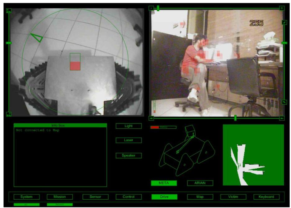
Fig. 5 illustrates our main GUI which is designed for multi-robot control.
We have three cameras installed on robots' arm. Top left image is from downward-looking wide angle camera overlaid by robot heading indicators. Top right image is from PTZ camera overlaid by thermal image. This automatically switches to backward camera, when robot is moving backward. Info box, robot 3d rendering and last updated map of active robot besides remaining battery power are displayed below the camera images. OCU has a touch screen LCD thus operator can open other GUI screens by touching buttons in main screen.
5. Map generation/printing
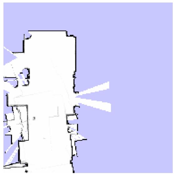
We are using a Rao-Blackwellized Particle Filtering algorithm [6] as a real time FastSLAM [7]. This algorithm uses IMU corrected LRF data as well as odometery for 2D mapping. Entire SLAM algorithm runs on-board individually on each robot and the resulted Occupancy Grid map is transmitted to OCU periodically during the missions (Fig. 6). Operator can edit the map to add elements like victim information or label locations to help human rescuers to identify them. At the time being we don't actually do multi-robot mapping and at the end of each mission the OCU do a post processing to merge the generated map of each robot to prepare final report. Finally a 2D map with user additions is printed.
6. Sensors for Navigation and Localization
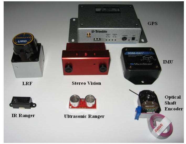
As stated before, both robots are tele-operated with identical hardware components and sensors. Like most tele-operated mobile robots, our main navigation sensor is camera. In addition to the cameras, the robots are equipped with these sensors for navigation and localization (Fig. 7):
- o Laser Range Finder (QTY=1): indoor
- o Optical shaft encoder (QTY=4): indoor/outdoor
- o IMU (QTY=2): indoor/outdoor
- o Stereo Vision module (QTY=1): indoor/outdoor
- o GPS (QTY=1): outdoor
- o Ultrasonic ranger (QTY=4): indoor
- o IR ranger (QTY=5): indoor
Data of these sensors is also used as a basis for critical collision detection and avoidance. If a collision is detected, avoidance gets higher priority than user command. Collision avoidance feature can be turned on/off by operator, so in cases like step fields you can turn off this feature to try your chance.
It should be mentioned that we have developed a servomechanism to electromechanically stabilize LRF using one of two IMUs on each robot similar to the method utilized by team "RESKO" at RoboCup 2007 U.S. (Fig. 8). Additionally, we are working on a Stereo Vision based visual odometery to be replaced with traditional odometery.
7. Sensors for Victim Identification
We have constructed a manipulator to hold all victim detection sensors. These sensors are packed in a pan/tilting end effecter called Victim Detection Package (VDP). The VDP equipped with these sensors are used for victim detection (Fig. 9):
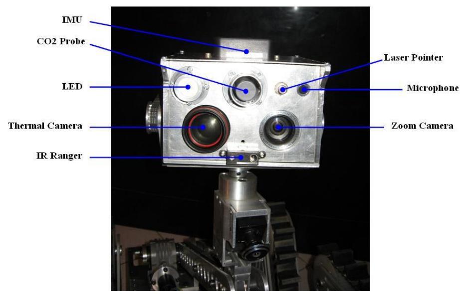
260x zoom camera
This camera provides fine images of environment even in almost absolute darkness.
Thermal Imaging Camera
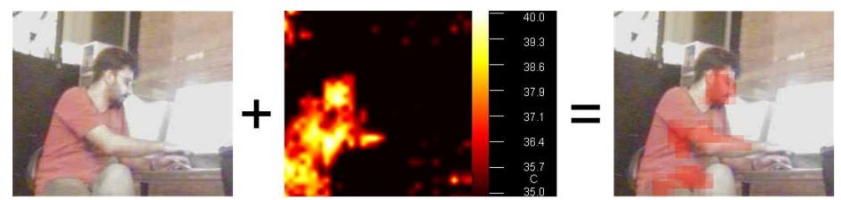
This compact, lightweight and low cost thermal camera is employed to precisely monitor surrounding heat sources. To make its stream more meaningful to the operator, the output is filtered to human body temperature and calibrated with respect to the zoom camera then it is mixed with streams from zoom camera (Fig. 10). This technique was introduced by team "CASualy" at RoboCup 2005 Japan [8].
CO2 Sensor
We've equipped both robots with CO2 sensors to sense the exhaled CO2 from victims. They have a response time of about 20 sec. which is common in most CO2 sensors.
Microphone
A sensitive microphone and small speaker is used to have a bi-directional communication between operator and victim.
8. Robot Locomotion
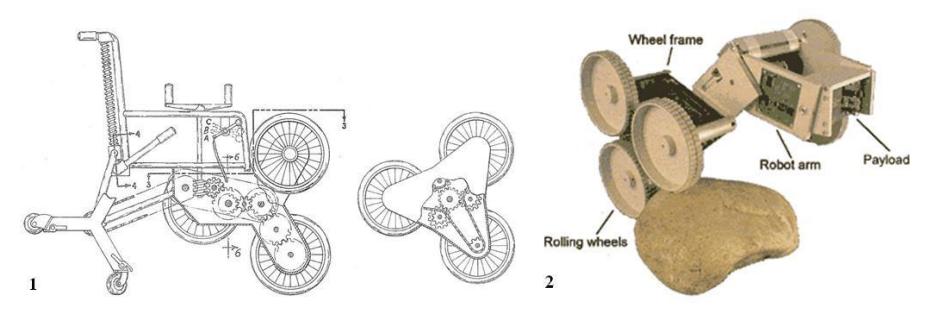
As it was mentioned, our robots both benefit an extraordinary differential steering locomotion system called TTW. The base idea of TTW came from "Space Cat" [9] which itself has a close similarity to J. Flory's stair climbing vehicle [10] (Fig. 11).
8.1. Concept of TTW mechanism
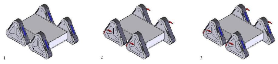
A TTW consists of a track traveling on triangular path and the path itself can semi-actively rotate around its center of shape (which is approximately located on its center of gravity). This combination provides the system three types of locomotion (Fig. 12):
- o Continuous movement: (tracks traveling), suitable for flat grounds
- o Discrete movement: (triangular frames rotation), for rough terrains
- o Combined movement: (both tracks and triangular frames action), for ultra-rough terrains
Note: Since the TTW is not actually a homogeneous body, Center of Gravity (CG) of TTW has a little shift from its Center of Shape [11].
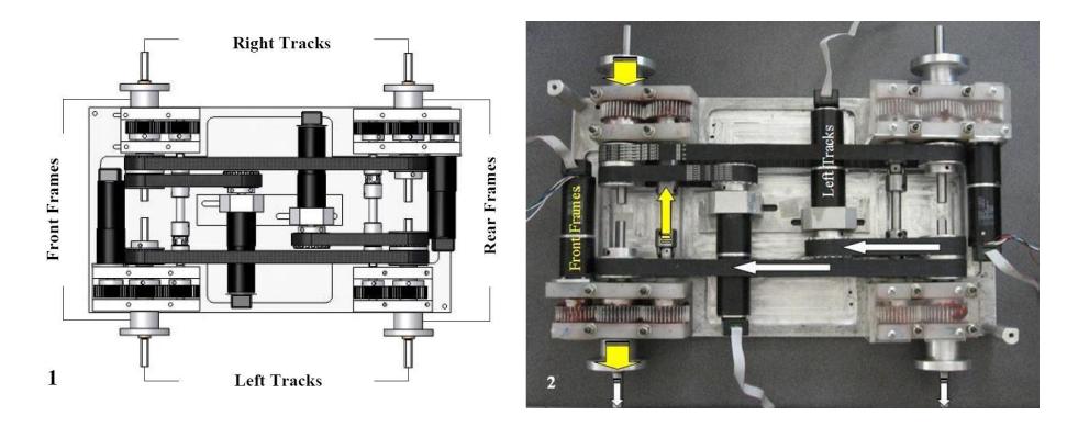
For optimizing the weight and size of system, each side tracks are driven by just one DC servo motor. Therefore, these tracks (both right tracks and both left ones) are synchronous. There is the same matter behind front and rear triangular frames where the front frames are synchronous, so are the rear ones (Fig. 13).
To increase the mobility of system without increasing the complexity of its control process, we prepared surface adaptation capability which consists of two different categories (Fig. 14):
Lateral Adaptation
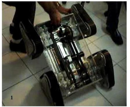
From a kinematical viewpoint, the joint between triangular frames and main body of our robots is semi-active which can be adapted to contact surface passively or be controlled actively. The passive mode is used to mechanically maximize the contact surface in any situation.
Axial Adaptation
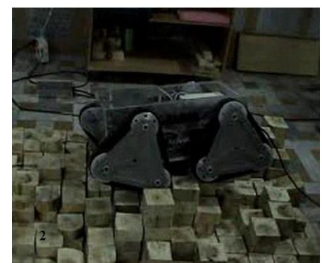
Left frames in contrast with right ones at front or rear of the main body may have phase shift up to 20 degrees for decreasing bumping effect. This is a useful feature at uneven environments like step fields where mechanical dampers are not useful because of low velocity of the system [12].
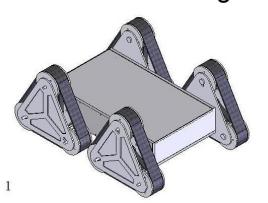
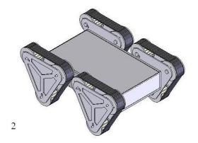
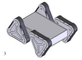
One of the characteristics of tracked vehicles is their high friction force which may be advantage or disadvantage depending on situations. For example, it causes their higher traction force, but the efficiency of tracked systems significantly reduces in turning movements as a result of grater contact surface in comparison with wheeled ones. We managed this problem using the active state of semi-active joint between frames and main body. It provides the following configurations (Fig.15):
- o Positive configuration (suitable for ramps)
- o Negative configuration (horizontal surfaces)
- o Trans configuration (unknown areas)
8.2. Mechanical Specifications
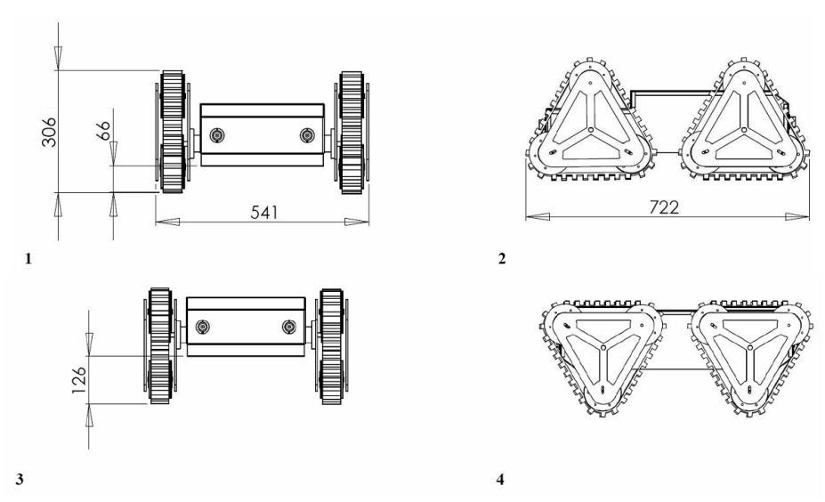
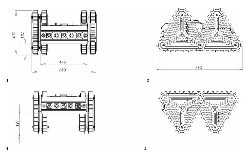
ARIAN uses simple TTW mechanism which was discussed briefly at previous sections. Table 2 and Fig. 16 outline its mechanical specifications.
Table 2. Mechanical specifications of ARIAN
| Property | Value |
|---|---|
| Weight | 28 Kg |
| Nominal power | 540 w |
| Max continuous velocity | 1.1 m/s |
| Max discrete velocity | 1.2 m/s |
| Max velocity | 2.3 m/s |
| Max passed gradient | 0.9 (42 deg) |
| Max payload (at max gradient) | 42 Kg |
META
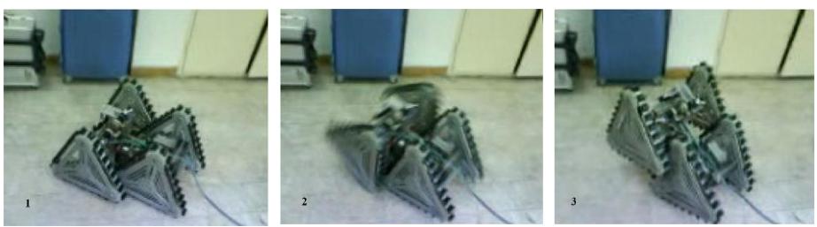
Although META like ARIAN benefits TTW mechanism, it has grate locomotion capabilities in comparison with ARIAN mainly because of its overlapped TTW configuration (Fig. 17).
The followings are mechanical specifications of META:
Table 3. Mechanical features of META
| Property | Value |
|---|---|
| Weight | 32 Kg |
| Nominal power | 600 w |
| Max continuous velocity | 1.1 m/s |
| Max discrete velocity | 0.6 m/s |
| Max velocity | 1.7 m/s |
| Max passed gradient | 0.9 (42 deg) |
| Max payload (at max gradient) | 42 Kg |
9. Other Mechanisms
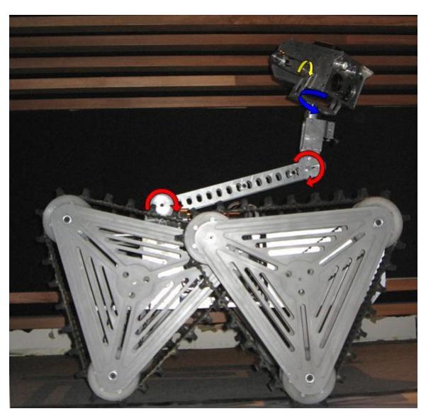
As mentioned, we have designed and manufactured a 3DOF manipulator to hold all victim detection sensors (Fig. 19). Its arm actually is a modified four bar linkage which remains elbow perpendicular to the main body. This exceptional feature provides operator the sense of flying over robot. The joints of manipulator are controlled by reliable motor drivers using accurate shaft encoders as well as an IMU located on the top of VDP and its configurations can be pre-stored in software for easy access.
10. Team Training for Operation (Human Factors)
As it was mentioned, we have constructed the OCU for developing an intelligent and user friendly HRI system, but still handling our robots is not as straightforward as a car driving. To reach such a valuable goal, we have constructed a test site in our laboratory based on NIST 2005 test arena [13] and we use it to constantly improve HRI quality.
11. Possibility for Practical Application to Real Disaster Site
Iran is one of those countries in the world that is subject to frequent earthquakes, and having a real working rescue robot is of high value for our society. It is a highly motivating goal for us to build such a robot. Although, we've tried to use industry grade standards in our robots, they are not as reliable and cost efficient as rescue dogs yet. We are taking our first steps towards this high goal of rescuing human life.
12. System Cost
Following tables present the approximate cost of our systems.
Table 4. Components of ARIAN
| Category | Part Name | Company | QTY | Website |
|---|---|---|---|---|
| Mechanics | Robot platform | 1 | ||
| Gearhead DC motor | Maxon | 5 | www.maxonmotor.com | |
| Gearhead DC motor | Buhler | 2 | www.buehlermotor.com | |
| Motor driver | Maxon | 5 | www.maxonmotor.com | |
| Control | Industrial computer | Advantech | 1 | www.advantech.com |
| Video server | Moxa | 1 | www.moxa.com | |
| Camera (260x) | Zoom | 1 | www.chaiboon.com | |
| Victim detection | IR thermometer | Omega | 1 | www.omega.com |
| CO2 sensor | Vaisala | 1 | www.vaisala.com | |
| Microphone | 1 | |||
| Camera (wide) | Telecom | 1 | www.rf-links.com | |
| Navigation | IMU | MicroStrain | 2 | www.microstrain.com |
| LRF | Hokuyo | 1 | www.hokuyo-aut.jp | |
| Ultrasonic ranger | Devantech | 4 | www.acroname.com | |
| IR ranger | Sharp | 5 | www.acroname.com | |
| Communication | Access point | Proxime | 1 | www.proxim.com |
| Ethernet Switch | DLink | 1 | www.dlink.com | |
| Other | Battery | Kinetic | 12 | www.gitabattery.com |
| Electronics | ||||
| Total Price (US$) | 24,600 ±100 |
Table 5. Components of META
| Category | Part Name | Company | QTY | Website |
|---|---|---|---|---|
| Mechanics | Robot platform | 1 | ||
| Gearhead DC motor | Maxon | 5 | www.maxonmotor.com | |
| Gearhead DC motor | Buhler | 2 | www.buehlermotor.com | |
| Motor driver | Maxon | 5 | www.maxonmotor.com | |
| Control | Industrial computer | Advantech | 1 | www.advantech.com |
| Video server | Moxa | 2 | www.moxa.com | |
| Camera (260x) | Zoom | 1 | www.chaiboon.com | |
| Victim detection | Thermal Camera | Ann Arbor Sensor sys. | 1 | www.aas2.com |
| CO2 sensor | Vaisala | 1 | www.vaisala.com | |
| Microphone | 1 | |||
| Camera (wide) | Telecom | 1 | www.rf-links.com | |
| Navigation | IMU | MicroStrain | 2 | www.microstrain.com |
| LRF | Hokuyo | 1 | www.hokuyo-aut.jp | |
| Stereo Vision | Videre | 1 | www.videredesign.com | |
| Ultrasonic ranger | Devantech | 4 | www.acroname.com | |
| IR ranger | Sharp | 5 | www.acroname.com | |
| Communication | Access point | Proxime | 1 | www.proxim.com |
| Ethernet Switch | DLink | 1 | www.dlink.com | |
| Other | Battery | Kinetic | 12 | www.gitabattery.com |
| Electronics | ||||
| Total price (US$) | 65,300 ±100 |
Table 6. Components of OCU
| Category | Part Name | Company | QTY | Website |
|---|---|---|---|---|
| Hardware | Industrial computer | Advantech | 1 | www.advantech.com |
| Touch screen monitor | Advantech | 1 | www.advantech.com | |
| Portable printer | Canon | 1 | www.canon.com | |
| Joystick | Logitech | 1 | www.logitech.com | |
| Access point | Proxime | 1 | www.proxim.com | |
| Other | Li-Poly battery | Kinetic | 12 | www.gitabattery.com |
| Electronics | ||||
| Total price (US$) | 4,200 ±100 |
References
- Amir H. Soltanzadeh, Ahmad Chitsazan: "Mobile Robot locomotion based on Tracked Triangular Wheel mechanism", final B.Sc. thesis, IAUCTB (2006)
- Player/Stage website: http://playerstage.sourceforge.net
- Johnson: "Don'ts and Do's for Software Developers and Web Designers". San Francisco, Morgan-Kaufmann Publishers, 2000
- Julie A. Adams: "Critical Considerations for Human-Robot Interface Development", AAAI Fall Symposium, Human Robot Interaction Technical Report, 2002
- Bruce A. Maxwell, Nicolas Ward, and Frederick Heckel: "A Human-Robot Interface for Urban Search and Rescue", 2003
- G. Grisetti, C. Stachniss, and W. Burgard. Improving grid-based SLAM with rao-blackwellized particle filters by adaptive proposals and selective resampling, ICRA05
- Probabilistic Robotics' website: http://www.probabilistic-robotics.org
- M. Waleed Kadous, Raymond KaMan Sheh, Claude Sammut: "Effective User Interface Design for Rescue Robotics", 2005
- ASL/ETHZ Autonomous Systems Lab website: http://asl.epfl.ch/index.html?content=research/systems/SpaceCat/spaceCat.p hp
- John F. Flory, Stair-climbing vehicle, 30.450.219, U.S. patents, 1966
- W. Beitz, K H. Kuttner: "Double Handbook of Mechanical Engineering", Springer-Verlag, 1994
- Eugene A. Avallone, Theodore Baumeister: "Marks' Standard Handbook for Mechanical Engineers" , McGraw-Hill, Tenth Edition
- ISD-NIST website: http://www.isd.mel.nist.gov/projects/USAR/competitions.htm