RoboCupRescue 2009 - Robot League Team NuTech-R (Japan)
Tohru NAKAYA
Nagaoka University of Technology
Abstract The proposed robot here "NuTech-R4.1" is a modified version of "NuTech-R4", which was the winner of RRRL Japan open 2008 and in RRRL Thailand open 2008, R4 took the first run-up and the best mobility award. The modifications of R4.1 to R4 are grouser pattern, moving speed, camera installation angle, and environment resistance, which provide better performance.
Introduction
In 2004, CHUETSU great earthquake had occurred in our home town, which depress the local area. Nagaoka Univ. of Technology, a local university, and a NAGAOKA-TEKKOU-SEIKEN, a group of local metal manufactures, had decided to develop a rescue robot and participate Robocup Rescue Robot League(RRRL) in order to cheer up home town people, especially for kids. In 2005 and 2006, we could not score so much. In 2007 and 2008, with our continuous effort, we won RRRL Japan open with the robot NuTech-R3 and R4. R4 also took the first run-up and the best mobility award in RRRL Thailand open 2008.
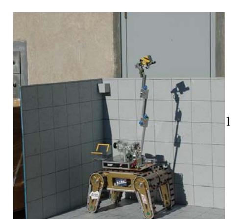
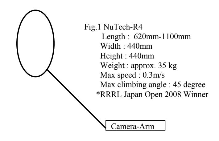
In 2009, this year, we will participate RRRL world championship with NuTech-R4.1, which is a improved version of R4. The detailed specifications are as follows:
1. Team Members and Their Contributions
• Tetsuya KIMURA Manager
• Michihiro NODA Mechanical design • Toshinori YOSHINO Camera arm design
• Takayoshi YAMASHITA Electrical circuit design and programming
• Tsutomu SAITOH Electrical circuit design and programming
• Tohru NAKAYA Operator, Mechanical design
• Sei TAKEYABU Crawler design • Kouji KAWABE Test field design
• NAGAOKA-TEKKOU-SEIKEN Associate development group
2. Operator Station Set-up and Break-Down (3 minutes)
-Set-up
- Boot up the robot (without OS) and the operation system (standard note PC). The boot-up is hot start, so it will take less than a minute.
- Check Internet connection. The connection is based on commercially available TCP/IP software with minimum modification, thus it is robust and it will take less than a minute.
- In total, the robot can start within two minutes.
-Break-down
Just shut down and remove all materials. It will take a minute.
3. Communications
A W-LAN router with 802.11-A (Maker: BUFFALOW, type:LI-TX4-AMG54) is used . Passive tether is also used when W-LAN condition is bad.
| Rescue Robot League | ||
|---|---|---|
| NuTech-R (Japan) | ||
| MODIFY TABLE TO NOTE ALL FREQENCIES THAT APPLY TO YOUR TEAM | ||
| Frequency | Channel/Band | Power (mW) |
| 5.0 GHz - 802.11a | J52,W52,W53(34ch、36ch、38ch、40ch、42ch、44ch、46ch、48ch、52ch、56ch、60ch、64ch) | Unclear but not so big (within Japanese regulation) |
| 2.4 GHz - 802.11b/g | None | None |
| 2.4 GHz - Bluetooth | None | None |
| 2.4 GHz - Other | None | None |
| 1.2 GHz | None | None |
| 900 MHz | None | None |
| 40 MHz | None | None |
| 27 MHz | None | None |
4. Control Method and Human-Robot Interface
-Control Method:
The robots are remote teleoperated by an operator. Automatic control of flipper angle (the flipper will be moved until it touches the ground automatically) is under development.
-Human Robot Interface
A standard note PC and standard GAME-Pad are used for the interface.
5. Map generation/printing
The auto mapping system that uses"Laser Range Finder" is under development.
6. Sensors for Navigation and Localization
-Camera
Visual information is very important for navigation and localization, so relatively a large camera with good resolution (CMOS 3 Mega pixel, lens: focus 2.7mm/F1.8) is installed to the robot. The view angle of the camera is 120 degree, which allows the operator to see the near area (the robot and its near surrounding environment for movement) and the far area (for path planning) simultaneously with one camera. The advantage of this approach is the operator need s not switch the screen or window to see near and far area, which reduces operation time and operator stress.
-Laser Range Finder
We are trying to install Auto Mapping System with Laser Range Finder in the robot. The efficiency of the system has been confirmed with the experiment on a flat ground. The application to the field with RSFs is being carried out.
7. Sensors for Victim Identification
-Camera-Arm
A CCD camera is installed to a 3-DOF hand to see several visual information of victim ( shape, color, movement, sound). The 3-DOF hand in spherical coordination, right-left swing, up-down swing, and extension-contraction, is useful to see the victim in the box, and its specification is as follows: right-left swing(0-360degree), updown swing(0-180degree) and extension-contraction(400mm to 890mm).
-Heat sensor
A heat sensor, which can measure temperature at a point, is installed to measure the victim's body heat.
-Microphone
A microphone is installed to listen the victim's voice.
8. Robot Locomotion
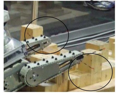
A standard crawler system with front and rear flippers is used. Though this system is widely used for mobile rescue robots, our system has been polished up (crawler size, grouser pattern) during these three years RoboCup Rescue Robot League participation.
Especially, the grouser pattern composed of small bumps with sparse configuration provides good mobility for the random step field(See Fig. 1 and 2).
9. Other Mechanisms
-"Cat whisker" sensor for touching
Some flexible fibers are attached at the edge of the flippers. The fiber has no advanced sensors or data connection to the operator PC, it just attached there. When the flipper is very near to the wall or obstacle, the fiber will bend and the fiber curvature indicates the distance between the flipper and the wall. The curvature can be observed through camera, so this "cat whisker" sensor gives detailed distance information around the flipper edge without complex mechanism. By using the cat whisker sensor, a well-trained operator can follow the wall within 1cm distance.
10. Team Training for Operation (Human Factors)
Visual information understanding is very important for our robot operation. For a well- trained operator with good camera used here, he can 'feel' the robot situation, e.g., inclination, force balance among flippers, through the visual information without supporting sensor information. 50 hours training (2 hours times 10 days) had been applied to the operator when he won RRRL Japan open 2008.
11. Possibility for Practical Application to Real Disaster Site
Some parameters (camera view angle, grouser pattern) will be useful for particular application to the real site.
12. System Cost
For one robot
-Camera (200,000 yen) : Two AXIS 212 PTZ (http://www.axiscom.co.jp/prod/camsrv/prodgd_ptzdome.htm)
-Laser Range Finder(110,000 yen): URG-04LX of Hokuyo Co.
-Mechanical parts (1,000,000 yen): specially ordered
-Crawler (120,000 yen) : Plastic chain for factory use
-Electrical components(300,000)
Total : approx. 2,000,000 yen
13. Lessons Learned
The operator performance is greatly effect to robot performance, so the operator training is very importance.
References
No references listed in this paper.