RoboCupRescue 2009 - Robot League Team P.A.N.D.O.R.A. (Greece)
Antaris Stefanos, Fountas Zafeirios, Nikolaidis Georgios, Papadopoulos Charalampos, Papanikas Georgios, Papazoglou Anestis, Serenis Charalampos, Tsalidis Paraskevas, Tsardoulias Emmanouil, Zolotas Christoforos
Department of Electrical and Computer Engineering Aristotle University of Thessaloniki; Department of Mechanical Engineering Aristotle University of Thessaloniki; Computer Science Department Aristotle University of Thessaloniki; Department of Mechanical Engineering Technological Institution of Serres
www.ee.auth.gr · robotics.ee.auth.gr
Abstract This is the T.D.P. of the P.A.N.D.O.R.A. (Program for the Advancement of Non Directed Operating Robotic Agents) Robotics Team of the Aristotle University of Thessaloniki to sign on for the RoboRescue competition of 2009. We are going to use two tracked platforms aiming at scoring the victims in all the arenas as well as grasping and carrying a specific object, such as a small bottle of water.
Introduction
The P.A.N.D.O.R.A. Robotics Team of the Department of Electrical and Computer Engineering (D.E.C.E.) of Aristotle University of Thessaloniki (A.U.Th.) Greece, was founded in 2005 to participate in the IEEE projects with the support of the D.E.C.E. and consists of undergraduate and postgraduate students of the same as well as other departments of the A.U.Th., interested in the Robotics subjects and aiming at the use of robotics for humanitarian reasons.
During the last years, the team has been working on robotic systems. A robotic arm with four degrees of freedom was developed with the ability to identify, grasp and carry objects of different shape. This robotic arm was awarded with the first prize for the Demo Session in the 2nd National Convention of Electrical and Computer Engineering Students. The team had furthermore participated and had a decent performance in RoboRescue 2008 that gave us the motivation to keep up and improve our project and make an even better performance in RoboRescue 2009, trying to run in all the arenas, including the blue one.
1. Team Members and Their Contributions
Team Mentors
Petridis Vasilios, Professor, Petrou Loukas, Associate Professor, Doulgeri Zoe, Associate Professor
Management Team
Project Management: Papadopoulos Charalampos, Tsalidis Paraskevas
AI Team
Team Leader: Tsardoulias Emmanouil
SLAM: Thomareis Nikitas
Victim identification: Karagiannis Dimitrios Planner: Papazoglou Anestis, Skolarikis Michail
Software Architecture Team
Team Leader: Zolotas Christoforos Programming: Schinas Emmanouil
GUI: Antaris Stefanos
Electronic design Team
Team leader: Serenis Charalampos
Sensors: Papanikas Georgios, Serafi Anna, Panourgia Maria
Integration: Lokas Georgios, Chionidis Ioannis IMU: Felekidis Nikolaos, Zapartas Panagiotis
Mechanical Team
Team Leader: Nikolaidis Georgios
Mechanical Design: Pliagas Christos, Papazi Aspasia
RoboArm Team
Team Leader: Fountas Zafeirios Arm Kinematics: Delakouvia Eleni Trajectory Planning: Gogolou Romina
The team is going to be represented by 11 members in the competition, the names of who are going to be listed in the registration form.
2. Operator Station Set-up and Break-Down (10 minutes)
The number of operators is three. The head operator of the system, who carries the base station case and two backup operators who carry the platform case.
The initialization procedure is implemented as follows:
- Transfer of all the objects in the area and development (3 minutes).
- Activation of the platform and the base station (3 minutes).
- Communication check: so as to check the quality of our Wi-Fi connection (1 minute).
- Systems check: so as to verify that all the systems of the platform work properly (1 minute).
3. Communications
We are going to use W-LAN 802.11a (5 GHz), following your suggestions and we are waiting for channel/band assignment on your behalf.
P.A.N.D.O.R.A. (GREECE) Communications Specifications
| Frequency | Channel/Band | Power (mW) |
|---|---|---|
| 5.0 GHz - 802.11a | 100 |
4. Control Method and Human-Robot Interface
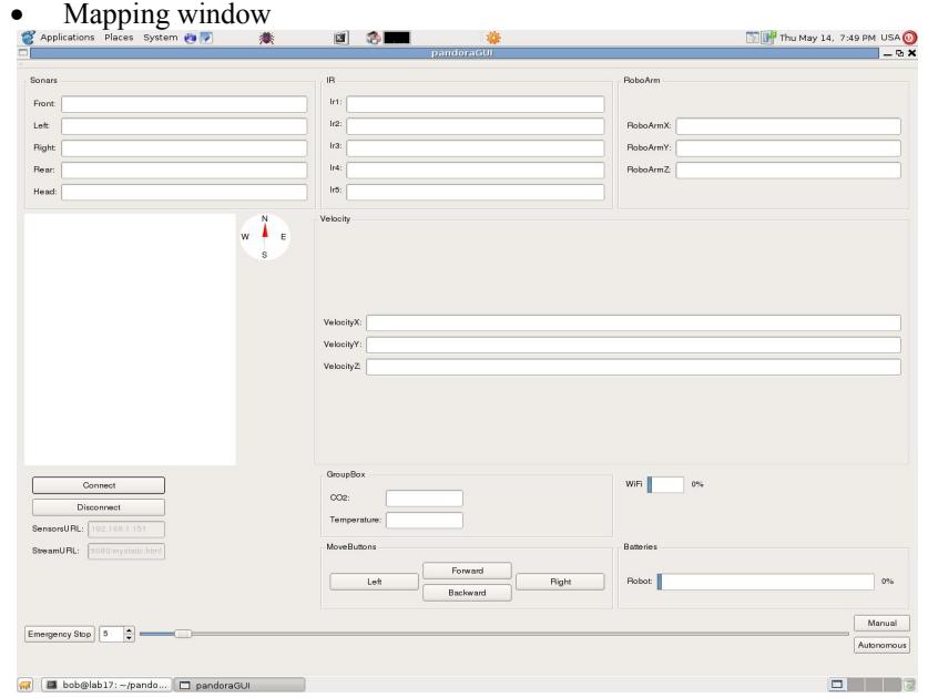
The teleoperated platform runs on manual operation using a Graphical User Interface (Fig.1.). The autonomous platform stops only when the victim is found and expects the operator's handling in order to continue.
The robots are controlled using a wired gamepad or a keyboard.
The readings of the whole operation are shown on a Graphical User Interface. These are:
- Temperature reading
- CO2 quantity reading
- Thermal reading
- Platform inclination on rear and side view
- Distance progress bars of peripheral sensors
- Compass bearing
- Camera Streaming
- Batteries level
- Move buttons
- Way of movement(keyboard or joystick)
- WiFi signal power
- Robot angle state
- Victim found alert
5. Map generation/printing
5.1 Simultaneous Localization and Mapping (SLAM)
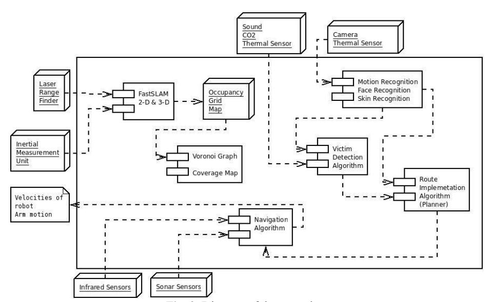
For this purpose we are using an implementation of the Occupancy Grid-based Fast-SLAM algorithm which is based on particle filtering. It is in our immediate goals to implement a 3D version of the FastSLAM algorithm after finishing the necessary tests for the 2D SLAM. FastSLAM requires two inputs: The velocity of the robot and the Laser Range Finder's measurements (Fig.2.). The necessary inputs for the algorithm are obtained from an IMU (Inertial Measurement Unit) and an LRF (Laser Range Finder). The LRF is attached to a custom-made mechanism, which automatically compensates for the platform's inclinations in order to keep the LRF horizontal, to avoid faulty measurements.
5.2 Map generation and environment representation
The FastSLAM algorithm's output is an occupancy grid map of the surrounding area of the robot, which will be further processed to contain the possible victims' locations. Also we will add the appropriate color to determine the free, occupied and unexplored areas of the map. The final map will be sent via WiFi to the base-station for display in the GUI. In order not to overload the WiFi channel, the image will not be sent to the GUI with the same rate as it will be generated.
6. Sensors for Navigation and Localization
Our robotic platform is equipped with several sensors in order to determine its current position and its distance from various objects.
6.1 Laser Range Finder (Hokuyo URG-04LX)
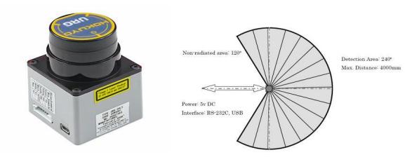
For the map creation we are using the Hokuyo URG-04LX Laser Range Finder (Figure 3). It has a viewing angle of 240° and a detection distance of 20mm up to 4m. The angular resolution is 0.36°, which gives 666 measurements in a single scan, and the linear resolution is 1mm. The accuracy of the measurements varies from 10mm (for distances from 20mm to 1m) to 1% of the measurement for distances up to 4m (Figure 3). It is working on 5V DC (possible error of +/- 5%) and has a current consumption of 500mA.
6.2 Ultrasonic Sensors
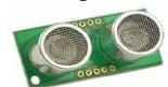
We are going to use 5 ultrasonic SRF05 sensors (Fig.4.), placed around the robot. These sensors use a simple I/O interface for communicating with a microprocessor, sending a pulse whose width is proportional to the distance to the object. Their power consumption is very low (approx. 0.02W). In the front part of the vehicle they will be used to prevent it from bumping into any obstacles. SRF05 can detect obstacles from 3cm to 4m away and can be used as a complement to the Laser Sensor.
6.3 Infrared Sensors
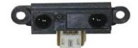
Infrared sensors are placed both on the left and on the right side of the robot and they will cooperate with the sonars in order to give the distance of the robot from any obstacles with good accuracy. We will use GP2Y0A21YK (Fig.5.) infrared sensors. These sensors have a short operating distance from 10 cm to 80cm, so their main task will be to check the close surroundings of the robot. One of them will be used to measure the distance between the bottom of the robot and the ground, so as to start an alarm in cases that the robot is in danger of falling.
7. Sensors for Victim Identification
To identify the victim and pinpoint its location, we are using a number of sensors driven by sophisticated algorithms. Specifically, a stereo vision camera, thermal sensors, a CO2 sensor and three microphones are being used. The sensors results are then fused to determine the behavior of the robot.
7.1 Vision
The autonomous platform is equipped with a stereo vision camera, STOC by Videre Design (Fig.6.). With the implemented software it is able to detect motion, recognize faces and make out skin patterns. Furthermore, the stereo vision processing enhances the platform's ability to calculate distance from the victim.
On the teleoperated platform, the video stream from a single camera is transmitted to the control station for the operator to have a visual sense of the robot's surroundings in real time.
7.2 Temperature
To detect temperature differences in the environment and therefore victims, the robot encompasses FPA thermal sensors. Thus, we are able to compare temperature values in the environment from distance, find fluctuations and make an estimate of a victim's position, if one is found.
7.2.1 Temperature sensor
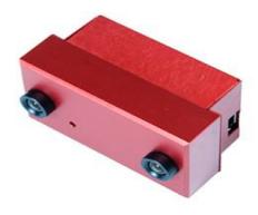
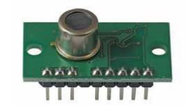
The TPA81 (Fig.7.) is a thermopile array (thermocouples connected in series), together with a silicon lens and associated electronics, which detects infra-red in the 2um-22um range (the range of radiant heat). It can measure the temperature of 8 adjacent points, as well as the ambient temperature, simultaneously. It can detect victim's temperature within 2 meters and its typical field of view is 41˚ by 6. It is connected to a microprocessor via I2C interface and updates its values at a rate of approximately 20Hz.
7.3 CO2 sensor
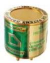
The CO2 sensor (Fig.8.) installed on the robot measures the concentration of CO2 gas in the environment. For the detection of the human respiration we simply track fluctuations in the concentration of CO2 in the air. Our sensor can detect concentration of CO2 gas, from 0 to 50,000ppm. The robot will use the CO2 sensor for the detection of the human respiration, which fluctuates between 30,000ppm and 50,000ppm.
7.4 Sound
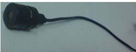
As far as the acoustic sensors are concerned, three electret condenser microphones (Fig.9.) are used for victim identification and navigation. They are mounted on the robotic arm's top, so as to recognize the front left, front right and rear sounds, in order to identify the victim's state by its sound.
8. Robot Locomotion
Our team is participating this year with two platforms, an autonomous and a teleoperated one.
Both platforms are simple efficient and robust.
They are moving based on a tracks system and the teleoperated one is aided by two tracked articulations, on the rear side of the platform, giving it the ability to overcome obstacles, such as stairs, by using those two articulations and have a good mobility. The autonomous platform is designed to be able to overcome simpler obstacles and slopes.
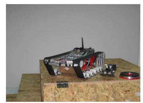
The chassis of each robot is printed on aluminium that makes the assembly of the platforms and the placement of the sensors easier (Fig.10.). Furthermore they are of high rigidity thanks to their compound material and they can even resist to a turning over.
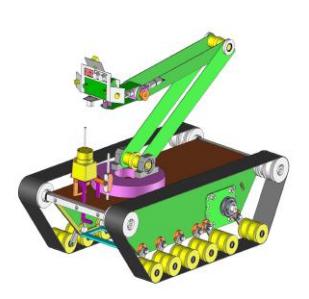
In order to locate victims even if the platform cannot approach them, both robots bear an arm with 5 degrees of freedom (Fig.11.). When the arm is extended it can cover an area of 750mm diameter. Beyond that, the arm of the teleoperated platform has also a gripper able to grasp and carry objects (such as a small bottle of water) in a short distance.
The tracked band and the tracked articulations on each side are moved by brushless DC motors with 50 W of power each.
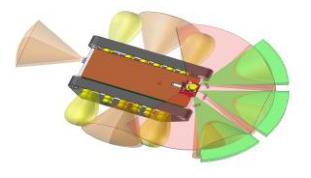
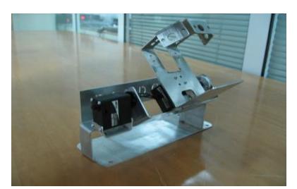
The stabilization mechanism (Fig.12.) is mounted on both robotic platforms, teleoperated and autonomous. It allows the laser and the thermal sensors to stay on the horizontal level, regardless of the robot's inclination. The stabilization is accomplished by two DC-servomotors with fast response.
9. Other Mechanisms
9.1 Stabilizer
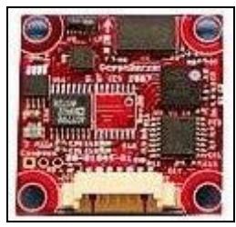
Ocean Server's model OS5000 is a three dimensional compass (Fig.13.) that gives measurements in degrees. It will be used to give us the inclination of the robot in accordance to the starting inclination. The compass will communicate with an AVR microcontroller, through serial RS-232. It will be used in order to stabilize the laser of the robot in the desired position. Its accuracy is lower than 0.5 degrees with resolution 0.2 degrees. Its refresh rate is 40 Hz.
9.2 IMU
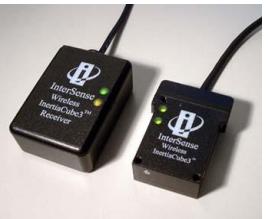
We will use an Inertial Measurement Unit (IMU) in order to have a prediction of the robot's movement and the distance travelled in the arena. The IMU that will be used is the Inertia Cube3 (Fig.14.) which is designed to meet the demands of a mobile, 3- DOF sensor. With broad operating temerature range and low power cosumption, it is ideal for robot tracking in various environments.
9.3 Computing System (Single Board Computer)
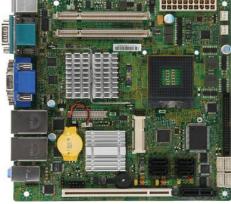
For our computing needs we have built a Mini-ITX system (Fig.15.), placed inside the main body of the robot. The specifications of the system are: MSI IM-GM45 Mini-ITX mainboard, Intel Core2Quad mobile Q9000 processor, 4GB of DDR2 SO-DIMMs, a Solid State Drive with 32GB capacity, all power from a M4-ATX Pico PSU. The board's dimensions are 17x17cm and for peripheral interconnection there are 8 USB ports, 5 RS232 serial ports, a PCI FireWire add-on card for the Stereo Camera, and a MiniPCIe WiFi capable add-on card with 2 pigtails for external antennas. The system's power consumption is estimated at 80Watts at full computing load, without the USB, Serial and FireWire peripherals connected.
9.4 Hardware architecture
Communication between the single board computer (SBC) and the sensor network will be made using a CAN Bus interface. Using a CAN Bus the sensor network will be flexible, allowing sensors to be added or removed with minimum effort. In addition the use of priorities, at the physical layer of the communication, will allow direct access of the SBC to the most critical devices of the network such as the motion controllers. As a higher level network protocol CANopen was selected.
10. Team Training for Operation (Human Factors)
The operator should be familiarized with the structure and the function of G.U.I. He should be able to understand and realize immediately the readings of all sensors. The operator should be familiar to the use of the gamepad and accomplish the test missions in our specially developed arena, which emulates a destruction scene, so as to familiarize himself with and the properties of the platform.
The system is user friendly and easy to operate.
11. Possibility for Practical Application to Real Disaster Site
The robotic platforms have been developed so as to be easy to carry and to be able to overcome complex obstacles. We are going to carry out a lot of tests on real-life conditions so that we make sure that our platforms are going to be able to face a real disaster site with greater efficiency. Our last year's platform was exhibited on EXPO 2008 of Thessaloniki where we were approached by people of the Hellenic Rescue Team and the Institute of engineering seismology and earthquake engineering who showed a lot of interest in using our platforms in real life.
12. System Cost
System Cost Table
| Part Name | Quantity | Price | Website |
|---|---|---|---|
| Mobile Platform | 1 | 3000€ | (custom made) |
| Motors+Cont. | 10 | 4500€ | www.maxonmotor.com |
| Single Board Computer | 1 | 850€ | www.mini-tft.de |
| Laser sensor | 1 | 2300€ | www.active-robots.com |
| IMU | 1 | 1500€ | www.isense.com |
| Cameras | 2 | 1200€ | www.videredesign.com |
| Sensors | 10 | 750€ | www.active-robots.com |
| Batteries | 2 | 400€ | www.hoelleinshop.com |
| Microcontrollers | 5 | 200€ | www.atmel.com |
| Total | 14.700€ |
References
(No references section found in the original paper)