RoboCupRescue 2009 - Robot League Team Pasargad (Iran)
Mohammad Ravandi, Alireza Sheikhjafari, Ali Torabi, Vahid Mehrabi, Soroush Sadeghnejad, Hadi Sadati, Mohammad Mehdi Nabi, Farhad Bagher oskuie, Parisa Dabbaghizarif, Reza Defaei, Hadi Mohammadabadi, Arash Nouri, Yadollah Rasekhipour
Amirkabir University of Technology Mechanical Engineering Department 424 Hafez Ave. Tehran, Iran
Abstract This paper presents the rescue robots that have been designed and built by the Amirkabir University of Technology (Tehran Polytechnic) Pasargad robotic team. The Pasargad team have been an active participant with two semiautonomous robots, namely ASAME1, and ASAME2, and one autonomous robot, AutoASAME. The former robot is designed for the yellow and orange arenas and the latter for orange and red arenas. These robots are equipped with CO2, thermal and sound detection sensors for victim identification. ASAME1 has the map generation ability using laser scanner, while the mechanical structure of ASAME2 enables it to swiftly cross over the obstacles of the red arena .The design of autonomous robot has been finished and its construction is in progress. In what follows we will present the electro-mechanical details and the algorithms that have been adopted in the above mentioned robots.
Introduction
The increasing need of employing robots in environments which are too harsh for humans, has led to vast researches in the field of robotics. In particular, rescue robots have attracted the attention of many researchers worldwide, due to their urgent applications. Due to geographical nature of Iran and the high possibility of earthquakes and other catastrophes, the Pasargad team commenced its research activities since 2005 under the supervision of Amirkabir's Scientific Association of Mechanical Engineering (ASAME). This team have designed and built two semiautonomous robots, ASAME1 and ASAME2, and has finished designing an autonomous one, According to the rules and regulations of international Robocup rescue leagues. Even though actual field tests have not been conducted, we believe that these robots can become suitable for real disaster sites with few modifications.
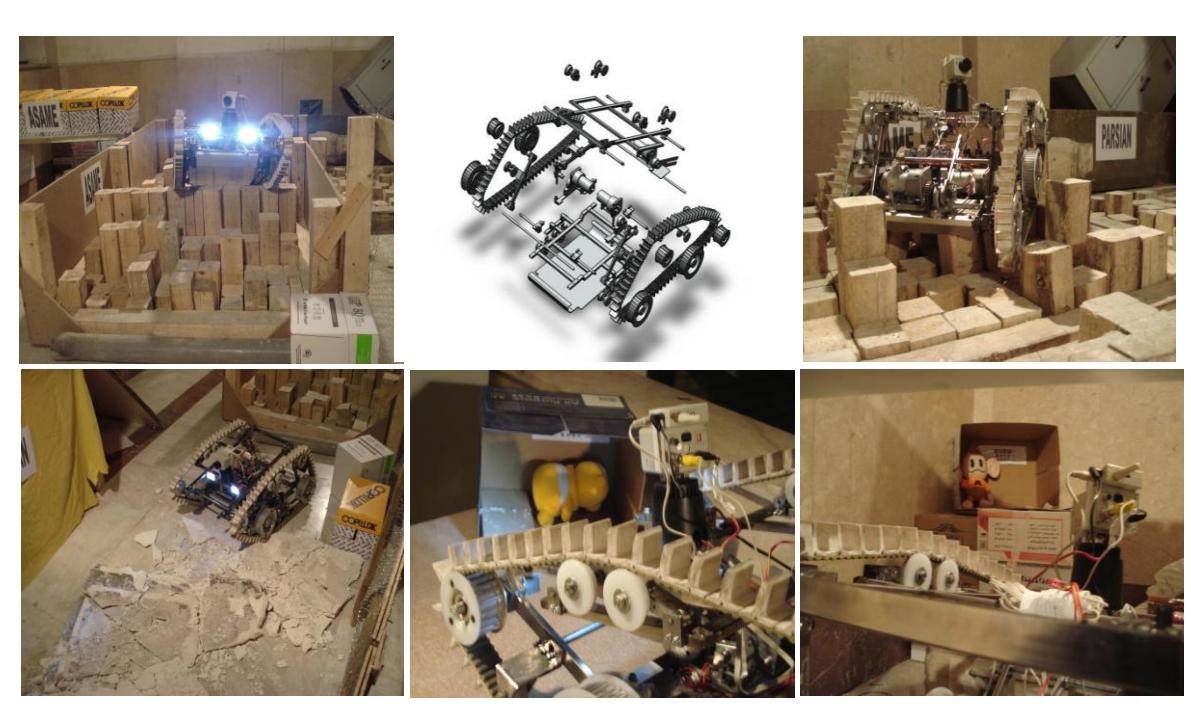
ASAME1 is a remote operation robot that can operate in various unpredictable environments and can cope with rare conditions such as electrical shocks, high moisture, and electronic and communication disturbances. It employs a four linkage mechanism, a cube-like mechanism with varying angles, and moves on a track with eight wheels. ASAME1 is equipped with victim identification and localization sensors and can produce the arena's map automatically with marking the victim location.
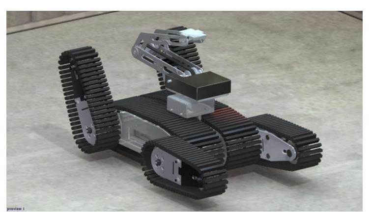
ASAME2 is particularly capable of moving across various difficult environmental obstacles. It has four linear self-locking links that can rotate relative to the main body independently of each other. A mechanism has been designed on top of this robot that facilitates the movement of camera and the group of sensors. This mechanism has three degrees of freedom and can cover 600mm above the robots surface.
The control systems of these robots have been designed in such a way that enables the operator to switch between them at any moment.
The AutoASAME is a fully autonomous robot. It has laser scanner and image processing to explore environment, determine the path, and detect victims. (Under construction)
Both robots are equipped with various sensors for identification of victim's status, e.g. thermal and CO2 sensors, cameras, and sensors for movement and sound detection. We composed a localization system by an electronic compass, encoders and an acceleration sensor.
1. Team Members and Their Contributions
Mohammad Ravandi Team leader Ali Torabi Parizi Mechanical design Vahid Mehrabi Mechanical design Soroush Sadeghnejad Mechanical design Yadollah Rasekhipour Mechanical design Hadi Sadati Mechanical design Hadi Mohammadabadi Mechanical manufacture Parisa Dabbaghizarif Mechanical manufacture Alireza Sheikhjafari Electronics design Farhad Bagher oskuie Electronics design Reza Defaei Communication establishment Arash Noori Communication establishment Mohammad Mehdi Nabi Programming and software development Dr.M.R Razfar Technical Adviser
2. Operator Station Set-up and Break-Down (10 minutes)
Regarding the limited amount of time for preparation of robots and the team's experiences in former international leagues, the operator system and the robots have been prepared distinctly. Each robot is ready to receive the operator commands as soon as it receives the signal from the on/off key. The operating system includes a laptop, a joystick, manipulator (for camera robotic arm), and a communication antenna that have been collected in a single unit for quick installation. After running the program and establishing the connection between the two robots, each robot can be controlled separately.
3. Communications
A wireless communication has been established using W-LAN802-11b/g communication network at 2.4GHz frequency. The information is gathered in the central processing unit of the robot via a hub-switch. The processed information is sent to the operator using Access Point. In case the communication fails, the robot will intelligently switch to autonomous mode until the reestablishment of communication.
Rescue Robot League - Pasargad (Iran) Communications Specifications
| Frequency | Channel/Band | Power (mW) |
|---|---|---|
| 2.4GHz- 802-11b/g | 1-14ch | 10 (mW) |
4. Control Method and Human-Robot Interface
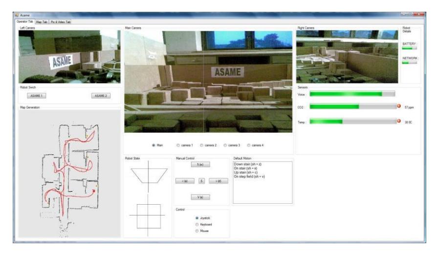
The two robots are controllable in both automatic (non autonomous) and manual modes. In the automatic mode, the robots gather and transfer information using an intelligent program and in case any problems occur in the automatic control system, the type of the error is reported to the operator. In the manual mode, the operator can send his signals to each of the robots, using joystick, keyboard, and manipulator, and observe the gathered information of the robot through the monitors and gages. The operator can observe the recordings of three cameras of the robot at any instant via three windows on the display monitor, and can switch between any of the five cameras if required. Other information that is available to the operator at any instant include the amount of carbon dioxide, temperature, charge of batteries, the orientation of robot relative to north pole, the angle between the robot links and main body, the amount of sound signals of the environment, and the instantaneous graphical shape of the robot. The program also enables the operator to perform some predetermined tasks such as climbing up and down stairs and ramps.
5. Map generation, Navigation and Localization
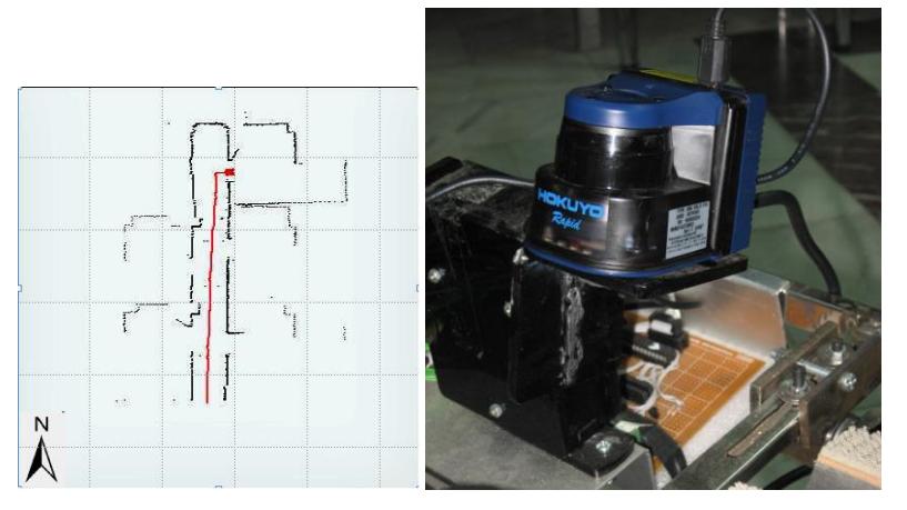
For orientation and mapping a simple algorithm is used. This algorithm takes and combines it's inputs from encoders, accelerometers, compasses with laser range finder.
laser scanner (Laser range scanner Hokuyo UGB-04LX-F01)
To map, the sensor is used, the angle of sight of this sensor is 240 degrees with accuracy of 0.36 degrees with a speed of 100 scans per second and the length of sight is from 0.02 to 6 meters with accuracy of 1mm.
Three parameters will be identified in this map:
- Environment map
- Robot exploring path
- Victim location
Using the motor encoder, the displacement of the robot will be identified. The output of the encoders needs to be modified by using the accelerometer due to these reasons:
- Heavy shock
- Slipping of the robot in ramp field.
- Another error of the encoders output.
The procedure of this method is as follows; the output of accelerometer will be integrated two times in each period of time. With this action the displacement will be known. This displacement will be compared with encoders output and at the end the encoders output will be modified. Laser scanner will be placed on a three degree of freedom (3-DOF) pan tilt. This pan tilt will hold the laser scanner in horizontal state throw north direction. In fact, it is used to minimize the probability of errors. X and Y motion will minimize the error that may occur due to trapping an exploring in ramp arenas and the Z motion will decrease the time of calculation due to robot rotation.
6. Sensors for Victim Identification
Compass
In this robot three different compasses with 3 different assumed north directions are used, each north differs by 45 degrees relative to the others. This has been done to improve accuracy and reduce erroneous results.
Ultrasonic
In the left and right sides of the robot, in which the operators sight is limited ultrasonic devices are used to find blocks or objects.
Thermal sensor
Three TPA81 sensors which are none contact sensors are used.
CO2 sensor
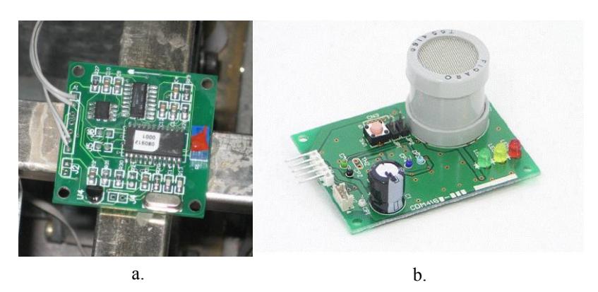
The CO2 sensor used is CDM4160-MOO that has the ability to measure CO2 levels up to 8000 ppm. (Fig.5-b). The microcomputer takes data and renews it once per second. The processor calculates CO2 concentrations based on the difference between current sensor output and a baseline value.
Microphone
The cameras installed all have microphones and these microphones are used to gather sound.
Camera
Three cameras will be used in each robot:
Main camera: Panasonic BB-HCM580 IP surveillance camera with pan tilt 21x optical zoom, low light capability and motion detection. This camera will be assembled on camera arm. By using this camera; the robot can identify the victim main situation.
Camera 2: It is used to show the left side of the robot.
Camera 3: It is used to show the right side of the robot.
Block diagrams
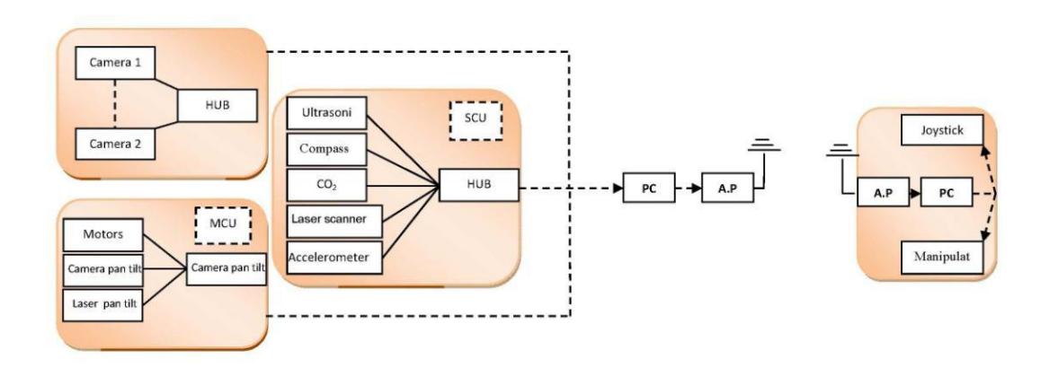
7. Robot Locomotion
The Pasargad team will compete with two semiautonomous robots with tracks in this competition.
As robots with tracks perform better than robots with wheels in difficult and variable paths in competitions, the choice of using tracks seems to be the best choice. Robots that have tracks or chains for movement can easily traverse obstacles that would stop robots with wheels. Some of these obstacles are:
- Very soft floors: sandy, soft snow and muddy environments
- Obstacles with certain sizes that can get caught between the wheels
Stones and paths with crevices
Track robots have this capability of motion but at the price of the difficulty of design and building, cost and lower efficiency. So tracks are a good option here but they are not always the best choice.
7-1 ASAME1 Designed Mechanism
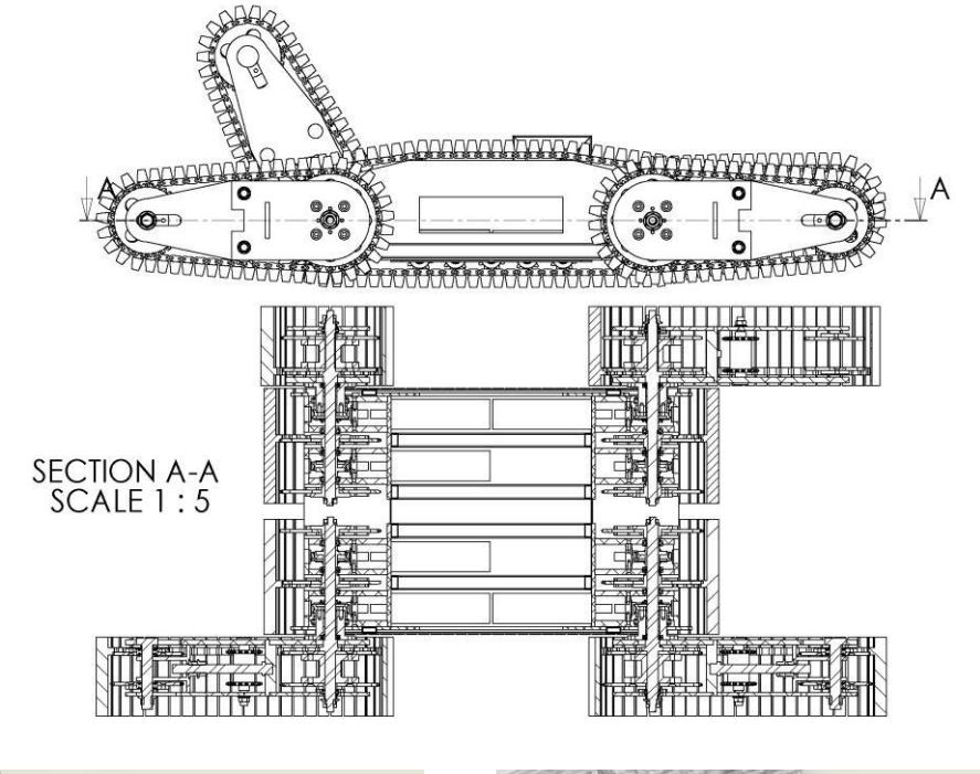
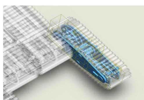
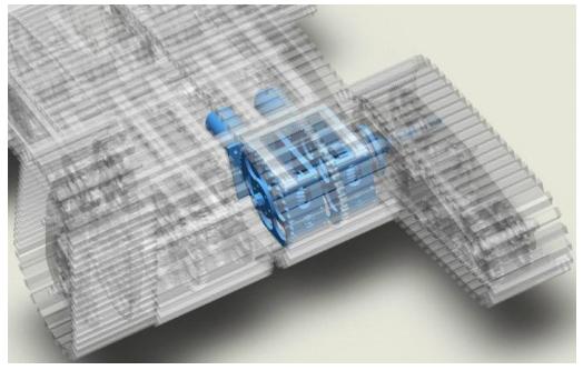
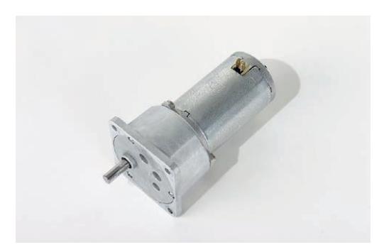
For the track mechanism of this robot, each wheel has a gear like profile of the standard type XL on its outer surface which engages the same profile in the inner surface of the tracks. On the outer surface of the tracks cuboids of average height of 35mm are places 30mm apart to produce the capability of engagement with different obstacles. Each of the pair of propulsion wheels has two motors of the type Buhler-1.61.050.446 on either side (Fig.6). These motors are 12 volts with direct current, and each has a gear box with a ratio of 1:96. The speed limit of the motors is 2400rpms and maximum torque output of 46.3mN.m. The choice of motor was based on the calculations relating to the dynamics of the robot as well as a comparison of motors provided by different manufacturers.
The robot has the capability of lowering its tracks to increase the surface of contact of the robot with different obstacles. This is achieved by a Buhler motor of the type 1.61.050.448 with a gear box designed by the team with a ratio of 1:3.
7-2 ASAME2 Designed Mechanism
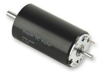
ASAME2 is a robot with the capability of traversing the most difficult of obstacles. This robot has four linear arms which have the ability to rotate freely relative to the main body of the robot, even though they have been designed to be self locking. The robot has six worm gear boxes each with its own motor, so that two motors move the robot itself and the other four rotate the arms. Other advantage is its fully wrapped shape with tracks. It causes the robot cross step field easily. The motors were purchased from MAXON Motor Co. of the model 148867.
For this robot, an arm mechanism has been designed to move the camera and sensors. This arm has three degrees of freedom. A model will be built of this arm, because of its high degree of freedom (manipulator), so that the operator can achieve his desired form with speed and ease.
7-3 AutoASAME
The AutoASAME is a 4WD robot that uses two Buhler motors to provide forward, backward, and rotation motion
8. Team Training for Operation (Human Factors)
Two types of practices have been foreseen; The first type is to familiarize the team with the completion, its environment and the way information must be gathered from this environment. The second type involved specialist learning and practicing for the members involved in control and servicing for electronics, robotics and the computer of the robots. The exercises involving assembly and repair of the robot before the competition can also be included in this section.
9. Possibility for Practical Application to Real Disaster Site
Even though the robot has not been tested in realistic environments, the team believes that based on tested performed in simulations of real environments and competitions the robot can perform adequately in these environments.
Still, realistic situations were taken into account during the entirety of the design process. The mechanical equipments and capabilities of ASAME2 stand it in good stead to traverse environments with small stones, surfaces with different slopes, areas with discrete stairs, and unstable uneven surfaces. It can also be assembled and disassembled very easily and this can also be done by an untrained person and thereby also transported to the area easily and quickly. Also the body of both robots can take the stains of a real situation.
10. System Cost
System Cost
| Item | Qty | Price/Pcs | Price |
|---|---|---|---|
| DC motor | 6 (Maxon) | 570 $ | 4045 |
| 5 (Buhler) | 125 $ | ||
| Leaser scanner | 1 | 2560 | |
| Laptop | 3 | 500 $ | 1500 |
| IP camera | 2 | 850 $ | 1700 |
| Webcam | 5 | 20 $ | 100 |
| Thermal sensor (TPA81) | 2 | 400$ | 800 |
| CO2 sensors | 2 | 150 $ | 300 |
| Other sensor | 1000 $ | 1000 | |
| Manufacture | 4000 $ | 4000 | |
| Staple | 1100 $ | 1100 | |
| Total | 17,105 $ |
References
- Jorge Angeles," Fundamentals of Robotic Mechanical Systems: Theory, Methods, and Algorithms, Second Edition", Springer-Verlag New York, Inc., 2003
- Roland SIEGWART, Illah R. NOURBAKHSH, "Introduction to Autonomous Mobile Robots", Massachusetts Institute of Technology, 2004
- J.E.Shigley, C.R.Mischke, "Mechanical Engineering Design", fifth Edition, University of Michigan, 1989
- Richard S. Hartenberg, "Kinematic Synthesis of Linkages", MacGraw-Hill Book Company
- Maxon Motor. DC Motor. [Online].
- V. Nguyen, A. Martinelli, N. Tomatis, R. Siegwart. A Comparison of Line Extraction Algorithms using 2D Laser Rangefinder for Indoor Mobile Robotics. In Proc. of the IEEE/RSJ, IROS, 2005.
- www.figarosensor.com
- http://www.hokuyoaut.jp/02sensor/07scanner/urg.html
- http://panasonic.co.jp/pcc/products/en/netwkcam/