RoboCupRescue 2009 - Robot League Team Pelican United(JAPAN)
Kazunori Ohno, Tomoaki Yoshida
Tohoku University Graduate School of Information Sciences, Tohoku University 6-6-01 Aramaki Aza Aoba, Aoba-ku, Sendai, 980-8579 Japan; Chiba Institute of Technology Future Robot technology center 2-17-1 Tsudanuma Narashino Chiba 275-0016 Japan
http://www.rm.is.tohoku.ac.jp/
Abstract This paper describes our team organization and our new robot 'Kenaf2' that is a successor of crawler robots with flippers such as TP07, Hibiscus, and Kenaf. In this year, our team will compose of 3 sub-teams. The new robot "Kenaf2" has 6 DOF: a whole crawler body and four flippers. It will be more stable, more powerful, and easier to operate in rubble. We've done much onsite training of our robot with people from fire depot, and found flaws to be improved. The Kenaf2 is the answer to it. We will also improve the ability of map construction and autonomy.
Introduction
This paper describes our team organization and our new robot 'Kenaf2' that is a successor of crawler robots with flippers such as TP07, Hibiscus, and Kenaf [1]. In this year, our team will compose of 3 sub-teams: Chiba Institute of Technology, Tohoku University and AIST. The new robot "Kenaf2" has 6 DOF: a whole crawler body and four flippers. It will be more stable, more powerful, and easier to operate in rubble. We've done much on-site training of our robot with people from fire depot, and found flaws to be improved. The Kenaf2 is the answer to it. We will also improve the ability of map construction and autonomy.
1. Team Members and Their Contributions
Our team "Pelican United" is organized with members from Tohoku University, Chiba Institute of Technology, and Advanced Industrial Science and Technology.
Eiji Koyanagi Mechanical design
Itsuki Noda Integration of sensing information into GIS
Keiji Nagatani High level locomotion command system
Satoshi Tadokoro Adviser
Kazunori Ohno 3D Mapping and autonomous control algorithm
Tomoaki Yoshida System and Software architecture design Daisuke Inoue Rollover and fall avoidance algorithm Ken Sakurada Automatic sub-crawler control algorithm
Sasushi Hata Autonomous control algorithm Masashi Yamazaki Autonomous control algorithm
Eric Rohmer Automatic sub-crawler control algorithm
Eijiro Takeuchi Multi-robots SLAM Seiga Kiribayashi Mechanisms assembly
Yoshito Okada Automatic sub-crawler control algorithm
Naoki Tokunaga Autonomous control algorithm
Hidehisa Akiyama Integration of sensing information into GIS
Masatsugu Kawamoto Mechanisms assembly Hidehisa Akiyama GIS and Multi-robots SLAM Student member Mechanisms assembly Ikuko Tanimura Travel and Video Support
2. Operator Station Set-up and Break-Down (10 minutes)
The operator station is packed in one middle size Pelican case, and the robot is also packed in two middle size Pelican cases. Total weight will not exceed 100kg, and considering that the pelican cases are equipped with wheels and handles, it is possible to carry by an operator himself.
Most time consuming step of the set-up process in the operator station is to boot up the PCs , and establish wireless connection between the station and the robot. We will save a map data as some electrical data, and will submit it. It is easy for Robocup stuffs to share the victim's information.
We will plan that the number of operator is only one. The operator will control some robots during the competition.
3. Communications
We use IEEE 802.11a (5.2GHz Band) for both control and sensing (including video, Laser Ranger Finder etc) communications. In Japan, all WLAN RF power is restricted to 10mW. Therefore our robots and operator station are also use 10mW of RF power.
Rescue Robot League
| Rescue Robot League | |
|---|---|
| Pelican United (Japan) |
Frequency bands used by Pelican United
| Frequency | Channel/Band | Power (mW) |
|---|---|---|
| 5.0 GHz - 802.11a | 36-64 | 10mW |
| 2.4 GHz - 802.11b/g | ||
| 2.4 GHz - Bluetooth | - | |
| 2.4 GHz - Other | - | |
| 1.2 GHz | - | |
| 900 MHz | - | |
| 40 MHz | - | |
| 27 MHz | - |
4. Control Method and Human-Robot Interface
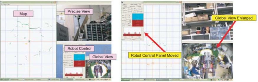
The locomotion of the robot is controlled with single popular joy-pad equipped with 2 analog stick and 12 digital bottoms. The operator recognizes a surrounding environment of the robot trough video information of a bird view camera, and range data from laser range scanners. With the baseline system, all decisions should be made by the operator, and no autonomous mobility. However, we are working on autonomous control of sub-crawlers and autonomous exploration system. We will use these new technologies on the RoboCup competition in China.
A pan-tilt-zoom camera on the robot will be controlled using touch panel on the video display. The touch panel seems very handy than usual pointing device such as mouse or trackball, especially when the operator is not sit down on a chair.
Information expected to be shown such as video from several cameras, range data, gradient sensor readings, is too much for single LCD panel. We organize this information fit with two LCD panel, and built such operator station.
5. Map generation/printing
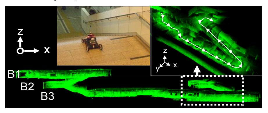
The robot will be equipped with at least two laser range scanners, one for horizontal scan and another for vertical scan. With range data from such range scanners and posture information from the IMU such as gyro sensors and gradient sensors, our robot will be equipped with a semi-automatic 2D/3D hybrid mapping system (2D SLAM with 3D range data).
6. Sensors for Navigation and Localization
For odometry based navigation, each motor is equipped with incremental encoder. Also, 3-axis gyro sensor, 3-axis gravity sensor are placed inside the robot. To compensate odometory error, 2D SLAM using horizontal laser range scanner will be performed beside with manual compensation by the operator himself. To recognize environment by the operator, a bird-view camera, and pan-tilt-zoom camera is used. The configuration of these cameras is almost same as last year model.
7. Sensors for Victim Identification
A pan-tilt-zoom camera is used for victim identification. For supplemental use, a thermal camera and CO2 sensor are also mounted on top of the robot. Bi-directional audio communication will be implemented until the competition.
8. Robot Locomotion
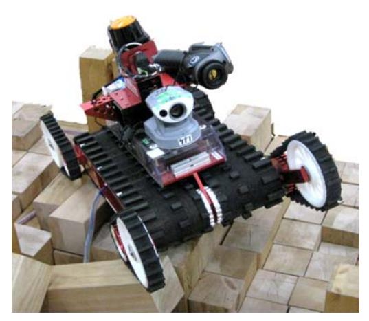
The robot is equipped with 2 full-body crawlers and 4 sub-crawlers for locomotion. We recognize the problem with last year model, and re-design to improve mobility on rough terrain. Main improvements are as follows: Powerful motors are used for locomotion. The center of gravity of Kenaf2 is lower than one of Kenaf. Material of Crawler is changed new one. The new model of our robot should work better than kenaf, "which is winner of 2007 RoboCupRescue mobility competition", on step fields.
9. Other Mechanisms
The structure of our robot is designed the maintenance task in mind. We use safe and powerful batteries for the Kenaf2, which can be carried by airplane.
10. Team Training for Operation (Human Factors)
Our operator is trained on the training facility of fire depot periodically. In such event, volunteers from fire depot also operate our robot. They operate our robot well, with a few minutes instruction. The fact shows our robot requires almost no training to operate.
11. Possibility for Practical Application to Real Disaster Site
We've already used a base model of our robot on the site at the Mid Niigata Prefecture Earthquake in 2004. Our robot was used to check damages of underground pipe from inside of it.
12. System Cost
Now, we sell base system of Kenaf2 at about $22000(US) for Japanese researchers in JAPAN, because the system is still improved in our team, and we can only support them in Japanese. However, we are making Kenaf2 with a Japanese company as product. We are planning to sell the Kenaf2 at cheaper price in the world.
13. Lessons Learned
In the last competition, we modified our hardware and software for the debug and the improvement. We think that the our robot will change according to the field and the rules during the competition. Especially, software will change drastically because the rules often change during the competition.
References
- Tomoaki Yoshida, Eiji Koyanagi, Satoshi Tadokoro, Kazuya Yoshida, Keiji Nagatani, Kazunori Ohno, Takashi Tsubouchi, Shoichi Maeyama, Itsuki Noda, Osamu Takizawa, Yasushi Hada, "A High Mobility 6-Crawler Mobile Robot 'Kenaf'," Proc. 4th International Workshop on Synthetic Simulation and Robotics to Mitigate Earthquake Disaster (SRMED2007), pp.38 , 2007.
- Kazunori Ohno, Shouich Morimura, Satoshi Tadokoro, Eiji Koyanagi and Tomoaki Yoshida, "Semi-autonomous Control System of Rescue Crawler Robot Having Flippers for Getting Over Unknown-Steps," Proc. of IEEE/RSJ Inc. Conf. on Intelligent Robots and Systems,pp.3012-3018, 2007.
- K. Ohno, T. Kawahara, and S. Tadokoro, A˛gDevelopment of 3D Laser Scanner for Measuring Uniform and Dense 3D Shapes of Static Objects in Dynamic Environment," Proc. of the 2008 IEEE International Conference on Robotics and Biomimetics, 2008.
- K. Nagatani, N. Tokunaga, Y. Okada, and K. Yoshida, "Continuous Acquisition of Three-Dimensional Environment Information for Tracked Vehicles on Uneven Terrain," Proc. of the 2008 IEEE International Workshop on Safety, Security and Rescue Robotics, 2008, pp. 25–30.