RoboCupRescue 2009 - Robot League Team Resquake (IRAN)
Ehsan Mihankhah, Ehsan Aboosaeedan, Arash Kalantari, Hesam Semsarilar, Soheil Mottaghi, Masood Alizadeharjmand, Abbasali Forouzideh, Mohammad Ali Motie Sharh, Shervin Shahryari, Navid Moghadmnejad
Faculty of Electrical Engineering of K.N.Toosi University of Technology
http://saba.kntu.ac.ir/Resquake
Abstract Through this paper we introduce Resquake's recent work on implementing tele-operated and autonomous Rescue Mobile Robots. Major mechanical designs will be discussed as well as new tele-operated and also autonomous mobile robot. A new approach for mapping and localization will also be discussed. We are developing more effective systems for 2009 taking advantage of our precious experiences from Lisbon, Osaka, Bremen, Atlanta, Suzhou and regional competitions.
Introduction
Resquake team-work on mechanical structure for totally destructed environment (Red Arena) has been mainly focused on new version of our innovative mechanism "Silver" which was introduced in RoboCup2005-Osaka and was awarded as "Best Design 2nd Place". Silver2009 mechanism is now even more reliable in step-field battling and stair-climbing operations due to the changes that has been made to it. Larger scale and more powerful actuators are the most important changes. There has also been a great improvement in electrical designs in both control and power circuitries. The above platform is a highly flexible and programmable hardware for being controlled by the high-level software. The innovative user interface that was introduced in RoboCup2006 – Bremen and was awarded as "Best Operator Interface" is getting even more effective for Graz.
Localization and 2D mapping which in mainly based on LASER scanner data is another project to be followed and we hope it will be at least available on our yellow arena robot.
1. Team Members and Their Contributions
Ehsan Aboosaeedan Electrical Design Soheil Mottaghi Electrical Design • Arash Kalantari Mechanical Design And Simulation • Hesam Semsarilar Mechanical Design And Implementation • Navid Moghadamnejad Mechanical Design And Simulation • Shervin Shahryari Mechanical Design And Implementation • Ehsan Mihankhah PC-Based Control and Software Developer, Operator, Team Leader • Masood Alizadeharjmand PC-Based Control and Software Developer • Mohammad Ali Motie Sharh PC-Based Control and Software Developer • Dr. S. Ali A. Moosavian Advisor • Dr. Hamidreza. D. Taghirad Advisor • Dr. Alireza Fatehi Advisor
2. Operator Station Set-up and Break-Down (10 minutes)
Everything is packed in a toolbox (the Operator's Laptop and printer and other accessories like pedal and throttle, microphone, mouse, a bunch of papers and writing tools …). Operator will do nothing. We have 4 members of the team in setup and Break-Down time. Each person will setup the parts in the box he is carrying. We estimate a 2 minutes setup and a 2 minute Break-Down process. Shervin and navid will carry the toolbox. They will plug the Laptop accessories (pedal-throttle, mouse, printer …). Ehsan (Aboosaeedan) and Soheil will setup the robots. Ehsan (Mihankhah) is the operator. He keeps watching the setup process and verifies the setup and break-down. Break-down procedure is similar to setup procedure.
3. Communications
All Wireless communication is implemented in 5 GHz range using IEEE802.11a wireless LAN cards and access points. Other frequency ranges are not occupied. We are using Gigabyte PCMCIA LAN cards and Planet WDAP2000PE access point. Video, audio and data are transmitted by sending packets on wireless network. It is possible to set the wireless system to work on one channel and do not disturb other channels and frequencies, but we can change to any 802.11a channel (almost all possible channels) in case we are asked to. The signal strength is less than 60dB. Here we discuss the software code for video, audio and data transmission. We use C#.NET 2009 as our high-level programming language.
Data Transmission
We use windows sockets for data transmission. Using System.Net.Sockets namespace in C#.NET we have all the classes and events we need to transmit data on LAN. As the program should do many things other than listening to sockets, we need to add threads listening to sockets while the CPU is free for doing other tasks. So, the high-level program is actually a multi-threaded program. In the program running on operator Laptop, one thread captures pedal-throttle data and sends operator commands to the program on the robot. A thread in the program on robot is assigned to get the mentioned data and send them serially to the interface circuit. This is just the same for speech commands and keyboard commands. There are other threads in robot program that are assigned to get data from sensors (Pyrometer, LASER scanner, rotary encoders,…) and send them through other sockets for the program in operator side.
Video Transmission
Video transmission is the most critical part of communication as we need large bandwidth and a reliable connection (that usually does not exist in RoboCup events) to send video streams. The problem with video streams is that we have to buffer them before showing and this means to accept some delay. Loosing connection adds more delay to the video as the stream needs to be recreated every time we lose the connection. We can solve this problem by sending frames instead of streams. If we can send more than 12 frames in a second, then we have a live (almost no delay) video and we should not worry about rebuilding the lost stream. We may lose some frames that mean loosing frame rate but we still have the video. So, what we are doing at the moment is sending frames through LAN with VideoCapX ActiveX control (for more information see [1]) The key properties and method names for sending and receiving frames over LAN are: ServerMode, SendFrame and ReceiveFrame. The C# source code could be found at the fathsoft website. We have been using this method since RoboCup2005-Osaka and it seems to be working well.
Audio Transmission
In Transmitting Audio information, short delay is not much critical. What we really need from the audio is to hear whether there is a sound or not. So the delay is not much critical. We have better have a high quality sound and just accept an about a one second delay. We use Windows Media Encoder SDK for sending audio streams over LAN. (For more details see [2]).
Table 1. Table of Occupied Radio Frequencies
| Rescue Robot League | |||
|---|---|---|---|
| Resquake (IRAN) | |||
| Frequency | Channel/Band | Power (dB) | |
| 5.0 GHz - 802.11a | One - Fixed on Any Asked Channel |
Less Than 60dB |
4. Control Method and Human-Robot Interface
Resquake graphical operator interface is a very simple and user friendly environment that helps our operator to concentrate on finding victims instead of driving. The interface does not confuse the operator by different videos from different aspects. The operator usually needs one or two videos at the same time to decide what he should do and where he should go. So, the interface provides the operator with two videos on screen. Giving the operator the chance to move one camera to a desired position and orientation is far better than adding many cameras in many directions. So, we have installed the main camera on a manipulator. Having one or two other fixed cameras that provide useful views that are unreachable to get to with the main camera are sometimes useful. So the operator can choose one of these fixed cameras on his graphical user interface. Graphical user-interface also allows the operator to monitor network sockets and commands that are sent to the robot in the status bar of the main window. Heat and the amount of CO2 are graphically (with Gauges) shown to the operator so he can easily sense the change without keep watching the numbers. Operator can fill out the victim sheet inside the graphical interface and give a clean printed report.
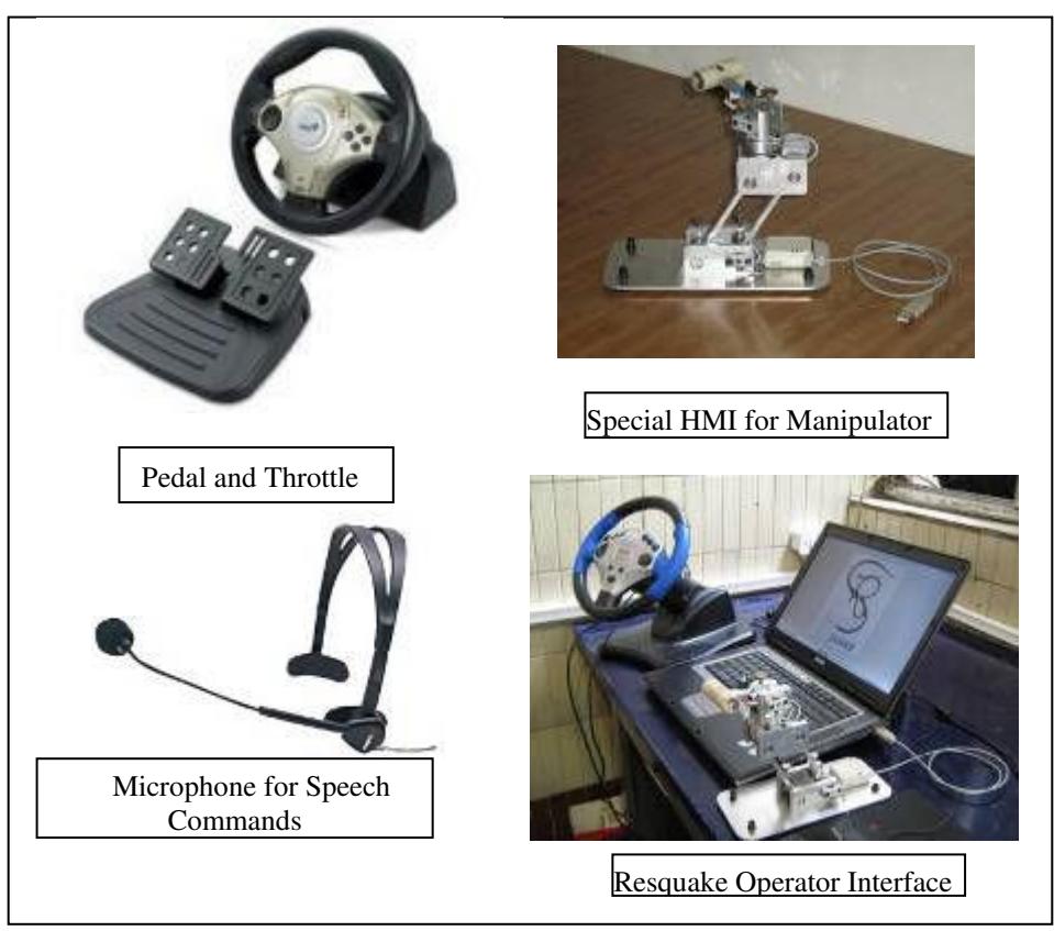
Silver (Our Red Arena Robot) is a highly featured mechanical and electrical hardware. Assigning keyboard shortcuts for the numerous possible commands makes it difficult for the operator to control the robot. We have a very effective operator interface that helps our operator to very easily control the complicated structure. Pedal and throttle are familiar interfaces. Apart from operator hands, operator feet are also helping the operation. By adding speech commands, we are adding other operator ability for sending commands to robot. In figure 1 the operator interface could be seen.
5. Map generation/printing
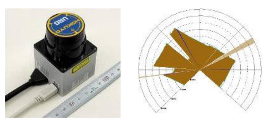
We are working to generate 2D map in surface. Main sensor is a Hokuyo URG 04LX (See Figure 2).
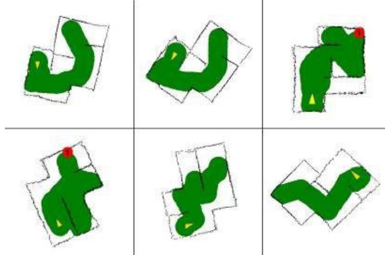
We are done with LASER based SLAM and also we've added gyro sensors for keeping laser horizontally when robot is moving over the step-fields and ramps. Figure 3 shows sample maps generated by our autonomous robot just by processing Laser scanner data. The mapping is based on PCM.
6. Sensors for Navigation and Localization
Right at the moment, we use LASER scanner data for localization as well as for map generation. Gyro sensor does very important thing on Silver (our red arena robot) and also Avril (our yellow arena robot) which is keeping laser horizontally that we can use data of laser when the robot is going up and down. Green parts in Figure 3, shows the estimated position of the robot in arena exploration. Yellow triangle is starting points of mission, and red circle is place of victim. This estimation is just based on LASER scanner data. To detect roll and pitch angles, we take advantage of MEMS sensors.
7. Sensors for Victim Identification
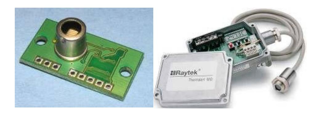
Our main sensor for victim identification is heat sensor. We use a pyrometer and 8 TPA81 Thermal arrays (see Figure 4). Another project which is now on the progress is using vision for victim identification.
8. Robot Locomotion
Our Famous tele-operated red arena robot "Silver" was well introduced in 2005 and 2006 description papers. This structure is debugged and we have designed and manufactured a new robot called "Silver2009". This robot is larger and has more powerful actuators. Silver2009 and Silver2005 could be seen in Figure 5.
The yellow arena robot is a four-wheeled robot. Fig6. Shows our autonomous robot named Avril.
Table 2 depicts Physical specifications of this robot.
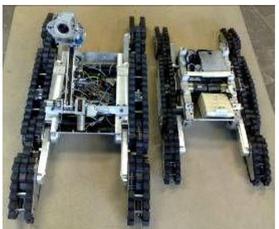
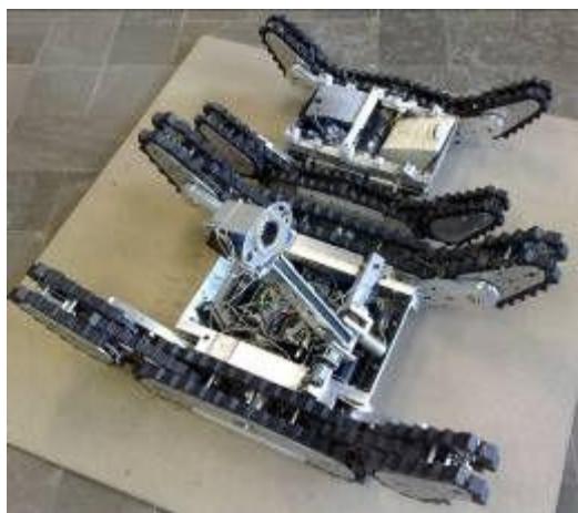
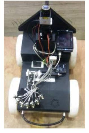
Table 2. Physical specifications of Autonomous robot
| Physical Specifications | ||
|---|---|---|
| Length | 50cm | |
| Width | 25cm | |
| Height | 30cm | |
| Turning Radius | 60cm | |
| Weight | 15kg | |
| Maximum Velocity | 23cm/s |
9. Other Mechanisms
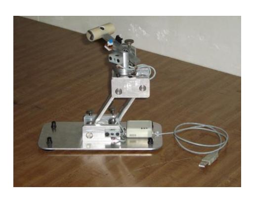
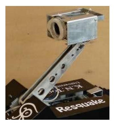
As it could be seen in figure 7, we have placed a manipulator on our robot that is mainly aimed for moving main camera to a desired position and orientation. The user interface without a specific device for controlling the manipulator makes it very difficult for the operator to control the system due to delays in system and separately setting the position and orientation of the manipulator just with the available video feedback. To solve this problem, we have decided to add almost the same manipulator structure near the operator. Operator can easily set the desired position and orientation of the camera by means of moving this special HMI device to a proper position and orientation. The hardware of this device is actually a copy of the manipulator which is currently installed on the robot. This device can help the operator to seek in the holes (The boxes that where added to red arena in RoboCup2006).
Dexterous Manipulation
As it could be seen in figure 7, we have placed a manipulator on our robot that is mainly aimed for moving main camera to a desired position and orientation. The user interface without a specific device for controlling the manipulator makes it very difficult for the operator to control the system due to delays in system and separately setting the position and orientation of the manipulator just with the available video feedback. To solve this problem, we have decided to add almost the same manipulator structure near the operator. Operator can easily set the desired position and orientation of the camera by means of moving this special HMI device to a proper position and orientation. The hardware of this device is actually a copy of the manipulator which is currently installed on the robot. This device can help the operator to seek in the holes (The boxes that where added to red arena in RoboCup2006).
Autonomous stair climbing
Stairs are important items in red arena missions. Silver is designed to be capable of ascending the stairs and it has been several times demonstrated to overcome this encounter in previous tele-operations. Despite this, there have been cases of failure in climbing, due to inadequate clues of robot state available from visual signals, which have led to tumble of the robot. This predicament invoked us to design a control system to enable the robot to surmount stairs autonomously. It should be noted that reducing operator driving responsibilities, speeds up the search and rescue mission and enables him to control several robots simultaneously.
The act of climbing stairs may be decomposed into following subroutines:
- Detecting stairs
- Making primary adjustments
- Climbing
- Landing
Among these subtasks, climbing is most important and challenging. In order to accomplish a successful climb, it is necessary to verify and eliminate the sources of instability.
It can be seen that if the robot is commanded a forward constant velocity on a set of stairs, it gradually drifts from straight heading angle until complete instability and tumble [3]. Therefore inappropriate heading angle is identified as a source of instability. Besides this, improper azimuth angle is recognized as another source of insecure climb.
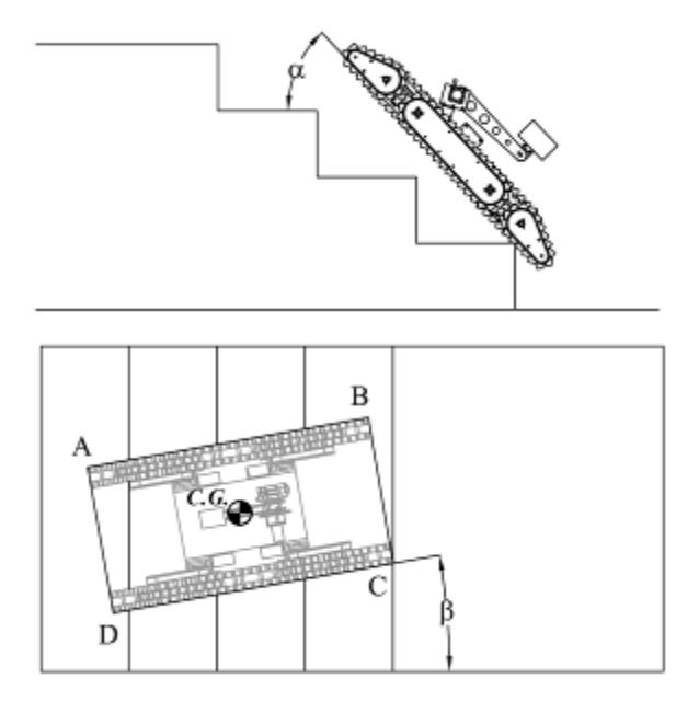
Statically, azimuth angle of robot should be controlled in order to keep image of center of mass on ABCD rectangle until the end of climbing (see figure 8). By taking the motion of robot into account, the azimuth acceleration of the robot plays an important role in instability of the robot.
We have begun with mathematical modeling the relation between the sources of instability and other parameters of the system. After validating this model, a proper control system should be designed to retain heading and azimuth angle within the safe margins during the climb.
Designed control system is then supplied with the azimuth and heading angle and is expected to produce proper control commands for the robot to climb the stairs, maintaining the secure heading and azimuth angle.
10. Team Training for Operation (Human Factors)
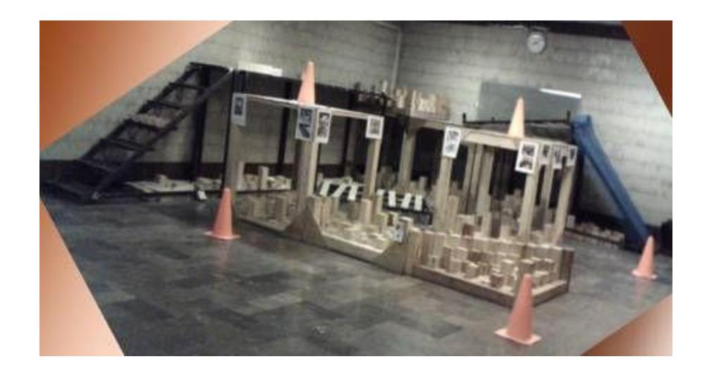
Resquake operator interface (winning the Best operator interface award in RoboCup2006-Bremen) is a very simple interface which needs almost zero training time. Almost everybody is familiar with pedal-throttle driving and everybody can talk to the robot using microphone. To train a professional operator, the operator of course needs practice time in real arena. We have made a small red arena (figure 9) having eight step fields, a couple of pallets, two staircases and ramps. The operator can practice in this area whenever the system is operational.
11. Possibility for Practical Application to Real Disaster Site
The tele-opereted robot is becoming close to the goal. It should be note that the communication system for the real mission should be something more reliable than typical 802.11 based wireless LANs. Real arena is not always the ideal dry RoboCup arena in normal temperature in a roofed building. These are all the challenges that should be taken to account for the real disaster.
12. System Cost
A separate red arena robot (Silver) costs less than 10 thousand US dollars. A separate yellow arena robot costs 6 thousand US dollars, but the overall system including a tele-operated and an autonomous robot costs less than 12 thousand US Dollars.
References
[1] www.fathsoft.com [2] www.msdn.microsoft.com [3] John D.Martens, Wyatts S.Newman,"Stabilization of a Mobile Robot Climbing Stairs", IEEE Intl. Conference on Robotics and Automation, pp.2501-2507