RoboCupRescue 2009 - Robot League Team SAE Robotique (Canada)
Simon St-Pierre
SAE Robotique Ecole Polytechnique de Montreal; Ecole Polytechnique of Montreal
Abstract This paper outlines SAE Robotique entry to the RoboCupRescue competition with L'Éclaireur, its first Urban Search And Rescue (USAR) Robot prototype. Team approach was to create a sturdy platform that will allow Sensor integration, Electronic and Software development in the next years while improving mechanical design.
Introduction
SAE Robotique is a group of students of the Ecole Polytechnique of Montreal. Its mission is to insure to future engineers a complement to their academic formation offering to them the unique chance to participate in a multidisciplinary project directly linked to the industrial reality. Our goal is to provide a work experience centered on practical work, the application of theoretical notions and to develop work group and interpersonal relations abilities. The work is voluntarily done by the students during their free time.
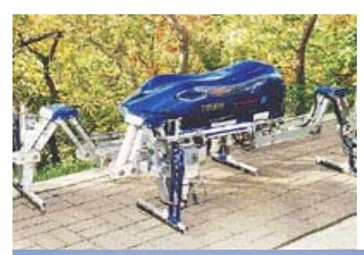
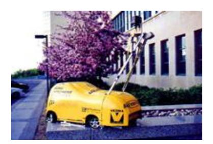
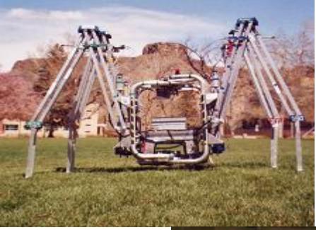
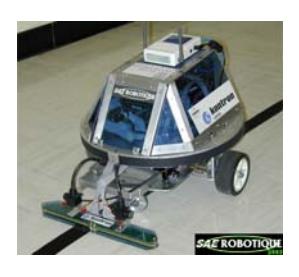
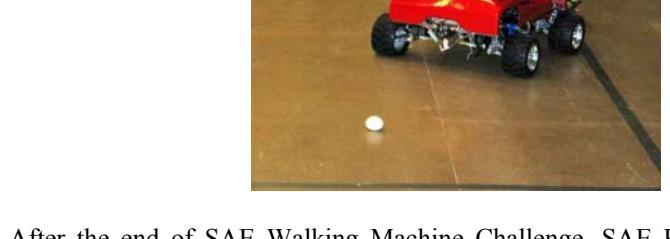
Created in 1991, SAE Robotique team originally intended to participate to the SAE Walking Machine Challenge. Over the years, different prototypes were built:
After the end of SAE Walking Machine Challenge, SAE Robotique decided in 2007 to design a USAR robot which has a concrete and humanitarian application. After two years of development SAE Robotic is proud to present its fist prototype: L'Éclaireur.
During the first year, the team designed the shape of the robot, its locomotion system, the robotic arm, electronic components and selected sensors and peripherals. The robot construction, assembly and programming took place in the second year.
In the next years, our goal will be to focus on Software development to generate a high precision map. Once this will be accomplished, Software development will move toward autonomous exploration and victim detection.
The mechanical team will continuously improve the main frame of the robot to allow greater speed and manoeuvrability. If major modifications to the robot are needed, a new prototype will be designed.

1. Team Members and Their Contributions
Simon St-Pierre Project Manager, Electrical Design (Power Distribution, Motor Control)
Pierre-Luc Bourgeois Mechanical Design (Drive Train, Propulsion, Front Arms )
Patrick Mutchmore Software Design (Platform, Device Drivers)
Alexandre Villeneuve Mechanical Design (Chassis, , Robotic Arm), Robot Assembly
Marc Blondin Mechanical Design (Robotic Arm Modifications)
Luan Luan Mechanical Design (Robotic Arm's Head Modifications)
David Laporte Software Design (Graphical User Interface)
Jérémie Galarneau Software Design (Device Drivers) Christian Babeux Software Design (Device Drivers) Alexandre Monette Software Design (Joystick Control) Etienne Bolduc Software Design (Map generation) Jonathan Ménard Electrical Design (Robotic Arm Control) Mehdi Mahmoudi Electrical Design (Robotic Arm Control)
2. Operator Station Set-up and Break-Down (10 minutes)
- Set-Up
- Boot-Up Robot Computer
- Boot-Up Operator Station Computer
- o Connect Printer
- o Connect Joystick
- o Launch Server, GUI and other programs
- o Launch Client on the robot (via SSH)
- If robot is still on AC/DC Power Supply, disconnect it to run only on battery.
- Bring the robot to the starting point
- Power-Up all robot's peripheral.
- Break-Down
- Power-Down all robot's peripheral.
- Shutdown robot computer (via SSH)
- Shutdown Operator Station Computer
- Disconnect Printer and Joystick from Operator Station Computer
3. Communications
ROBOT
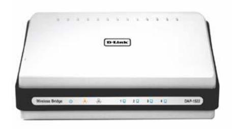
- D-Link® Xtreme N™ Duo Wireless Bridge/Access Point (DAP-1522)
OPERATOR STATION COMPUTER
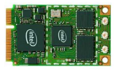
- Intel® Wireless WiFi Link 4965AGN
We will use the DAP-1522 to generate a simple wireless network. Three setup in the 5 Ghz band are possible: 802.11a only, 802.11n only, or mixed 802.11n and 802.11a. Further tests are needed to determine which offers the best range/bandwidth ratio.
Another DAP-1522 might be used instead of the 4965AGN on the operator station computer if a bridge configuration offers better performance.

Rescue Robot League - SAE Robotique (Canada) Frequency and Power Settings
| Rescue Robot League | Frequency | Channel/Band | Power (mW) |
|---|---|---|---|
| SAE Robotique (Canada) | 5.0 GHz - 802.11a | ||
| 5.0 GHz - 802.11n |
4. Control Method and Human-Robot Interface
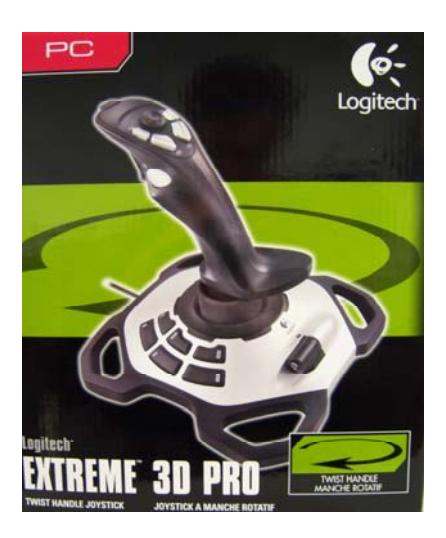
The robot will be manually controlled via the Logitech® Extreme™ 3D Pro Joystick. It has a USB interface.
Joystick controls include:
- Steering
- Front arm rotation
- Robotic arm movement
- Power ON/OFF/AUTO of the lighting system
Autonomous Behavior:
- Victim Detection:
- o Temperature level warning
- o CO2 level waning
- Ambient light detection and lighting system power ON/OFF
Mouse control:
- Victim Detection:
- o Validate if voice or sound was head
- o Validate if movement was seen on the video camera
- o Select victim state
- o Select victim situation
- o Video print screen of the victim (tag identification)
- Map generation
- o Manual modification of map if needed
- o Manual victim localization on map if needed
- Other:
- o Tab selection
- o Map Zoom
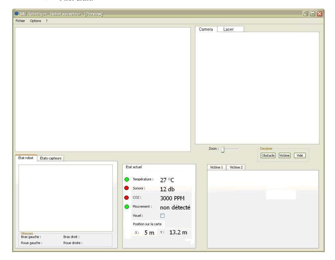
Graphical User Interface
- Map visualization (top left)
- Real-time video stream (top right tab)
- Real-time laser view (top right tab)
- 3-D view of robot tilt & front arms position (Bottom left tab)
- Overview of all sensors (Bottom left tab)
- Victim detection related sensors state (Bottom center)
- Confirmed Victim information (Bottom right, New tab created for each victim)
- First draft:
5. Map generation/printing
The map generation is based on the Simultaneous Localization And Mapping algorithm (SLAM). More specifically, we are using the FastSLAM algorithm[1].
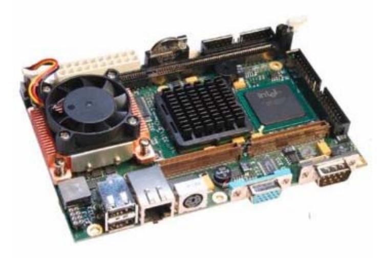
The computer of the robot, a JRex-PM form Kontron will be used only for data acquisition and Sensor/Motor control.
All Data will be transferred to the Operator Station Computer to be analysed, i.e. map calculation and generation will be made on the Operator Station Computer. This allows for minimum requirement / power consumption on the robot computer and permit maximal computer processing on the Station Computer since it has no limitation.
Data input:
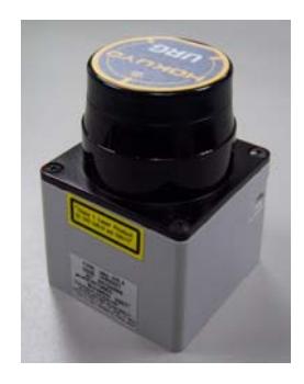
Hokuyo's URG-04LX
- o Detectable range is 20mm to 4000mm
- o 100msec/scan
- o 240° area scanning range with 0.36° angular resolution
- o USB interface
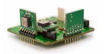
Sparkfun's 6DOF v2
- o Three gyro readings from 3 ADXRS300
- o Three tilt readings from the tripe axis accelerometer MMA7260Q
- o Serial TTL interface
Motor encoder
- o Provide robot speed
- o Provide robot traveled distance
Manual modifications of map if needed:
- Add/Remove obstacles
- Correct position of victims
6. Sensors for Navigation and Localization
Navigation:
To help manual navigation, the Logitech® QuickCam® Communicate STX™ will provide a video feed. It has a USB interface.
Also, if the laser range finder detects an obstacle to close to the robot, the operator will be warned in the GUI. Similarly, if the accelerometer measures a critical tilt angle of the robot, the operator will be warn to make sure he will not flip the robot upside-down.
Localization: See section 5: Map generation.

7. Sensors for Victim Identification
Please use this section to describe the sensors you use for victim navigation [tactile, acoustic, ultrasonic, infrared, visual, laser, chemical, encoder, other], and explain how you use them.
Movement & Form Detection
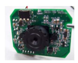
The Logitech® QuickCam® Communicate STX™ will be used to detect movement and human body form.
C02 Detection
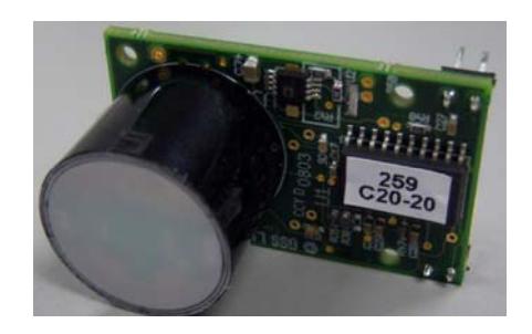
The Miniature Optical (NDIR) Carbon Dioxyde CO2 Sensor form AIR MONITORS Ltd. will be used to detect CO2 level. It has a serial TTL interface.
Body Heat Detection
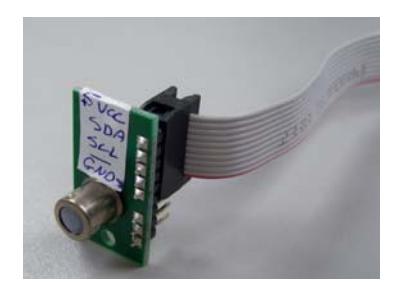
The 8 Pixel Thermal Array Sensor form Devantech Ltd. will be used to detect body heat.
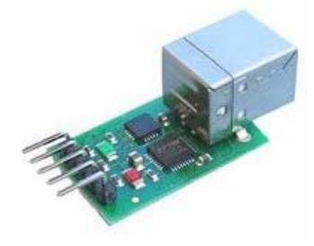
The I2C output of the sensor will be connected to the Devantech Ltd. USB to I2C Interface Module to be interpreted directly on the computer.
Sound Detection
The microphone on the Logitech® QuickCam® Communicate STX™ will be used to detect different sounds. It will be placed in a cylindrical tube to enhance the range (faint moaning up to 10 meters) and limit the robot noise capitation that will cover the sound of interest.
8. Robot Locomotion
Main Frame:
Dimensions (aluminium chassis + track width):
o Length : 24"
o Width : 25"
o Height : 8"
o Length totally deployed: 33"
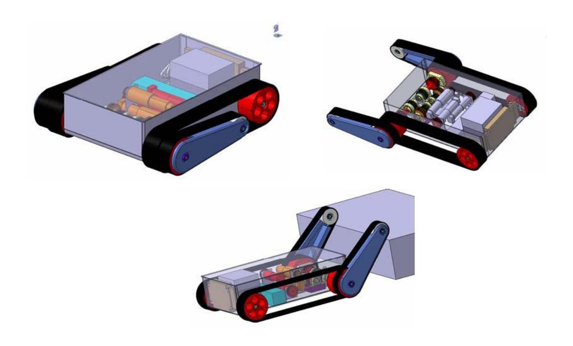
4 tracks system
o 2 for the differential steering,
- o 2 for the front arms.
Propulsion:
- 4 Maxon motor : RE 40 Ø40 mm, Graphite Brushes, 150 Watt. (148867)
- 4 Encoders HEDS 5540, 500 Counts per turn, 3 Channels (110513)
- Gearhead:
- o 2 Planetary Gearhead GP 42 C Ø42 mm, 3 15 Nm, 113:1 (203126) for the propulsion
- o 2 Planetary Gearhead GP 52 C Ø52 mm, 4 30 Nm, 257:1 (223102) for the front arms independent rotation.
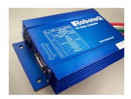
- 2 Roboteq AX-2850 Dual axis 120A motor controllers
9. Other Mechanisms
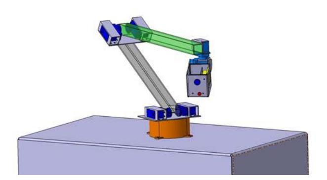
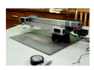
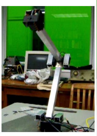
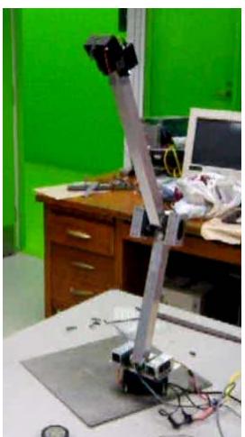
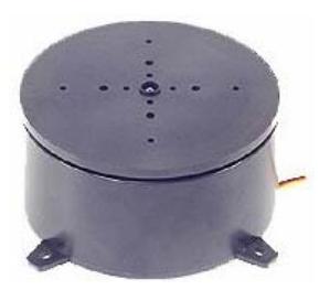
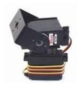
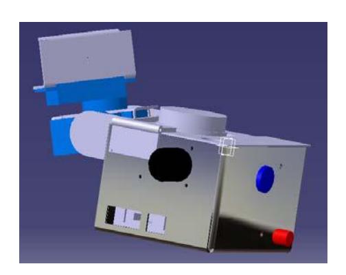
A 5 degrees of liberty robotic arm will be used to look in hard to reach areas :
First prototype:
10. Team Training for Operation (Human Factors)
Please use this section to describe what kind of training is required to use your system, and what kind of skills are beneficial for operators of your system. Also, how you went about training your team members for the competition.
- GUI Training:
- Learn basic functions and victim confirmation
- Learn warnings & appropriate response
- Learn map related functions
- Robot Control Training:
- Learn mix control of the robot steering / robotic arm movement with the joystick.
- Lean other robot functions
- < 10 minute start-up sequence training
11. Possibility for Practical Application to Real Disaster Site
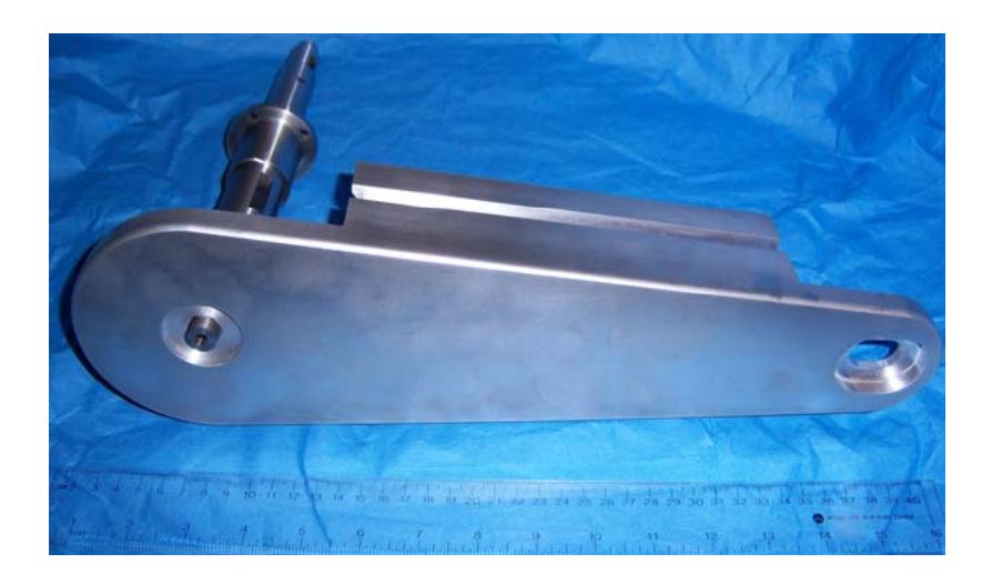
Our robot is design for sturdiness and obstacle crossing. All calculations were done with a security factor of 2. All robot mechanical components are in aluminium; chassis, transmission and drive-train parts had a core thermal treatment.
12. System Cost
All listed price are in $CAN, taxes & shipping included.
System Cost - Sensors, Peripherals & Components
| Part | Quantity | Unit price | Total Price |
|---|---|---|---|
| AIR MONITORS Ltd. Miniature CO2 Sensor | 1 | 500,00 $ | 500,00 $ |
| Devantech Ltd. Thermal Array Sensor | 1 | 130,00 $ | 130,00 $ |
| Devantech Ltd. USB to I2C Interface Module | 1 | 55,00 $ | 55,00 $ |
| Lighting System | 1 | 300,00 $ | 300,00 $ |
| Speaker- communication System | 1 | 100,00 $ | 100,00 $ |
| Hokuyo URG-04LX | 1 | 3 300,00 $ | 3 300,00 $ |
| Roboteq AX-2850 | 2 | 920,00 $ | 1 840,00 $ |
| Sparkfun 6DOF v2 | 1 | 431,25 $ | 431,25 $ |
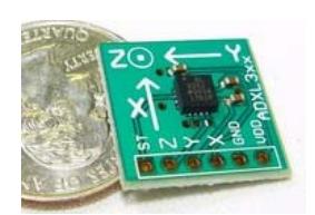
| Sparkfun's breakout board 2 axis ADXL320 | 1 | 45,00 $ | 45,00 $ |
| Logitech® QuickCam® Communicate STX™ | 1 | 100,00 $ | 100,00 $ |
| Robot Power Distribution | 1 | 1 000,00 $ | 1 000,00 $ |
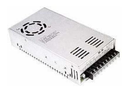
| Mean Well S-350-24 PSU | 2 | 51,00 $ | 102,00 $ |
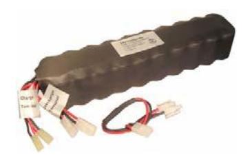
| Battery 24V 10Ah | 2 | 375,00 $ | 750,00 $ |
| Electronic components | - | - | 500,00 $ |
| Printed circuit fabrication | - | - | 300,00 $ |
| Total Sensors, Peripherals & Components | 9 453,25 $ |
System Cost - Control & Communication
| Part | Quantity | Unit price | Total Price |
|---|---|---|---|
| D-Link® Xtreme N™ (DAP-1522) | 1 | 120,00 $ | 120,00 $ |
| Kontron JRex-PM | 1 | 800,00 $ | 800,00 $ |
| Logitech® Extreme™ 3D Pro | 1 | 60,00 $ | 60,00 $ |
| Total Control & Communication | 980,00 $ |
System Cost - Mechanical Components & Machining
| Part | Quantity | Unit price | Total Price |
|---|---|---|---|
| Unmachined raw material | - | - | 300,00 $ |
| Front arm and Drive train machining | - | - | 7 000,00 $ |
| Chassis machining | - | - | 400,00 $ |
| Drive train gears, ball bearings & pulley | - | - | 1 200,00 $ |
| Robot Tracks & wheels | - | - | 1 613,08 $ |
| Motor + gear heads + encoders | 4 | 1 000,00 $ | 4 000,00 $ |
| Robotic arm raw material | - | - | 150,00 $ |
| Lynxmotion Base Rotate Kit | 1 | 28,00 $ | 28,00 $ |
| Hitec HS-645MG | 1 | 52,00 $ | 52,00 $ |
| Hitec HSR-5980SG | 4 | 165,00 $ | 660,00 $ |
| Lynxmotion Pan and Tilt Kit | 1 | 56,00 $ | 56,00 $ |
| Robotic arm's Head machining | - | - | 200,00 $ |
| Special Tooling | - | - | 215,00 $ |
| Total Mechanical components & machining | 15 874,08 $ |
Robot cost: 26 307,33 $CAN
References
[1] Thrun, S., Burgard, W., Fox, D.,: Probabilistic Robotics. The MIT Press, (2006), 647p.