RoboCupRescue 2009 - Robot League Team SAVIOUR (Pakistan)
Wardah Inam, Muneeb Zia, Nasreen Shayeq, Khwaja Umar, Khurram Aziz, Muhammad Fahd
Ghullam Ishaq Institute of Engineering Science and Technology Topi 23640, Swabi, Pakistan
Abstract In this paper, we have introduced our first competitive rescue robot. It is track based, with two sets of independent flippers. It is semi-autonomous, requiring one human operator, and is designed to aid the operator during decision making. This is not a commercial product, but meant to demonstrate how much capability can be achieved for extremely low costs.
Introduction
SAVIOUR (Semi Autonomous Vehicle for Inspection, Observation and Ultimate Rescue) is a robot capable of traversing and mapping a complex and unknown terrain. The impetus was the October earthquake in the northern areas of Pakistan, and how many lives could have been saved had such a robot been easily available to the rescue teams then.
It has a low CG design for maximum stability. It has leveraging capabilities using two sets of independent flippers to climb over obstacles.
It requires one operator; however, the operator is aided in the driving decisions by the robot. All the other functionality is fully automatic i.e. all the sensing.The operator will make the final call wherever needed, e.g. in the detection of victims, or when overriding a safety braking mechanism etc.
1. Team Members and Their Contributions
Please use this section to recognize all team members and their technical contributions. Also note your advisors and sponsors, if you choose.
Team Members and Their Contributions
| • | Dr. M. Junaid Mughal (Faculty of Electronics Engineering) | Advisor | |
| • | Dr. S. A. Bazaz (Faculty of Electronics Engineering ) | Advisor | |
| • | Dr. Naseer Ahmed | (Faculty of Mechanical Engineering) | Advisor |
Khurram Aziz - Mechanical Design
Muhammad Fahd - Communication
Wardah Inam - Team Leader & Electronics
Muneeb Zia - Electronics & Control
Nasreen Shayeq - Mapping and Software
Khwaja Umar - Mechanical Design
2. Operator Station Set-up and Break-Down (10 minutes)
One person from the team will be in charge of the station set-up and breakdown. Station set-up includes.
- Laptop set-up
- Wireless communication set-up
- Testing of components
3. Communications
Most of the processing of all kinds will be done at the base station. All communication to the robot is entirely wireless.
a. Data to be transmitted:
Motor(s) control
Camera control
b. Data to be received:
Sensor data
Video Streams
Other observatory data (if infra-red, etc.)
The robot communicates with the base station, and vice versa, as a specialized Wireless LAN network. At the receiving end are microcontrollers that need to be provided logic levels to function. They are sent over a standard wireless connection. We are using a TP-Link TL-WA601G Wireless Access point and are also using a router to multiply the number of available Ethernet side interfaces. The switch used is a Baynet BN-1708K 8 Port Nway Switch. This is a standard 8 port switch.
Our system uses a communication frequency of 2.4GHz, and adheres to 802.11g standards.
Rescue Robot League - SAVIOUR (Pakistan) Communication Specifications
| Rescue Robot League | ||||
|---|---|---|---|---|
| SAVIOUR (Pakistan) | ||||
| Frequency | Channel/Band | Power (mW) | ||
| 2.4 GHz - 802.11b/g | Any | - | ||
| 1.2 GHz - Video Transmitter | - | - | ||
| 900 MHz - Video Transmitter | - | - |
There is no wireless internal communication of the components. Each module is a self dependent system serviced via the external wireless service.
4. Control Method and Human-Robot Interface
SAVIOUR is being navigated remotely by the operating station via keyboard and joystick. The control of the robot is being achieved by two AT89C51 microcontrollers. The first is responsible for controlling the locomotion of the robot by generating appropriate PWM while the second is interfaced with different sensors (ultra-sonic, IR etc) for victim detection and obstacle avoidance.
4.1 Command Center
- Laptop and joystick
- Human Computer Interface
4.2 GUI
Graphical user interface is designed to aid in the navigation of the robot and victim detection. It is underdevelopment.
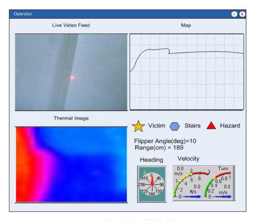
Live Video Feed
The video will be from the wireless camera. The operator will be monitoring the live feed and adding details to the map e.g. Victim detected
Map being generated
Map will be generated on basis of simple rangefinder program.
Thermal Image
Thermal image obtained from the thermal sensors in conjunction with the camera image.
Information from other sensors
Other sensor information will also be displayed. E.g. Digital compass, tilt sensor etc.
5. Map generation/printing
Map generation method in our semi-autonomous robot (SAVIOUR) is based on the operator assessment in conjunction with the collected data and a GUI program, which enables operator to locate and register different object such as victims, stairs, walls and hazards. The robot is installed with laser, wireless camera, ultrasonic sensors, thermal sensors, digital compass, tilt sensor and other sensors to provide enough information to operator station.
The laser and camera will be used to find the range. A laser-beam will be projected onto an object in the field of view of a camera. This laser beam is parallel to the optical axis of the camera. The dot from the laser is captured along with the rest of the scene by the camera. A simple algorithm is run over the image looking for the brightest pixels. Laser is the brightest area of the scene, the dots position in the image frame is known. Then we need to calculate the range to the object based on where along the y axis of the image this laser dot falls. The closer to the center of the image, the farther away the object is.
6. Sensors for Navigation and Localization
This section covers all navigation and localization sensors used in SAVIOUR.
6.1 Ultrasonic Sensors
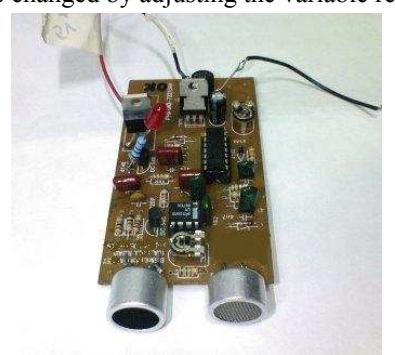
40 kHz ultrasonic sensors are being used for obstacle avoidance. Any obstacle within 0.3m of the robot triggers the sensors to give a high pulse which overrides the operator control momentarily. Four of these have been placed on the sides of the robot. This range can manually be changed by adjusting the variable resistors.
6.2 IR distance sensor
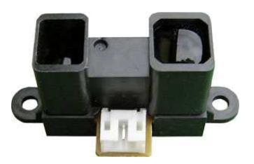
IR range finder is used along with laser data to generate the map. The Sharp GP2Y0A02YK infrared ranger is able to continuously measure the distance to an object. The usable range is 20 cm to 150 cm. The device generates an analog voltage that is a function of range, and the output voltage can be measured by an analog-todigital (ADC) input line.
6.3 Cameras
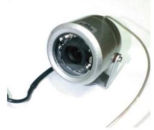
Two cameras are being used
- Front Night vision camera
This is the primary camera being used for map generation and victim detection.
- Rear Camera
This camera has been place at the rear of the robot to have a greater view of the surroundings
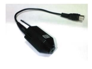
6.4 Tilt sensing
An accelerometer is being used to sense the tilt of the robot. This data is fused with data of the camera for accurate map generation.
6.5 Position and Orientation
An optical mouse sensor will be used for position and localization. This sensor communicates via synchronous serial and will give the x and y positions.
The optical and compass sensors will be used to continuously update the robot's position and orientation for mapping and navigation purposes
6.6 Tachometer
The speed of the two primary motors is being measured. The data is being compared so that they are revolving at the same speed. This data also helps in the map generation.
7. Sensors for Victim Identification
This section covers all sensors used for detecting and identifying victims.
7.1 Microphone
An electric microphone is being used for victim detection. Sound processing is done on the base station which prompts the user if a victim is detected. The audio data will be transmitted back to the user via the same wireless transmitter that is used to transmit the video feed.
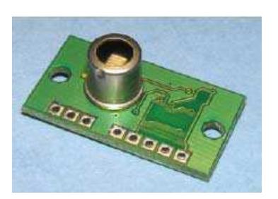
7.2 Thermal sensors
Thermal sensors are being used to detect victims autonomously by their body heat. Servos move the sensors to create a 2D image. Thermal image is created with colors depending on the temperature values. The sensors data is sent to the base station where this image is created.
7.3 Motion detection
The front low light camera is being used to capture the video. Video processing is done on the base station to detect any motion.
8. Robot Locomotion
This section describes the mechanical locomotion systems of SAVIOUR.
8.1 General Description
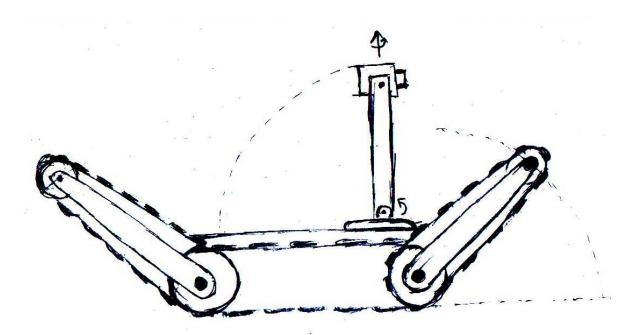
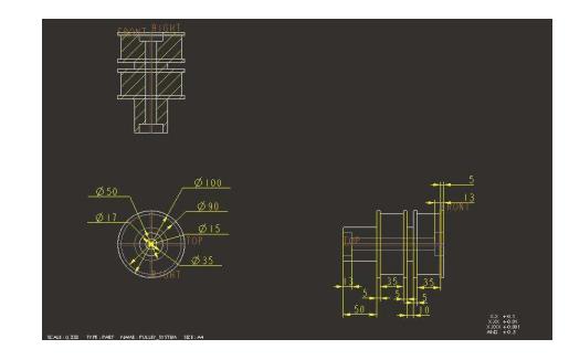
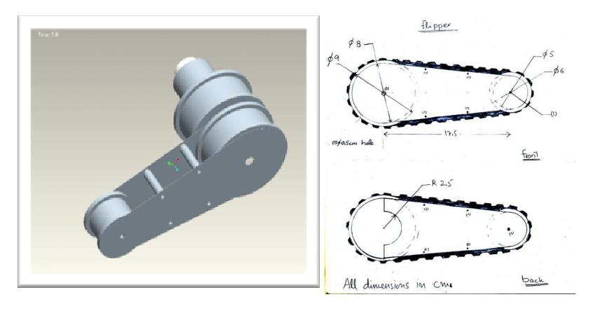
The robot runs on rubber tracks, a total of six that will be controlled by 2 motors; one motor for each side. Robot uses a total of four flippers, two at front and two at rear. Front and rear flippers have separate lowering and raising mechanisms. So a total of 4 motors are required for the locomotion of the robot, one each for the front and rear flipper's lowering and raising mechanism and one each for the rubber tracks on the left and right side of the robot.
In addition to this, couple of servos will do for the camera mount providing 360° view as well as tilting mechanism. The camera can be lowered to accommodate in the base while entering spaces with little vertical clearance or chances of rollover. Camera mount will be discussed in detail later.
8.2 Tracks
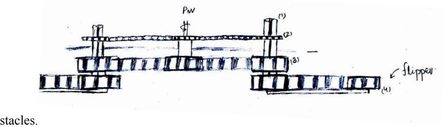
The tracks being used for the robot are rubber tracks. The rubber tracks that we are using are such that they have an interface with the ground ensuring maximum grip which is needed for climbing the ramps, stairs and other ob-
8.3 Camera Mount
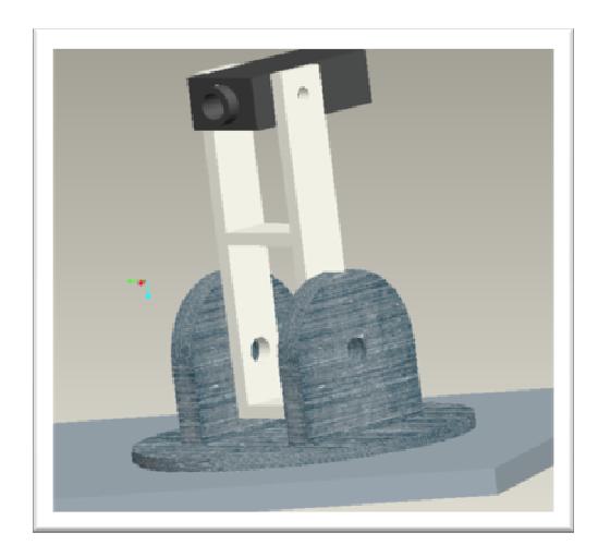
To mount the camera, laser and other sensory devices, a camera mount has been provided, that requires two motors. This mechanism allows for 360° rotation along the z-axis (axis perpendicular to the ground) and 180° rotation on the axis parallel to the ground. The motor that will be used for the full 360° rotation is a stepper motor. The 180° rotation is provided by a servo motor by rotating form -90° – 0° – 90° . The advantage of this mechanism is that it provides us with same maneuverability as in any other mechanism, but with less no. of motors. We can lower the camera using this mechanism to allow the robot to travel through places with low vertical clearance.
8.4 Center of Gravity
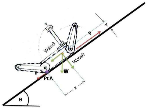
The robot will have to have low center of gravity to ensure that it does not encounter any situation that will cause the robot to roll over. The highest risk of roll over lies in climbing the stairs. Let us calculate the position of Center of gravity of the robot that will prevent the rollover state.
8.5 Motors
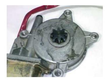
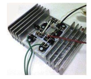
Main tracks are being driven by power window motors. Servo mechanism is being employed for the thermal imaging. Stepper motors with high resolution are being used for the rotation of laser and camera.
8.6 Power Window Motors
High torque is needed to pull SAVIOUR through the extreme terrain that it is intended to travel. The rotational speed is low. It has instant braking ability. It contains gears so no external gears are needed. Also they are affordable.
8.7 Stepper motors
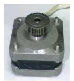
Laser and the camera are mounted on the stepper motor with step angle of 1.8 Deg ± 5°
9. System Cost
System cost breakdown for SAVIOUR robot.
System Cost Breakdown
| Cost Component | Amount (Rs.) |
|---|---|
| Total Electronics Cost | 84,100 |
| Total Mechanical Cost | 17,000 |
| Total Machining and Processing Cost | 11,000 |
| Total Processing Costs | 27,000 |
| Additional Miscellaneous Costs | 50,000 |
| Total Costs | 1,89,100 |
References
- Baker M., Casey R., Keyes B, and Yanco H. A. Improved Interfaces for Human-Robot Interaction in Urban Search and Rescue, University of Massachusetts Lowell
- Ozkan MS., Aydin CM. and Ozdemir A. Position Detection Using Ultrasonic Sensors, 2004
- Köhler M., Patel SN., Summet JW., Stuntebeck EP. and Abowd GD. TrackSense: Infrastructure Free Precise Indoor Positioning Using Projected Patterns, Institute for Pervasive Computing, Department of Computer Science ETH Zurich, 8092 Zurich, Switzerland