RRT Uppsala Team Description for RoboCup Rescue 2009
Alexander Nordfelth, Cristobal Wetzig, Martin Persson, Per Hamrin, Robin Kuivinen, Per Falk, Björn Lundgren
Department of Information Technology, Uppsala Universitet, Box 337, SE-751 05 Uppsala, Sweden
Abstract This document describes the autonomous robot team RRT Uppsala and its contribution to RoboCup Rescue, Graz, Austria 2009. The robot team consists of two different robot platforms. Along with these, the team provides a portable unit for map generation that can be used by other robots. The system performs rescue missions in a fully autonomous manner. Some of the more innovative features are the layer based map drawing, advanced AI, laser scanner, simultaneous localization and mapping (SLAM) and robot collaboration. The robots also use advanced image analysis using built-in cameras. System management is conducted via a user-friendly GUI where the operator can monitor and take control over the robots when needed. Keywords: Robocup, Rescue, Robot, Autonomous
Introduction
Team RRT Uppsala's contribution to RoboCup 2009 consists of two different robot platforms. Both platforms are fully autonomous and will share similar roles in a rescue mission. Cooperation is greatly emphasized; the portable communication and collaboration protocol and the advanced AI will divide the tasks between the robots.
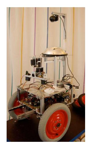
The system handles loss of communication and will reestablish collaboration when communication is up and running again. The robots Rym and Surt are based on last year's Sigrun1 design. The robot Loke is based on a platform that was introduced in the RoboCupRescue League of Suzhou, China 2008. The team has also developed a "mapping-box" which consists of a laser-scanner tower and a processing platform.
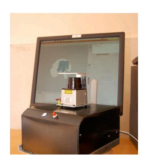
The mapping box has an easy to use interface and the aim is that the mapping box will be lent to other teams to be installed on for example an operator controlled robot that can traverse parts of the arena that our robots are unable to access. The unit can be used to generate a map of high quality.
The team consists of seven final year M.Sc. students (out of which four will be on site in Graz) and four advisors with different areas of expertise. The team is also working together with other University staff. The students are taking a summer course as a follow up to a larger project course that took place in the spring of 2009. The students have previously participated in RoboCup German Open in Hannover 20-24 april 2009. Uppsala University has a long history of participating in RoboCup Middle Size Soccer League, from 2000 to 2003 and in Rescue Robot League since 2004.
1 Team members and project roles
In the following Table, we list the team members and their roles in the project. We also list the senior advisors that are involved in the project.
Team members and project roles
| No. | Name (surname first) | Project Role | |
|---|---|---|---|
| Teachers | |||
| 1 | Larzon, Lars-Åke | [email protected] | Course head teacher |
| 2 | Rensfelt, Olof | [email protected] | Systems design |
| resource teacher | |||
| 3 | Åhman, Alexander | [email protected] | Hardware resource |
| teacher | |||
| 4 | Selig, Bettina | [email protected] | Image analysis |
| resource teacher | |||
| Students | |||
| 5 | Alexander Nordfelth | [email protected] | Chief software |
| m | architect | ||
| 6 | Christobal Wetzig | [email protected] | Image analysis |
| analyst | |||
| 7 | Per Falk | [email protected] | Systems |
| architecture analyst | |||
| 8 | Björn Lundgren | [email protected] | Microcontroller |
| analyst | |||
| 9 | Robin Kuivinen * | [email protected] | Systems |
| administrator | |||
| 10 | Per Hamrin * | [email protected] | Mapping analyst |
| 11 | Martin Persson * | [email protected] | Public relations |
= Will not be participating in Robocup, Graz
2 Operator station set-up and breakdown (10 minutes)
The entire robot system is easily set up due to the robots' simple onepiece construction.
Loke is a lightweight robot that is easy to transport. Rym and Surt are slightly heavier, but set-up is conducted in the same way as for the smaller robots. Since the robots are fully autonomous, the operator station does not need to be manned during operation. However, it is possible to control the robot system manually if desired. We are working towards the goal to have a line-up with at least two robots in every operation.
To manage the robots, the operator only needs access to a computer with a wireless 802.11a connection and the robot interaction software installed. All robots will be monitored by one computer only.
3 Communications
The robot system uses the IEEE 802.11a standard for wireless communication between the robots and the operator station and also among the robots. UDP is used for streaming audio and video to the GUI. For the internal communication between the sensor's microcontrollers and the main processor, a CAN-bus is used.
The system can either use ad-hoc or base station mode with multicast for more efficient transmission to several nodes without redundancy. The portable communication and collaboration protocol will be easy to implement on another robot, which makes the collaboration between robots a lot easier. In case of communication failure the robots can continue to operate by themselves until the communication has been reestablished. This limits the risk of wasting time or losing information.
Table of desired communication channels
| Rescue Robot League | ||
|---|---|---|
| RRT Uppsala University (Sweden) | ||
| Frequency | Channel | Power (mW) |
| 5.0 GHz – 802.11a | 36/Low (Primary) | 40 |
| 40/Low | ||
| 44/Low | ||
| 48/Low |
4 Control method and human-robot interface
Since the robot system works in a fully autonomous manner, no interaction is needed for a search mission except for the set-up of the system. However, it is possible to take control over the robots via a GUI when desired. The main purpose of the control interface is to monitor the robot progress.
Important information is sent to the control interface from the robots whenever a communication channel is available. This information is presented in the GUI on the operator station in the form of video feeds, sensor displays etc. If manual control of the system is desired, one operator can control all the robots simultaneously.
5 Map generation/printing
The robots share the map data between them allowing them to cooperate in building a complete map of the operating area. This map is collected by the operator station for visualization and modification in the GUI. The GUI can draw the map in different layers depending on which robot mapped which area. This will make tracking of how different robots map different areas easy. From the GUI it is possible to export the map in the GeoTIFF format and print the final map with a portable printer connected to the operator station.
In order to navigate safely and accurately in the environment the robots will use a modified version of the Monte Carlo localization algorithm in order to do SLAM. This will generate an accurate map and determine the robot position.
6 Sensors for navigation and localization
All sensors are connected to the robot's central computer through a CAN bus or USB.
Laser range scanner
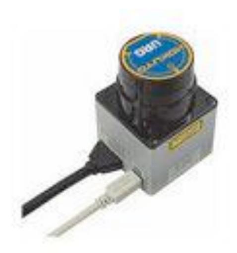
All robots use a movable laser scanner to scan the terrain. In its original format, the scanner has a horizontal coverage of 240°. The laser scanner makes it possible to determine the position of the robot, based on the generated map. For these functions a SLAM algorithm is implemented. The laser is also used to detect rubble (stepperfields) in the arena.
Ultrasonic sensors
Ultrasonic sensors complement the laser scanner. They are primarily used to detect obstacles around the robot. They can prevent the robot from colliding with walls and obstacles as it is turning or going in reverse. A front-mounted, down-facing sensor is also used to detect gaps in the floor in front of the robot to prevent it from going over an edge that is too steep.
Camera
The camera mounted on the robots is used, in addition to victim identification, to detect areas of the arena that the robot should avoid.
Surt also features a second webcam pointed at an omni-directional mirror. That camera will be used to detect warning signs for hazardous materials.
Gyro sensors/accelerometers
The robots are equipped with a gyro sensing x- and y-relative movements. The gyros are used to detect slopes and inclines in the area which will yield a more accurate map. The gyros also provide input to servo-motors that stabilize the sensor towers.
7 Sensors for victim identification
Rym and surt use the same sets of sensors for the purpose of victim identification. These sensors are connected to the rest of the system in the same manner as the localization sensors.
Thermopile arrays
A heat sensitive camera with eight pixels capable of measuring absolute temperature values of its surroundings is used to identify victims. By measuring temperature and comparing the reading to the ambient temperature accurate identification of victims is possible. The sensors are mounted in the front of the robot and oscillate 180 degrees. By measuring the angle at which a heat indication is found and triangulating a direction, the victim can be found. By sweeping the heat sensor we can also produce a heatmap of the area around the robot.
Camera
A camera is mounted in the front of each robot and it is used for taking snapshots of found victims. The camera can also be used to detect motion. The camera has a LED spotlight fitted to produce better images in dark environments. The front facing camera can also be used to send a video feed to the operator.
Microphone and speaker
The robots are equipped with a built in microphone and speaker that will be used to communicate with victims. Rescue personnel will be able to talk to the victim to get an early estimate of their condition.
8 Robot propulsion
All robots support rotation around their own axis, are wheel based and also compensate for sloping ground.
Rym and Surt
Rym and Surt are designed with two engines that drive the front wheels independently of each other. They do also have a third passive rear wheel. This gives the robots the possibility to rotate 360 degrees around their own axis.
Loke
This robot is designed with two engines driving two wheels on each side independently. This gives the robot the ability to rotate 360 degrees around its own axis. The four wheel drive system also gives the robots good maneuverability even though they are rather small.
9 Team training for operation (Human factors)
Since the system is fully autonomous and a user-friendly GUI is provided, very little previous knowledge is required for operating the system. The only knowledge needed from the operators is fundamental knowledge of the displays in the GUI.
The simulation software USARSim is used for training the robot operators and performing testing of the robot software. A training environment have been used on site in Uppsala, with stepper fields and obstacles built according to the specification of the competition rules, in order to achieve a competition like experience.
10 Mapping box
The team has developed a small and mobile platform for performing synchronized localization and mapping (SLAM) using a laser scanner. The mapping box can easily be connected to a host robot via a USBbus or TCP/IP. The box is designed to be small enough to be attached to the back of a robot using mounting screws or strong adhesive.
Usage of the mapping box is meant to be entirely transparent to the host robot. The host robot may send information about its movements to the mapping box in order to improve map generation accuracy although this is not a requirement.
11 Possibility for practical application to real disaster site
Since the system is fully autonomous and relatively cheap in production, it would be possible to distribute a large amount of robots over a vast disaster area to be able to cover it more quickly. These types of robots can be used to conduct reconnaissance actions in disaster sites where it is dangerous to send in human personnel. Our system for scanning the terrain and even victim identification could be very useful in realistic disaster sites. However, the current design may be cost efficient but is still completely unshielded against fire, and may therefore need to be made more rugged should it be used in a real scenario.
12 System cost
See appendix 1 for details. Rym and surt cost per each approximately 4763€. Loke cost approximately 2806€. The Mapping Box cost approximately 2342€.
Observe that the approximate cost does not include the cost for operator workstation and network router.
Appendix 1 – System costs
Since robot development is still in progress, the following list is an estimation.
System costs for Rym and Surt (per each)
| No of items | Module | Approx. cost (€) |
|---|---|---|
| CPU components | ||
| 1 | Hectronic H6015 PC/104+ CPU | 220 |
| 1 | Hectronic H7006 CANcard PC/104+ | 39 |
| 1 | Compact Flash PCMCIA Adapter | 22 |
| 1 | Compact Flash 2GB Memory Card | 25 |
| 1 | D-Link 7-port powered USB Hub | 22 |
| 1 | D-Link Wireless USB Adapter | 37 |
| 1 | PCMCIA USB 2.0 Adapter | 13 |
| Propulsion | ||
| 2 | Maxon RE40 DC Motor | 264 |
| 2 | Motor controller cards (Custom made) | 236 |
| 2 | Planetary gear | 234 |
| 1 | Rear wheel | 30 |
| 2 | Front wheel | 31 |
| Sensors | ||
| 1 | Hokuyo URG-LX04 Laser Scanner | 1800 |
| 4 | Devantech TPA 81 Thermopile array | 312 |
| 2 | Logitech E1000 Webcam | 100 |
| 1 | Omnidirectional Mirror | 24 |
| 1 | Directional microphone | 15 |
| 1 | LIS302DL Sparkfun Accelerometer | 13 |
| Microcontrollers etc. | ||
| 3 | Integrated AVR, CAN and optocoupler circuitry | 84 |
| 1 | Assorted electronics (LED:s, switches) | 30 |
| 1 | Electronic Assembley 16x4 LCD Display | 25 |
| Assembly | ||
| 1 | Custom framework assembly and material | 825 |
| 1 | Assorted mounting brackets and screws | 60 |
| 1 | Assorted cabling and connectors | 50 |
| 4 | HITEC HS322 Servo Motor | 120 |
| Power | ||
| 2 | Milwaukee 12V rechargeable battery | 112 |
| 1 | Charger | 25 |
| Total: | 4763 |
System cost for Loke
| No of items | Module | Approx cost (€) |
|---|---|---|
| 1 | VIA EPIA ML 6000EAG Fanless Motherboard | 92 |
| 1 | D-Link WLAN Card, DWL-AG530 (PCI) | 78 |
| 1 | Compact Flash 2GB Memory Card | 25 |
| 1 | CF2IDE Adapter (CF Reader) | 7 |
| 1 | PC2100 266MHz 512MB RAM Memory | 52 |
| 1 | Compact Flash 2GB Memory Card | 25 |
| 1 | CAN-USB interface | 30 |
| Propulsion | ||
| 2 | 7,2V 100oz-in. DC Gearhead Motor | 51 |
| 1 | Motor controller card (Custom made) | 118 |
| 2 | Chains for power transmission | 25 |
| 2 | Geolanders tire pair | 20 |
| 2 | F5 Wheel pair | 17 |
| 2 | Axeltrees - Hex hub pair | 13 |
| Sensors | ||
| 1 | Hokuyo URG-LX04 Laser Scanner | 1800 |
| 1 | Logitech E1000 Webcam | 50 |
| 1 | LIS302DL Sparkfun Accelerometer | 13 |
| 1 | Integrated AVR, CAN and optocoupler circuitry | 28 |
| 1 | Assorted electronics (LED:s, switches) | 10 |
| Assembly | ||
| 1 | Chassis - Lynxmotion 4WD1 Chassis Only Kit | 59 |
| 1 | Custom framework assembly and material | 50 |
| 1 | Assorted mounting brackets and screws | 20 |
| 1 | Assorted cabling and connectors | 20 |
| 2 | HITEC HS322 Servo Motor | 60 |
| Power | ||
| 1 | picoPSU-60 WI 6-26V DC-DC ATX PSU | 60 |
| 2 | Battery | 58 |
| 1 | Charger | 25 |
| Total: | 2806 |
System cost for Mapping box
| No of items | Module | Approx cost (€) |
|---|---|---|
| 1 | VIA EPIA ML 6000EAG Fanless Motherboard | 92 |
| 1 | D-Link WLAN Card, DWL-AG530 (PCI) | 78 |
| 1 | Compact Flash 2GB Memory Card | 25 |
| 1 | CF2IDE Adapter (Compact Flash Reader) | 7 |
| 1 | PC2100 266MHz 512MB RAM Memory | 52 |
| 1 | Compact Flash 2GB Memory Card | 25 |
| Sensors | ||
| 1 | Hokuyo URG-LX04 Laser Scanner | 1800 |
| Assembly | ||
| 1 | Custom framework assembly and material | 30 |
| 1 | Assorted mounting brackets and screws | 15 |
| 1 | Assorted cabling and connectors | 15 |
| 2 | HITEC HS322 Servo Motor | 60 |
| Power | ||
| 1 | picoPSU-60 WI 6-26V DC-DC ATX PSU | 60 |
| 2 | Battery | 58 |
| 1 | Charger | 25 |
| Total: | 2342 |
References
- CAN-bus: http://www.kvaser.com/can/
- GeoTIFF: http://www.remotesensing.org/geotiff/geotiff.html
- Monte Carlo Localization: http://www.cc.gatech.edu/ai/robot-lab/onlinepublications/dellaert_frank_1999_2.pdf