RoboCupRescue 2010 - Robot League Team Team CASualty (Australia)
Adam Milstein, Matthew McGill, Claude Sammut, Rudino Salleh, Reza Farid, Jaime Valls Miro, Gamini Dissanayake, Mohammad Norouzi
ARC Centre of Excellence for Autonomous Systems, School of Computer Science and Engineering, University of New South Wales; ARC Centre of Excellence for Autonomous Systems School of Electrical, Mechanical and Mechatronic Systems University of Technology, Sydney Broadway NSW 2007 Australia
Abstract This document describes the "Team CASualty" entry into the 2010 RoboCup Rescue competition. Our 2010 entry builds on our previous four entries (2005, where we came third overall, 2006, where we made the semi-finals in the main competition and came second in the autonomous competition, 2007, where we reached the finals, and 2009 where we achieved best in class autonomy). This year we are focusing on autonomous traversal with victim identification as well as 3d mapping and position tracking, including map synthesis between multiple robots. We will be bringing thre robots, one based on the iRobot Negotiator, the other based on the iRobot Packbot and the other a four wheeled robot. We will demonstrate multi-robot 3D SLAM for unstructured environments as well as autonomous victim identification.
Introduction
Team CASualty represents the ARC Centre of Excellence in Autonomous Systems (CAS), which is a collaboration between the Australian Centre for Field Robotics at the University of Sydney, the Artificial Intelligence Research Group in the School of Computer Science and Engineering at the University of New South Wales and the Mechatronics and Intelligent Systems Group at the University of Technology, Sydney. Team CASualty has had considerable success in past competitions, coming third in 2005; reaching the semi-finals in 2006, where we also came second in the auton-
omy competition, reaching the finals in 2007, and coming first in the autonomous challenge and second in the mobility challenge in 2009.
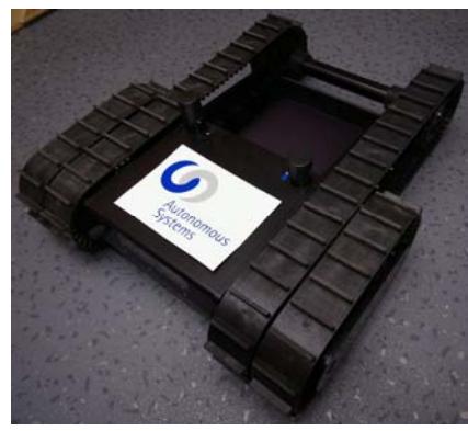
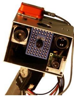
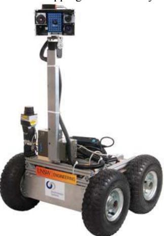
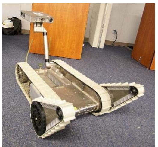
The robot team currently consists of three primary vehicles (Figures 1, 2 and 3):
Negotiator: Using the iRobot Negotiator as a base, we have added additional sensing and computational capabilities that permit either teleoperation or autonomous operation.
Emu: A 4 wheeled robot base that has less mobility than the Negotiator but is more stable for mapping and autonomy
Packbot: An iRobot PackBot Explorer has been equipped with an additional sensor head package and external computer power.
In addition to our mobile platforms, Team CASualty makes use of a variety of advanced sensors for mapping and victim identification, as well as highly effective, integrated user interfaces for multi-robot control and map building. This year we also intend to demonstrate autonomous victim identification in the yellow arena.
1. Team Members and Their Contributions
Please use this section to recognize all team members and their technical contributions. Also note your advisors and sponsors, if you choose.
• Adam Milstein SLAM and autonomy
• Matthew McGill Software architecture and victim identification
• Rudino Salleh Hardware and mechanical design • Claude Sammut Advisor, strategy, planning • Timmothy Wiley Autonomous victim identification
• Reza Farid Feature identification for mapping and victim id
• Gamini Dissanayake Advisor, strategy, planning
• Jaime Valls Miro Software integration, navigation, SLAM • Mohammad Norouzi Software and hardware architecture, controls
• Further student members are likely to join the team
2. Operator Station Set-up and Break-Down (10 minutes)
Our equipment deployment arrangements currently consist of:
- Negotiator , Emu and Packbot robots, all powered on and in idle state, waiting on a trolley.
- An 802.11a (5GHz) access point. The robots connect to this automatically once it is activated.
- Two portable laptop computers that have all software already configured.
- A portable battery-powered printer for producing maps and victim photographs.
- An emergency radio controller in case the wireless network fails.
This is similar to our setup for 2009 where the set-up and break-down times were around 6 minutes. However, this year we hope to create a unified operator station where a single container holds the laptops and access point in a user ready state, requiring only to be transported to the deployment location by a single person and opened. This should provide a significant improvement to our deployment time, which in the past has suffered slightly from the need to connect, power, and place the access point.
3. Communications
As in previous years, Team CASualty will be using a combined 802.11a/b/g wireless LAN access point for primary communications. This access point can be configured to only operate in 802.11a (5GHz) mode and can be channel locked. Being unsatisfied with our particular choice of access point in previous years, in 2010 we will be using a Planet Networking and Communications WDAP-2000PE Super A+G WLAN Managed Access Point with PoE. Our tests with a sample model have indicated that this device provides superior performance.
We also have the capability to use Bluetooth communications to control our robots. This mechanism is useful to manually drive from place to place without interfering with other teams use of the 802.11a/b/g frequencies.
Rescue Robot League - CASualty (Australia) - Communications Specifications
| Rescue Robot League | ||
|---|---|---|
| CASualty (Australia) | ||
| Frequency | Channel/Band | Power (mW) |
| 5.0 GHz - 802.11a | 802.11a channels |
17dBm @54Mbps |
| (as directed) | 20dBm @6Mbps | |
| ~(100mW) | ||
| 2.4 GHz - Bluetooth | spread-spectrum | 10mW |
4. Control Method and Human-Robot Interface
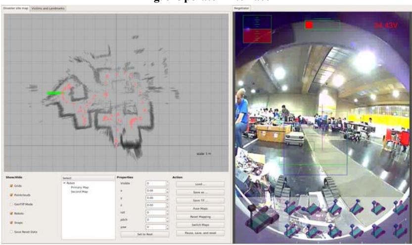
Our user interface builds on our previous entries [2], which allowed a single operator to control multiple robots. The operator may use a keyboard and mouse control scheme to manually drive the robot based on the output from its sensors, especially the wide angle camera. The operator also has the option to superimpose the various other sensors, such as the thermal, zoom, or depth cameras, on the image in the correct locations. This allows the operator to obtain more information about particular views, such as those containing victims, while not overwhelming him with extraneous data while merely driving the robot from place to place.
The interface also allows the user to either control the position of the head manually, or to select from amongst several presets. The current and desired positions can of course be observed from the screen. The flippers on the negotiator robot are handled using the same mechanism. The pitch and rotation of the sensor head can be controlled by selecting a point in the image with the mouse, which causes the head to attempt to centre on that point, bringing all of its cameras to bear. Of course, this can only be achieved within the mechanical capabilities of the sensor arm, which can be estimated from the display.
As well as manual control, the operator can enable and disable various autonomous operations, such as bump and go or wall following, at any time. These options include fully autonomous mode with victim identification, which may also be enabled or disabled at any time. When in autonomous victim identification mode the robot operates independently, alerting the operator to potential victims by displaying the images of the proposed victim, allowing the operator to confirm or reject it. Afterwards, the robot continues its autonomous path.
The other panel of the interface displays the current map and allows the operator to perform operations such as labelling victims, modifying current victims, and manipulating the map itself. This panel also allows the operator to restart the robot after a software crash by reloading the state from an up to date log file.
5. Map generation/printing
One of the difficulties with operating the rescue robot remotely is that it is sometimes difficult for the operator to determine the position of the robot. It is also difficult to understand the layout of the problem area given only the robot's sensor data. We use a SLAM (Simultaneous Localization and Mapping) [6] algorithm which maintains the robot's position and simultaneously develops a map of the environment which has been observed. The operator will be able to control the robot with reference to its position in this map and will also be able to use the map in order to plan the robot's activities.
SLAM is a difficult problem in the Robocup Rescue environment because the estimate of the robot's motion, which is usually obtained from the wheel encoders, is highly inaccurate on a non-regular surface. We use a scan matching algorithm between consecutive laser scans for simple odometry. This gives us an accurate enough position estimate that standard algorithms for SLAM can be used. We intend to use a similar algorithm with a rotating laser for 3 dimensional position tracking .
Based on our tracking algorithm, we use an implementation of FastSLAM for occupancy grid maps to correct the robot's position and update the map. By using an occupancy grid map containing height information for each cell, we maintain a three dimensional map of the environment sufficient to represent a single level. This map provides the estimated sensor readings required by FastSLAM while allowing the necessary map updates to be performed efficiently. When 3 dimensional position tracking is available, this map will be augmented with additional height data to provide a true 3D map with multiple levels.
By separating the position tracking algorithm from the rest of FastSLAM, we allow a distributed implementation. Since a SLAM solution often requires a significant amount of processing, this algorithm is performed on a remote machine, while position tracking is performed onboard the robot. Thus for short periods the robot can track its own position, while receiving periodic corrections from a base station when communications are available. This system further lends itself to allowing the robot to drive itself temporarily if operator control is not available.
Our FastSLAM algorithm generates an occupancy grid heightmap for each of a set of proposed paths for the robot. After the run is complete, we select the most probable path and apply a height and probability threshold to create a two dimensional occupancy grid. That map is encoded as a geotiff image, together with the various parameters necessary to relate the representation to the physical environment. The positions of the victims are also labeled in this image, along with the robot's path. We will also add a system for fusing the maps from separate robots into a single result.
6. Sensors for Navigation and Localization
Hokuyo URG-04LX Laser scanner: This lightweight (<200g) linescan LIDAR provides range data through a 220º scan in 0.3º increments at 10Hz, up to a distance of 4m. Its small size allows it to be mounted on an auto leveller servo system. This sensor is used for position tracking of the robot and for the FastSLAM algorithm. Because of the auto leveller we can only calculate two dimensional information from this sensor
Hokuyo UTM-30LX Laser scanner: This device is similar the URG-04LX except it has a range of 270º at 0.25° resolution with 30m range and scans at 40Hz. We intend to use servo motors to rotate this LIDAR so as to get a true three dimensional scan of the environment [3]. With this we will perform 3D position tracking and mapping. It will be used on 2 platforms.
CSEM SwissRanger SR3100: This range camera provides a 176x144 pixel range image at 30fps up to around 7m, based on time-of-flight. This information can be used to build a 3D point cloud that is very useful for mapping and overcomes many of the issues with simple 2D laser scanners. Although the data is often noisy it provides distance and shape information about the victims. It is used on all platforms.
Robot Arm: All platforms have a robot arm that allows the sensor package to be raised up to obtain a higher view. The sensors are mounted on pan-tile units that are used to obtain 360˚ panoramas, as well as directing attention to particular places.
Heading/attitude sensor: Both robots use Xsens MTI heading/attitude sensors. These sensors provide 3DOF orientation to a high degree of accuracy, assisting in automatic map generation and situational awareness. These sensors are also used to auto level the laser sensors.
Wide angle and long focus cameras: Both platforms use a variety of video cameras to obtain wide angle view for navigation and close-up views for inspection of objects.
7. Sensors for Victim Identification
ThermoVision Micron IR thermal camera: This lightweight, compact 160x124 pixel thermal infrared (7 – 14 micron) camera is a key component of the victim identification system. When calibrated with respect to the colour and range cameras, it is possible to localise heat sources very precisely within the Rescue arenas. Thermal imaging has the advantage of enabling victim identification in dark areas of the arena where the optical image is very poor, locating partially or completely occluded victims and adding to available victim information. Thermal information is also the first step in autonomous victim identification, since the temperature of a human body is relatively constant.
Thermoteknix Miricle IR thermal camera: This camera from Thermoteknix is fitted on the Packbot robot. It is slightly larger than the Micron, but has a high resolution 384x288 sensor in the 7-14 micron range. This camera forms the core of the autonomous victim identiffication system on Packbot.
Cameras: The optical cameras are an important component of the victim identification system. Both platforms are equipped with a number of colour cameras to allow them to identify victims including a long focal length camera, capable of better than 20:20 vision.
CSEM SwissRanger SR3100: By combining the depth information from this camera with its intensity information we can generate a monochrome image regardless of illumination. This allows us to identify victims in very dark areas, even if we cannot get the sensor head's light source close enough to provide illumination for the other cameras. We can also use the depth field data together with the other camera images to generate a coloured, 3 dimensional model of the victim.
Microphone: Microphones will be used to assist in the identification of the state of victims and provide additional information as to the robot's movements and surroundings. The sound from the microphones will be fed back to headphones worn by the operator or to speakers in the operator station.
8. Robot Locomotion
The Negotiator and Packbot robots are differentially steered vehicles with cleated rubber tracks. It also has tracked, driven arms mounted on the forward shoulders, allowing the robot to climb over obstacles of moderate size and to climb stairs.
Emu is a four wheeled differential drive robot that can traverse flat ground as well as moderate debris, although it cannot reliably traverse step fields or stairs. It can manoeuvre over tilted or discontinuous flooring and will be primarily used in the autonomous regions.
9. Other Mechanisms
One of the most important components of our entry is the software system which allows us to use identical software on both robots. This makes it easier for the operator to switch between control of the different machines. The software also allows various components to be enabled and disabled on the fly as the situation warrants. Thus our autonomous algorithms are not only used in the autonomous region, but can be used at any time to allow one robot to move while the operator is controlling the other. It also allows us to reassign tasks between the robots if necessary because of environment features or hardware problems.
10. Team Training for Operation (Human Factors)
Operator training for teleoperation of the robot team requires roughly a day of familiarisation with the controls although additional practice is expected to improve the operator's effectiveness. Training includes instruction on the nature of the robot platforms, the robots' articulation and robot arm, and the relative value of the data provided by each sensor. Our studies indicate that this approach is feasible and that operators with ten minutes of practice with the robot were able to learn enough to drive it around a simple maze [4]. As far as possible we have tried to use a similar interface to the standardised system in various computer games, so as to provide control with which many people already have experience.
11. Possibility for Practical Application to Real Disaster Site
The PackBot was designed for military use abd the Negotiator for law enforcement use, so it has been ruggedized for practical use. The sensor package and computers have been added by us and are not designed for extreme environments but are reasonably robust. Further engineering would be required for practical applications. The Emu robot is not robust enough for actual disaster deployment, but since our software system is not linked to any particular hardware, it is easy to apply it to any more rugged system.
12. System Cost
All amounts in US Dollars
KEY PART NAME: Negotiator
MANUFACTURER: iRobot (previously RoboticFX)
COST: $57,000
WEBSITE: http://www.irobot.com/sp.cfm?pageid=138 DESCRIPTION/TIPS: Tracked robot remote control/autonomous robot
KEY PART NAME: Volksbot MANUFACTURER: Fraunhofer IAIS
COST: $7,500
WEBSITE: http://www.volksbot.det
DESCRIPTION/TIPS: Four-wheel-drive robot remote control/autonomous robot
KEY PART NAME: PackBot Explorer
MANUFACTURER: iRobot COST: $135,000
DESCRIPTION: Tracked robot remote control/autonomous robot
KEY PART NAME: Laser rangefinder (x2)
PART NUMBER: URG-04LX MANUFACTURER: HOKUYO COST: $1,600
WEBSITE: http://www.hokuyo-aut.jp/products/urg/urg.htm DESCRIPTION/TIPS: Used to obtain accurate 2D range information.
KEY PART NAME: Laser rangefinder PART NUMBER: UTM-30LX MANUFACTURER: HOKUYO COST: $5,500
WEBSITE: http://www.hokuyo-aut.jp/02sensor/07scanner/utm_30lx.html DESCRIPTION/TIPS: Used to obtain accurate 3D range information when tilted.
KEY PART NAME: Camera PART NUMBER: Guppy F080C MANUFACTURER: AVT COST: $1,000
WEBSITE: http://www.canon.com/
KEY PART NAME: ThermoVision Micron IR Camera
MANUFACTURER: FLIR Systems COST: $13,000
WEBSITE: http://www.indigosystems.com/product/micron.html
DESCRIPTION/TIPS: Excellent detection of heat sources.
KEY PART NAME: Thermoteknix Miricle
PART NUMBER: KB
MANUFACTURER: Thermoteknix COST: $16000
WEBSITE: http://www.thermoteknix.co.uk
KEY PART NAME: MESA SwissRanger SR-3100
MANUFACTURER: MESA COST: $9,500
WEBSITE: http://www.swissranger.ch
KEY PART NAME: IMU PART NUMBER: MTi MANUFACTURER: XSens COST: $2,500
KEY PART NAME: Onboard Computer (x2)
PART NUMBER: UX92 MANUFACTURER: Sony COST: $3,200
KEY PART NAME: Onboard Computer
PART NUMBER: SBC-86860
MANUFACTURER: Esis COST: $1,500
References
[1] M. W. Kadous, R. K.-M. Sheh, and C. Sammut, "CASTER: A Robot for Urban Search and Rescue," in Proceedings of the 2005 Australasian Conference on Robotics and Automation, 2005. [2] M. W. Kadous, R. K.-M. Sheh, and C. Sammut, "Controlling Heterogeneous Semi-autonomous Rescue Robot Teams," in Proceedings IEEE Conference on Systems, Man and Cybernetics, Taiwan, 2006. [3] R. Sheh, N. Jamali, M. W. Kadous, and C. Sammut, "A Low-Cost, Compact, Lightweight 3D Range Sensor," in Proceedings Australian Conference on Robotics and Automation, Auckland, New Zealand, 2006. [4] M. W. Kadous, R. K.-M. Sheh, and C. Sammut, "Effective User Interface Design for Rescue Robotics," in Proceedings of Human Robot Interaction Conference, 2006. [5] R. Sheh, A. Milstein, M. McGill, R. Salleh, B. Hengst, C. Sammut, "Semi Autonomous Robots for RoboCup Rescue," in Proceedings Australian Conference on Robotics and Automation, Sydney, Australia, 2009. [6] M. W. M. G. Dissanayake, Paul Newman, Steven Clark, Hugh F. Durrant-Whyte, and M. Csorba, "A Solution to the Simultaneous Localization and Map Building (SLAM) Problem", IEEE Trans. on Robotics and Automation, Vol.17, No. 3, June 2001.