RoboCupRescue 2010 - Robot League Team PARS (IRAN)
Nima Enayati, Gholamhosein Mahaseni, Amirhosein Tamjidi, Mehdi Fallahinejad, Amir Mobarhani, Siavash Malektaji, Dr. Farid Najafi
PARS Robotic Group; KNTU
Abstract PARS Robotic Group has been introduced in IranOpen2006 competitions, where awarded the 4th place in real rescue robot league. Since then PARS robots have participated in many robotic competitions and have achieved considerable awards. We have designed and tested 2 new robots to gain better performance, reliability and robustness. Our new Tracked Tele-operated robot, Adora, with a special design providing smooth movement on rough areas and its specially designed communication system, has proved to be a reliable rescue robot. Robust communication system and a user-friendly interface help the operator to use the robots easily and perform various operations in a disaster area. Our new autonomous rescue robot, Nasir, implements many different algorithms in order to achieve a very real-time, concise and reliable map and navigates intelligently through the environment to detect victims.
1. Team Members and Their Contributions
• Nima Enayati Mechanical design / Team Leader
Gholamhosein Mahaseni Amirhosein tamjidi Mehdi Fallahinejad Amir Mobarhani Siavash Malektaji Dr. Farid Najafi Hardware Design Manufacturing Programming Communication Advisor
2. Operator Station Set-up and Break-Down (10 minutes)
Our operator interface consists of two laptops and a joystick. To operate the robots via internet from a far place, these equipments could be replaced with an internet connection, like a satellite station. These parts are packed in a backpack. One person should be able to carry this pack considering passing bumpy ways and climbing ladders. The system could be set up in few minutes, including opening up the pack, starting up robots and booting up the user interface program by a trained person.
3. Communications
Our Tele-operated robot's communication system is fully based on TCP/IP protocol. We use equipments supporting IEEE 802.11a standard to set up communication system which establishes the communication between the robots and operator station. We have also the ability to work in all three IEEE 802.11 standards (A. B.
and G ) and our communication devices have FCC certification, so we have not any kind of analog communication device or high power transmitter.
We have installed a dual band tri-standard (802.11a, b and g) "Wireless Router" (LINK-SYS WRT55AG) in the both robots (we can replace the router with a simple bridge with some additional changes, if we have restriction to use our own access point in the competition).
We haven't chosen any special channel, and we have the ability to set up our systems to work on any standard channel of 802.11a in few minutes even in the given time for preparing robots just before start the competition.
Rescue Robot League - PARS (IRAN) Communication Specifications
| Rescue Robot League | ||||||
|---|---|---|---|---|---|---|
| PARS (IRAN) | ||||||
| Frequency | Channel/Band | Power (mW) | ||||
| 5.0 GHz - 802.11a | Any available standard channel | 100 |
4. Control Method and Human-Robot Interface
There's only one operator who uses two laptops, one to control the Tele-operated robot and another to observe the Autonomous robot's condition. A combination of joystick, headset, keyboard and mouse is used to control the Tele-operated robot.
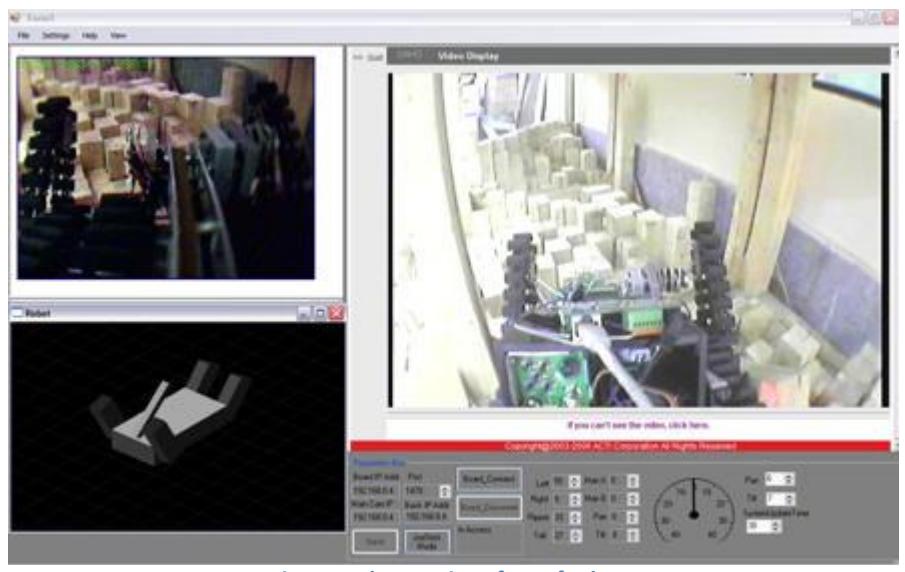
The Tele-operated robot's interface, which is depicted in figure1, is designed using Microsoft Visual C++ and DirectX SDK. The video streaming from two installed cameras can be observed. A 3D model shows the robot's condition (pitch, yaw, and roll data from a tilt sensor and the arms condition from two potentiometers). CO2 and heat sensor level indicators are located at the right bottom. The generated map will be shown by filling objects in 3D back mesh.
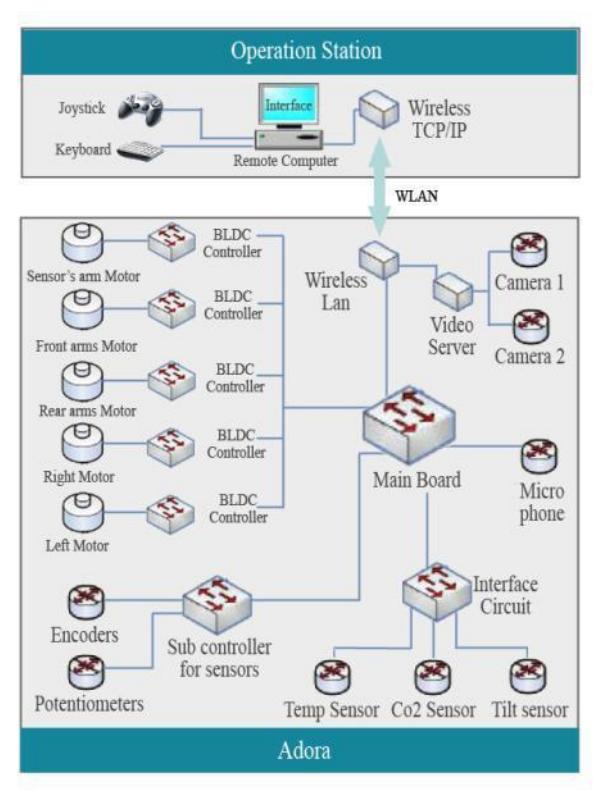
Figure 2 depicts the control structure of the Tele-operated robot, Adora. This control structure enables a highly responsive control by distributing the computation load of the total system among sub controllers.
5. Map generation/printing
We employ the GridSLAM method, a popular grid-based SLAM algorithm, to generate the map of the environment and simultaneously track the position of the robot in this map. GridSLAM takes the data from odometry and Laser Range Finder (LRF) sensors and uses the odometry and LRF data to establish the probabilistic motion and observation model of the robot. Application of GridSLAM extends the capability of the robot to autonomously navigate through an unknown area while making it possible for the robot to correct accumulative errors in localization and mapping when it visits the previously seen areas. The map generated by GridSLAM has another advantage as it is well suited for mapping of unstructured environments. In addition, there exist a great number of path planning algorithms that utilize the grid-based map of the robot surrounding as their input. For navigation purposes we also save and incrementally update the map of frontiers, which consists of the map of boundaries between known and unknown areas to the robot. Frontier map is used to determine sub goals for robot exploration and as the robot visits new areas the frontier map is updated and new boundaries are added to the map and explored boundaries are removed from the map until no unexplored area remains.
For our autonomous robot, Navigation algorithm is consisted of two sub-algorithms: first the algorithm for environment exploration, and second the algorithm for obstacle avoidance and reaching to a set point position. We use Frontier-Based exploration algorithm [2] to gain as much information as possible about the environment. This algorithm will determine where should the robot go in the next step and this set point is fed into the second sub-algorithm as a goal to reach while avoiding obstacles. For reaching to the determined set point we first employ the A* search algorithm to find a way through the obstacle free regions toward the representative point/points of the frontier chosen in previous step.
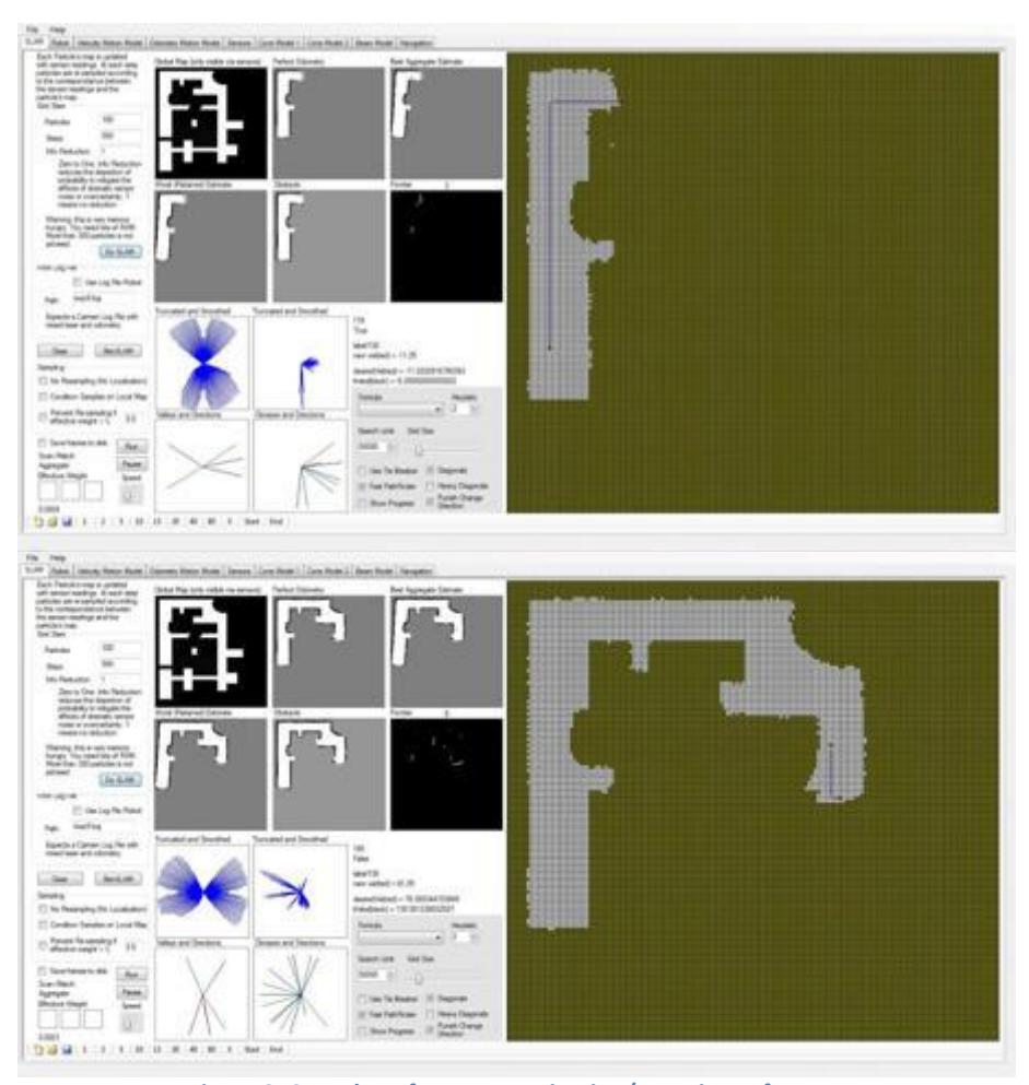
We have developed our mapping and navigation software based on Diversity GridSLAM code and added some classes and methods to the code in order to fulfill additional functionalities we need in our case. Screenshots from our navigation/mapping software are shown in figure 3.
6. Sensors for Navigation and Localization
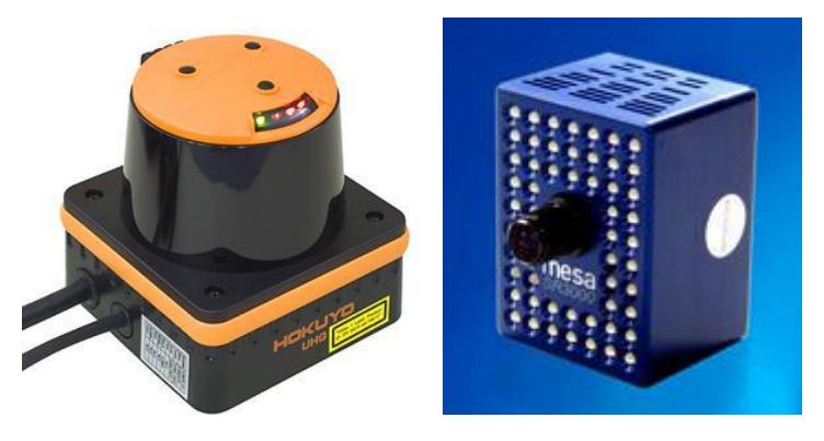
Main sensors for our autonomous robot's navigation and localization are URG-08LX Laser Range Finder, odometry and camera. Robot Navigation is assisted by a 1394 fire-wire camera which here helps the robot avoiding obstacles that are undetectable by LRF but can hinder the robot's mobility. Navigation is assisted by a SR-300 range camera which here helps the robot to avoid obstacles that are undetectable by LRF but can hinder the robot's mobility. In our Tele-operated robot the Navigation task is almost being done by the operator while he/she is assisted by the information from cameras and feedbacks from sensors mounted on the robot.
7. Sensors for Victim Identification
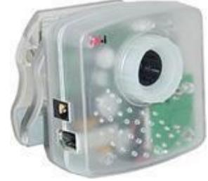
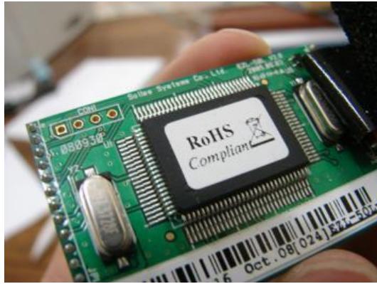
We mount two victim identification kits on our robots; one fixed kit comprised of CO2 sensor and camera, and one rotating kit comprised of microphone and an array of Thermopiles and PIRs. The CO2 sensor circuit uses a MG811 from HANWEI ELECTRONICS [2] which according to the manufacturer exhibits good sensitivity and selectivity to CO2 along with low humidity and temperature dependency. MG811, when exposed to CO2, produces an EMF inversely proportional to the concentration of carbon-dioxide. This voltage is digitized and transmitted to the pocket pc on board the robot (in autonomous robot) or the Laptop outside the arena (in Tele-operated robot) and appropriate decision is made about existence of victims based on it. Along with other sensors, each robot is equipped with a low-cost IEEE 1394 camera (figure 5) with a wide angle lens. We use video from this camera for identifying victims' tags and gestures.
The Microphone and the array of the Thermopiles and PIRs are placed on a revolving plate which rotates in a 180' arc around horizontal axes attached to the robot. The merit of such plate is that the robot can sweep more space for victim detection with fewer sensors. Microphone is used to detect the victim's sound and the SMT IR9902S thermopile and D203S PIR are used for measuring the environment's temperature and detecting the victims radiated heat respectively. SMT IR9902S is a non-contact sensor with high sensitivity and very good signal-to-noise ratio for measuring surface temperatures or Infrared radiation temperature on moving objects. D203S PIR is mostly used for motion detection and human body heat detection.
8. Robot Locomotion
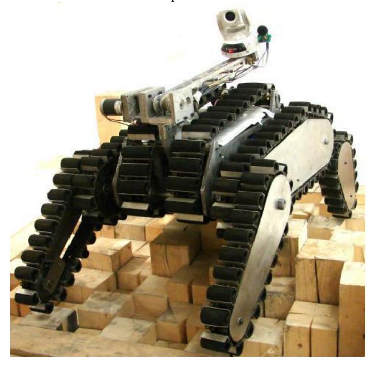
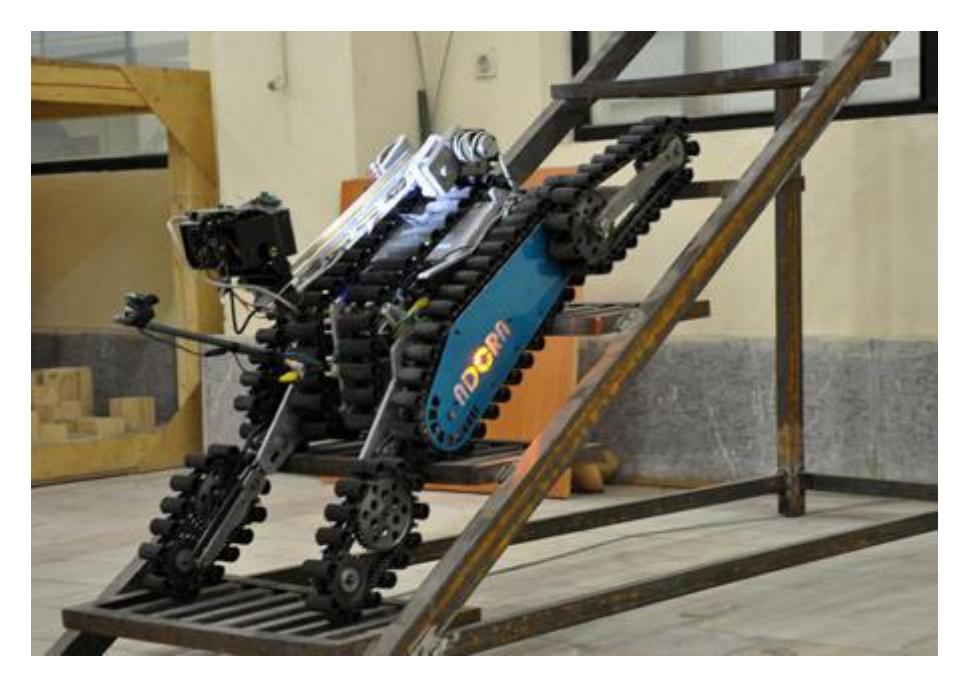
We had used rubber-belt tracks on two of our previous Tele-operated robots, PARS I and PARS II. These belts have some advantages like light weight and simple compose, but because of high amount of erosion, they have to be replaced after short periods of using robot on rough terrains. To rectify the infirm characteristic of rubber tracks on rough terrains we used a new traction system in our new Tele-operated robot, Adora. This new tracks are comprised of chains and plastic parts, which present high friction on common surfaces and drastic stress and tension strength. These tracks make this robot suitable for outdoor and harsh environment.
All parts of these tracks have been built from available and inexpensive materials from market.
Main and supplementary tracks are driven with two separate powerful 110W brushless DC motor. The heavy steel frame in previous robots is replaced with a precise main frame made of Aluminum plates.
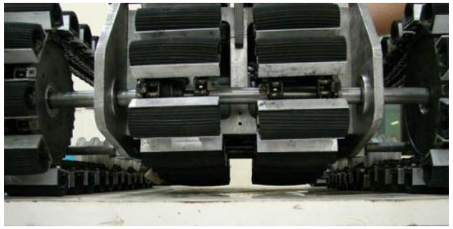
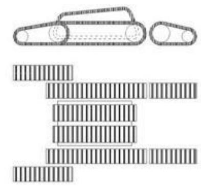
We have implemented a pair of supplementary tracks under the main frame to guarantee a continuous movement on uneven terrains, ensuring that obstacles under the robot won't hinder its mobility (Figure 6). To prevent extra friction force during centric rotation on flat surfaces, these tracks have a distance of 10 mm from the surface (Figure 7).
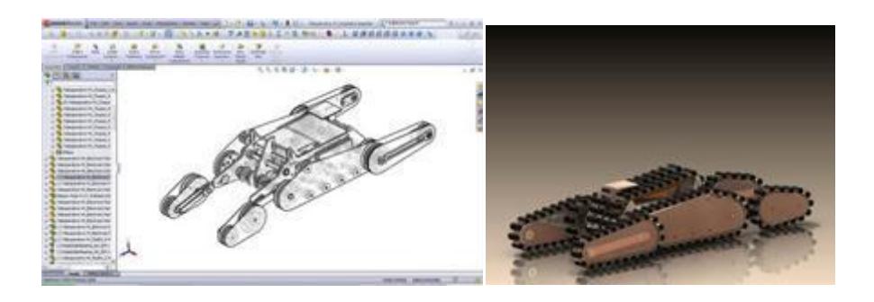
It should be mentioned that all the mechanical design process are carried out by our team using SolidWorks software (figures 8).
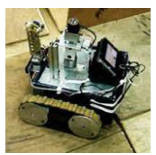
Locomotion of our autonomous robot is via two simple track belts (Figure 10).
9. Other Mechanisms
9.1. Robot Arms
In order to enhance maneuvering ability, a pair of front flippers has been widely used in explorer robots [4-5]. Front flippers help in climbing up stairs and extend the robot length for stepping over ditches.
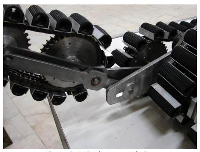
Based on preliminary models, an innovative design is proposed to satisfy all design requirements. As it is shown in Fig. 11, the conventional front pair of extended tracks can rotate 360 degrees, allowing the robot to climb over obstacles and stairs while a rear pair parallel to the main tracks provides additional traction and weight transfer. Thus while the rear arms will not hinder movement, the stability remains high.
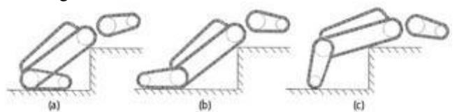
The robot also can climb bigger obstacles by using front flippers in reverse direction. Fig. 12 shows the procedure of climbing up obstacles from the robot rear. First, front flippers rotate to the rear to support the body, and then the robot moves toward the obstacle. When the body touches the obstacle, the front flippers rotate clockwise to raise the body and move the CG over the obstacle. This ability lets the robot to climb obstacles up to a height of 30 cm.
Rear arms are placed parallel to the side track, thus they should rotate around the rear wheels of the side tracks. To acquire this desired motion path, a 4-link slider mechanism is designed (Fig. 13).
9.2. Sensor Arm
At the time we are designing a 2 DOF Sensor arm for Adora. A pan and tilt camera and victim detection sensors will be mounted on this manipulator for advanced exploration in holes and detecting high elevated victims.
9.3. Communication module
We are using a hardwired TCP/IP chip (W3100 produced by WIZnet Co.) and a microprocessor for tele-operated robot to make a module converting usual types of data (in serial or parallel) to TCP/IP standard data so each of motor controllers, sensors, cameras and all other internal parts of the robot have a LAN interface for itself, and an IP address is assigned to.
This system has some advantages, adding new parts or replacing an existing part is so easy, also operator and other robots can set up connection with an internal part of the robot to command it or exchange data. In this project we just use IEEE 802.11a for any remote connection.
In addition, with this arrangement, it is possible to control robots from very long distance. It is just necessary to set up a small station to set up communication between disaster region and another point like a satellite.
10. Team Training for Operation (Human Factors)
As mentioned before our control software and user interface is more similar to a game environment than a hard operating program. So any person who has played 3D games with a PC by joystick and keyboard is ready to use the Tele-operated robot. Beside the main program there is a trainer that will guide new users step by step to learn how to control the robots. Besides, all of the team members are experienced enough to use the program and control the robots.
Table 1. Total System Cost
| key part name | part number | manufacturer | Cost($) | website | description/tips |
|---|---|---|---|---|---|
| 3D Camera | SR- 3000 | CSEM | 7000 | http://www.hokuyo-aut.jp/ | 3-D map building and navigation |
| Laser Range Finder | URG-08LX | Hokuyo | 4270 | http://www.hokuyo-aut.jp/ | localization and map building |
| Wireless router/Access point | WRT55AG | LINK-SYS | 200 | www.linksys.com | wireless communication (802.11a) |
| Communication module | - | Pars Robotic Group | 250 | www.parsrobot.com | LAN connection |
| BLDC Motor with driver | brushless 110Watt DC motor (4 Pcs.) | TWT | 350 | www.twt.com | moving mechanisms |
| Mechanical parts | - | Pars Robotic Group | 2500 | http://www.pars-robotic.ir | - |
| Non-contact thermometer | MT2 | Raytek | 80 | http://www.Raytek.ws | victim detection |
| PTZ camera | - | canon | 1000 | http://www.canon.com | Main camera (tele) |
| network camera | - | Gadspot | 170 | - | rear and front fix cameras |
| operator station | - | Pars Robotic Group | 2500 | http://www.parsrobo.org | - |
| camera | IEEE 1394 fire-wire | Unibrain | 151 | http://www.unibrain.com/ | Autonomous robot vision |
| CO2 sensor | MG811 | - | - | - | Victim detection |
| Thermopiles | SMT IR9902S | - | - | - | Victim detection |
| PIR | D203S | - | - | - | Victim detection |
| inclinometer | ADIS16209 | Analog Devices | 95 | http://www.analog.com | Mapping and navigation |
11. System Cost
Total system costs for most of the items used in the design are listed in table 1.
12. Lessons Learned
References
- Peter Biber and Wolfgang Straßer. The normal distributions transform:
- Yamauchi, B.: A frontier based approach for autonomous exploration. In: Proceedings of IEEE International Symposium on Computational Intelligence in Robotics and Automation, Monterey, CA, July 10-11, 1997. (1997)
- Shaghayegh Nazari, Shayesteh Kiaei, Amirhossein Tamjidi, Hamid D. Taghirad, Design and implementation of a concurrent mapping and navigation method based on Laser Range finder's data, (ICEE'9 -Iran)
- L. Matthies, Y. Xiong, R. Hogg, D. Zhu, A. Rankin, B. Kennedy, "A Portable, Autonomous, Urban Reconnaissance Robot," California Institute of Technology, Jet Propulsion Laboratory, Pasadena CA, 91109
- Jinguo Liu, Yuechao Wang, Shugen Ma, and Bin Li, "Analysis of Stairs-Climbing Ability for a Tracked Reconfigurable Modular Robot," IEEE Int. Workshop on Safety, Security and Rescue Robotics, pp. 36–41, June 2005.