Warwick Mobile Robotics – WMR (UK)
Dean O'Shea, Aleksa Starovic, Tom Astley, Paul Davis, Oliver Mulcahy, Oliver Batley, Matt Winterbottom, Adam Land, Micheal Tandy, Stefan Winkvist
University of Warwick United Kingdom – Engineering Department
Abstract Warwick Mobile Robotics (WMR) is an ongoing student research project for the Warwick Manufacturing Group (WMG). WMG is an institution within the University of Warwick, dedicated to improving organizational competitiveness through the application of technology innovation. Each year, the WMR team compete in the Robocup Rescue League, a global competition which tests robots' search and rescue abilities in a simulated disaster environment. Our group aims are to excel in all areas of the competition with a variety of features on our robot, moving towards a complete product for real world applications. Our main focus this year has been in improving on our predecessor tele-operated robot platform and making use of a new prototype Autonomous robot to test our SLAM mapping and autonomy.
1 Team members
| Dean O'Shea |
|---|
| Project manager, Mechanical |
| Oliver Batley |
| Mechanical, Solidworks Mechanical design, Implementation, Finance |
| Tom Astley |
| Mechanical, Design engineering, Composite materials |
| Aleksa Staroivc |
| Mechanical, Advanced robotics, Solidworks Mechanical design |
| Paul Davis |
| Manufacturing, Components testing, Solidworks Mechanical design, Sponsorship |
| Oliver Mulcahy |
| Electronic, Circuit electronics, Control logic, Programming, Electronic design |
| Matt Winterbottom |
| Electronic, Programming, Electronic design |
2 Tele-operated
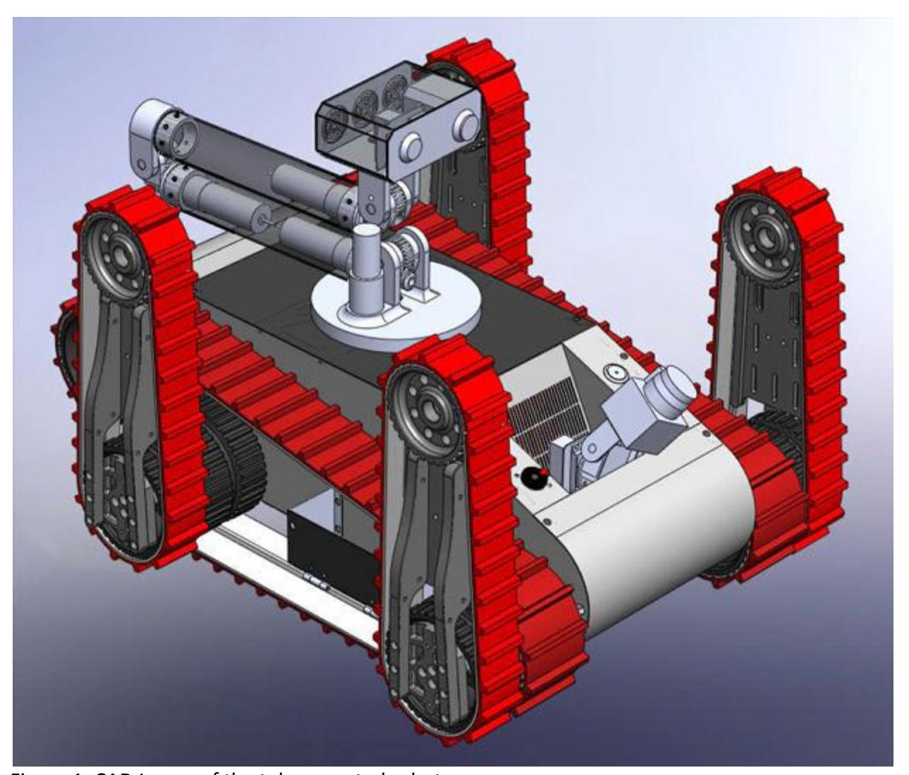
The tele-operated robot is designed for the sections of the competition that require good maneuverability over uneven terrain and steep slopes. In the previous year our robot won best in class for mobility in the German open and so much of the mechanical systems remained the same. Instead we focused on reducing the weight of the robot to obtain longer run times with the optimum battery configuration and also to aid in ascending the steeper slopes. We also installed new more suited motors to ensure optimum use of the tracks and flippers. Using large tracks and flippers it can negotiate obstacles to locate victims under the operation of a controller from a wireless position with no direct visibility of the robot. Every component has been modeled in Solidworks. This is essential for establishing the optimum configuration of components (from the positioning of electrical components and wires to the optimum fan cooling arrangement). It is also necessary for creating the CAD files used directly in the laser cutting process. A CAD image of this can be seen in figure 1.
Chassis
The tele-operated chassis is made from 6 panels. The side panels are made from 0.9mm laser cut steel. The top and bottom panels are made from 6-layer carbon fibre, made in-house. A main priority in the re-design of the tele-operated robot was weight reduction. Carbon fiber provides high strength to weight properties ideal for this application. This will offer a large weight reduction (approx 5kg) over the previous year's design. The panels will be connected using rivet-nuts - allowing quick access to the internal components of the robot.
Arm design
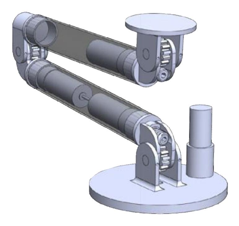
A completely new arm has been designed for the tele-operated robot. This will offer greater mobility of the robot head, which supports the network camera, the IR camera, the CO2 sensor and a simple gripper. The arm, made from carbon fiber tubes, has been designed to support 2kg at a reach of 1m. The arm makes use of Maxon Motors, planetary gear boxes and worm gears to provide the 5 degrees of freedom. A CAD image of the arm design can be seen in figure 2.
Electronics
Access to the electronics, for upgrade and problem solving is key. Previous team's have found removal and insertion a very tricky and time costly process. In order to rectify this the electronics will be assembled in a stack, within a supporting cage. Some circuit boards have been removed and some rotated to allow all electronics to be in the cage. The base of the cage has a number of connectors (provided by HARWIN). When the cage is located on the retaining pins and placed into the robot, the connectors will mate thus connecting all the relevant sensors, motors and other components to the control electronics.
Individual control of each of the motors is key to accurately control the arm. To achieve this control each of the motors in the arm will effectively be turned into high power servomotors. Servomotors consist of four main parts: motor, gears, control circuitry, encoder (potentiometer).
The control circuitry knows what position the motor is in by checking the voltage output from the potentiometer. If the servomotor is not at the correct angle, the control circuitry drives it forwards or backwards to rectify this.
Rapid Prototyped Robot Head
The robot head is attached to the end of the robot arm and houses the infrared camera, webcam, CO2 sensor, microphone, speaker, LED light array, and fan. Its purpose is to protect these components from collisions and dirt in a modular and visually appealing way. The head is to be manufactured using the stereo lithography rapid prototyping method. This method produces a finished part with intricate geometries, which is nearly identical to the CAD model, with the use of a high precision laser of 0.1mm resolution. A part can be produced within hours and the material is light, has a smooth surface finish and is non-permeable.
3 Autonomous
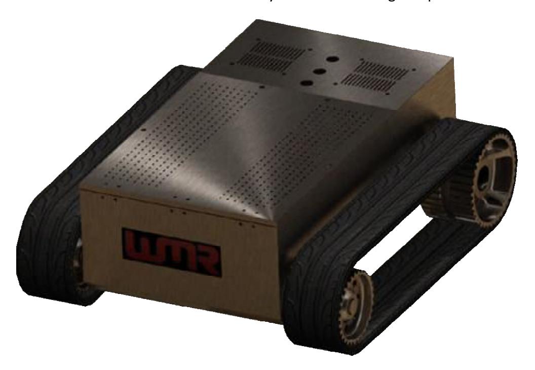
During the initial stages of the project, a decision was made by the team to enter two robots, each specifically designed to meet the requirements of the zones in which they will compete. This meant designing and manufacturing an entirely new robot capable of self-navigation, mapping and indentifying the state and location of victims. In order to reduce the magnitude of the task, the robot was designed to use many of the existing spare components available to the team. In addition, the software design was largely outsourced to a team of Warwick University Computer Science students. A CAD image of the autonomous robot can be seen in figure 3.
Chassis
The autonomous robot is made of 0.9mm sheet steel, which is cut using a laser cutter based on a SolidWorks 2008 CAD model. The steel is formed into the desired shape using a sheet metal hand brake and secured using rivets. The robot design gives the computer science team flexibility to implement various hardware components necessary for autonomous operation, and is sufficient to master the relatively flat terrain during competition.
Electronics
A new internal computer was purchased for the robot to run the software and process the LiDAR data. The main sensor on the robot will be a LiDAR unit, allowing SLAM capabilities and fully autonomous navigation. SLAM (Simultaneous Location and Mapping) is the technique whereby the robot will build a map of its surrounding environment and keep track of its location. Using progressive LiDAR scans of the area in front of the robot as it moves, the software will create and update an internal map. This map can later be retrieved for any subsequent navigation.
The main focus is on keeping the system as similar as possible to that of the tele-operated robot to ensure compatibility and porting of software between the two robots. This will make it possible for future teams to combine the capabilities of the two robots and create one fullyfunctional system.
4 Sensors
An array of different sensors are utilized in both robots for victim identification and mapping. Here is a comprehensive list of the sensors we plan on implementing during the competition:
Victim identification:
Network web-cams provide the visible spectrum images back from the robot. These are used as the primary aid to driving the tele-operated robot.
Infra-red cameras detect areas of heat and display them in the visible spectrum using representative colours for the thermal range.
CO2 sensors are used to measure the CO2 concentration in the air. As the concentration rises the output voltage changes in proportion with the rise, producing varying voltage levels for different concentrations and thus a measurement of the ambient concentration.
Autonomous Mapping:
LiDAR sensors use a laser to progressively scan the environment, measuring the time taken to receive the reflected light back to the device. Building a series of these data points will allow mapping of the environment and aid navigation.
Tilt sensors are able to measure the angle of roll and pitch away from a zero datum at any given time. This is done using a three axis STM accelerometer and an on-board micro processor. As the robot pitches and rolls, the tilt sensor detects it and via software, feeds control pulses to the gimbal.
A gimbal counters those movements, thereby maintaining a level platform at all times regardless of the robot orientation. This stable platform is used to mount the LiDAR.
5 Autonomous mapping SLAM
Simultaneous Localisation and Mapping is the problem of a robot mapping an unknown environment, whilst simultaneously localising itself within the growing map. It combines the well-solved (but coupled) sub-problems of Localisation and Mapping, but there is as yet no complete solution to the SLAM problem. Practically, the issue is optimally interpreting readings from the robot's sensors. Typically solutions include autonomous route planning (SLAMP), but the distinction is rarely made.
Landmark extraction
A common approach is to identify features in the environment to use as a frame of reference. These must be easily re-observable, sufficiently unique and sufficiently abundant. The RoboCup Rescue environment follows a grid pattern, and we therefore implemented a RANSAC algorithm for extraction of wall (and corner) features.
Data association
This is the process of computing a pose estimate by matching a new environmental representation to the current system state. We implemented a Joint Compatibility Branch & Bound algorithm, which is built to ensure that state estimation does not diverge.
State estimation
Crucially, state estimation manages accumulated sensor error, which would otherwise cause the system state to diverge from true real-world state. An optimal estimate of the robot pose and environment must be produced or an approximation thereof, with respect to the confidence in each sensor estimate. We will be implementing a version of the widely used Extended Kalman Filter, based on estimates from odometry and LIDAR.
6 Conclusion
This paper summarizes the approach of the University of Warwick Mobile Robotics team towards the 2010 RoboCup Rescue competition in Magdeburg Germany. Through improvements in our predecessor robot and the implementation of a new prototype autonomous robot, we aim to combine our pervious successes with new innovation in the hopes of expanding our reach in the competition. By weight reduction, a new robot arm and new motors in our tele-operated robot we aim to increase our mobility, longevity and victim identification. Our hopes for the autonomous prototype would be to successfully implement our autonomous mapping and increase our scoring potential in the competition.