RoboCupRescue 2011 - Robot League Team BART LAB Rescue (THAILAND)
Jackrit Suthakorn, Suratana Jantarajit, Woratit Onprasert, Supawat Sarakankosol, Sakol Nakdhamabhorn, Yuttana Itsarachaiyot, Chawaphol Direkwattana, Watcharawit Saensupho, Piyawan Moonjaita, Syed Saqib Hussain Shah
Center for Biomedical and Robotics Technology (BART LAB) Faculty of Engineering, Mahidol University
Abstract 'BART LAB Rescue,' received the 2nd place at the World RoboCup Rescue at Singapore in 2010, and the Winner of Rescue Robot League at the RoboCup Japan Open 2010 at Osaka, Japan, and was the Winner of the 2009 Thailand Rescue Robot Championship (TRR2009), one of the toughest rescue robot league in the world, with a biggest number of participants, 100 high-standard local teams and 6 leading international teams. BART LAB Rescue is, then, the official representative team of Thailand to join the World RoboCup Rescue 2010. The team consists of fifteen members, and three robots. Among the three robots, two robots are tele-operative robots (TeleOpIII and TeleOpIV), and one autonomous robot (AutoBot II). TeleOpIII and IV are highly mobility robots with tracked locomotion system, and are attached with four independently controlled flippers to enhance their mobility. Moreover, inverse-kinematically controlled manipulators, attached with victim-sensing unit at the end-effecter, are equipped on both TeleOpIII and IV. The victim sensing unit includes all possible life-signal detections, such as, heat sensors, real-time motion image detector, Carbon Dioxide sensor, and two-way voice communication system. The third robot, AutoBotII, is an autonomous robot equipped with victim identification system based on image processing and heat imaging technology. The AutoBotII is navigating itself based on laser-scanner system and its efficient algorithm. For all, teleoperative and autonomous robots are equipped with SLAM system to generate reasonable 2-D maps to guide the responders after Rescue Robots raid the disaster area. The ultimate goal of BART LAB Rescue Research and Development team is to produce trustable rescue robots to be employed and ready for real disaster situations around the world.
Introduction
'BART LAB Rescue,' is currently consisting of three robots. Among the three robots, two robots are tele-operative robots (TeleOpIII and TeleOpIV), and one autonomous robot (AutoBot II). BART LAB Rescue has been continuously researching and developing rescue robots, and has been joining the Rescue Robot Competitions in Regional Levels since 2006. In 2008, BART LAB Rescue was one of the 8-finalist among 80 plus teams in the 2008 Thailand Rescue Robot Championship (TRR2008), and was received the Best-In-Class Award for Autonomy. In early of 2009, BART LAB Rescue attended the RoboCup Japan Open 2009 in Rescue League, and received the 2nd Place from the rest 10 Japanese teams. Moreover, BART LAB Rescue was awarded the 'SICE Award' for Data Collection and Management in Autonomous Robot.
In the end of 2009, BART LAB Rescue was awarded the Winner and Best-In-Class Award for Autonomy in the 2009 Thailand Rescue Robot Championship (TRR2009). TRR2009 is one of the toughest Rescue Robot League in the World since there are more than 100 high-standard local teams to join the competition with 6 international teams from 4 countries (CAsualty: Australia, NuTech-R: Japan, NIIT-Blue: Japan, Jacobs University: Germany, Pasargard: Iran, and Resquake: Iran). BART LAB Rescue is, then, the official representative team of Thailand to join the World RoboCup Rescue 2010 which to be held in Singapore.
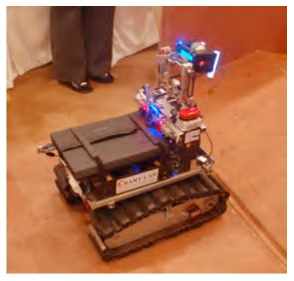
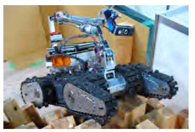
BART LAB Rescue's two tele-operation robots (TeleOpIII and IV) are almost identical in design but they are different in performances with improved driving components in TeleOpIV. Fig. 1. illustrates TeleOpIII. They both are highly mobility robots with tracked locomotion system which makes both robot can mealy be anywhere in orange and red arenas. The robots employ four independently controlled flippers to enhance their mobility (two flippers are in the front end, and the rest two flippers are in the rear end). The tele-operative robots are also equipped with inverse-kinematically controlled manipulators, and attached the victim-sensing unit at the end-effecter to improve their victim's searching and information retrieving. The victim sensing unit includes all possible life-signal detections, such as, heat sensors, real-time motion image detector, Carbon Dioxide sensor, and two-way voice communication system. The manipulator is multi-degree of freedom system with both rotational and prismatic joints for their compact folding size and high efficient workspace. The third robot is an autonomous robot equipped with victim identification system based on image processing and heat imaging technology. The autonomous robot (AutoBotII) is navigating itself based on laser-scanner system and its efficient algorithm, so the robot could navigate along the yellow arena without hitting the wall. Fig. 2. shows AutoBotI, an ancestor of AutoBotII. Both tele-operative and autonomous robots are equipped with SLAM system to generate reasonable 2-D maps to guide the responders after Rescue Robots raid the disaster area.
In conclusion, BART LAB Rescue has a highly mobility set of rescue robots as regularly built by most Thai teams to compete in the previous World RoboCup Rescues. However, BART LAB Rescue has improved a better ability in autonomous robot and a higher quality of real-time generated map from the past. The ultimate goal of BART LAB Rescue Research and Development team is to produce trustable rescue robots to be employed and ready for real disaster situations around the world.
![Fig. 1. The TeleOpIII, one of our two tele-operative robots in BART LAB Rescue team. The TeleOpIII employs tracked locomotion system with 4 independent flippers, and equips with an inverse-kinematically controlled manipulator to enhance more ability to search and retrieve better victim information, similar to other robots in [1,2].](/tdps/rescue_robot__2011__BART_LAB_Rescue/_page_1_Picture_3.jpeg)
1. Team Members and Their Contributions
• Jackrit Suthakorn Team Advisor • Suratana Jantarajit Team Co-advisor • Yuttana Itsarachaiyot Team Manager • Woratit Onprasert Team Leader, and Mechanical designer • Supawat Sarakankosol Controller development • Sakol Nakdhamabhorn Programming (SLAM/MAP) and Communications • Chawaphol Direkwattana Mechanical designer for Camera Manipulator • Watcharawit Saensupho Test field design • Piyawan Moonjaita Inverse kinematic algorithm development • Syed Saqib Hussain Shah Test
2. Operator Station Set-up and Break-Down (5 minutes)
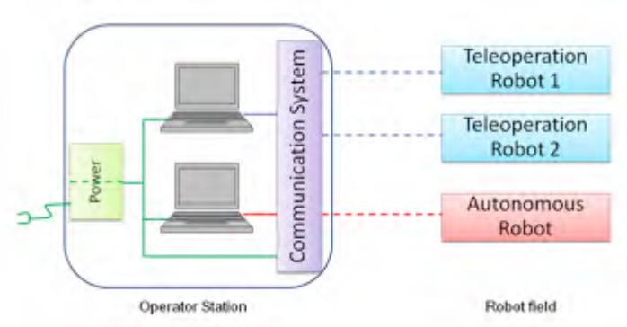
BART LAB Rescue's operator station is a suitcase-size mobile unit. The station system consists of 2 laptop computers, robot controllers (joysticks), backup battery, power connection system, wireless access point system and a large-size monitor system. The system is contained in a wheeled/roughed waterproof suitcase. The operator station is then easy to transport and set-up. The system is to control and communicate to BART LAB Rescue's three robots (TeleOpIII, IV and AutoBotII). A laptop computer is dedicated to two tele-operative robots, and another laptop computer is connected to the autonomous robot. Fig. 3. Illustrates the system of operator station. Therefore, the set-up for the BART LAB Rescue's operator station is almost immediate, and ready to use well maintenance.
3. Communications
BART LAB Rescue employs five access points connecting via Wireless LAN 802.11A to communicate among the three robots. Each robot (TeleOpIII, IV and AutoBotII) is installed with an access point to communicate to two access points at the operator station with bridging technique. Fig. 4. illustrates a diagram to describe BART LAB Rescue's communication system. Channel 60 is used as the default setting; however, the channel can be modified to any requested channel in the available range. There is no RF or Analog wireless communication used by BART LAB Rescue team.
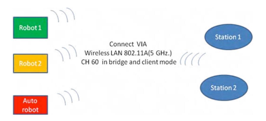
Table 1. Frequency, Channel/Band and Power Table to describe the communcation system of BART LAB Rescue team.
| Rescue Robot League | ||||
|---|---|---|---|---|
| BART LAB Rescue (Thailand) | ||||
| Frequency | Channel/Band | Power (mW) | ||
| 5.0 GHz - 802.11A | 60 | To Be Determined |
4. Control Method and Human-Robot Interface
Control method and human-robot interface of BART LAB Rescue can be separated into two parts; 1) control and interface on tele-operative robot, and 2) control and interface on autonomous robot. Details are described below.
4.1 Control Method and HRI on Tele-Operative Robot
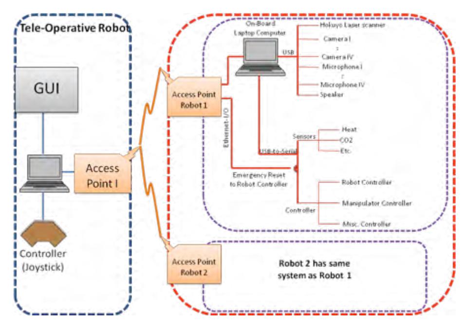
The control system for tele-operative robots is described in Fig. 5. The on-board controlling system communicates to the operator station via Wireless LAN 802.11A access points. On the robot, on-board access point is connected to an on-board laptop computer. Several USB apparatuses, such as, cameras, microphones, speakers and Hokuyo ranging laser-scanner are connected to the laptop. Another USB port is used for USB-to-Serial to communicate with Robot-CPU. The Robot-CPU distributes the controlling command to the platform, manipulator and other controlling subsystems. Under the platform and manipulator subsystems, each individual joint and drive (motor) controller module employs our developed speed/position PID control system. Therefore, feedback control theory is widely used in our robots. An emergency resetting system is prepared to assure and recover the robot controllability when it performs in the remote area, far from the operator station.
The other tele-operative robot has an identical control scheme which allows the flexibility to add more number of robots in the future.
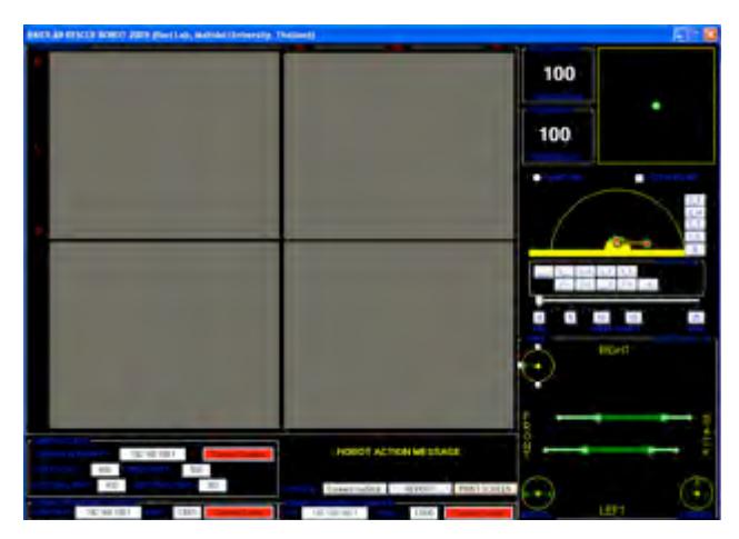
On the operator station, the station's access point is connected to a laptop computer which is connected to a robot's remote controller (joystick), and a display monitor with GUI for HRI. The GUI is illustrated in Fig. 6. The GUI display consists of 4 viewing areas from 4 on-board cameras, sensing data display (heat, CO2, and others), robot heading, communication controller, robot platform's configuration display, pre-set robot configuration controller, and a controller for our inverse-kinematically controlled manipulator.
4.2 Control Method and HRI on Autonomous Robot
The control scheme for Autonomous robot is similar to the tele-operative robot. However, the autonomous robot is required to navigate itself autonomously and also to detect the victim automatically. The map generation, robot navigation and localization will be discussed in section 5 and 6. Also, the victim automatic identification will be discussed in section 7. The autonomous robot is manually launched at the start position, however, the robot is reporting directly to the laptop computer at the operator station which is dedicated to the autonomous robot (see section 5 for the GUI).
5. Map generation/printing
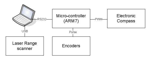
BART LAB Rescue robots have the ability to generate real-time 2-D map which is based on our simple algorithm called "Best-SLAM". The "Best-SLAM" algorithm may be different from others (such as [3]) which is based on matching landmark-to-landmark. Our algorithm focuses on robot's position before start drawing a map. The algorithm is employed a fusion sensing system of ranging laser-scanner (Hokuyo), electronic compass and simple robot's encoders. The laser-scanner keeps sending data which is repeatedly scanned by sweeping 270 degrees on the front of robot. The electronic compass is sending data as the pulse-width-modulation (PWM), and the encoders are also sending data as the pulses to a microcontroller controlling unit. Fig. 7. shows the diagram of how the system is configured to generate the map.
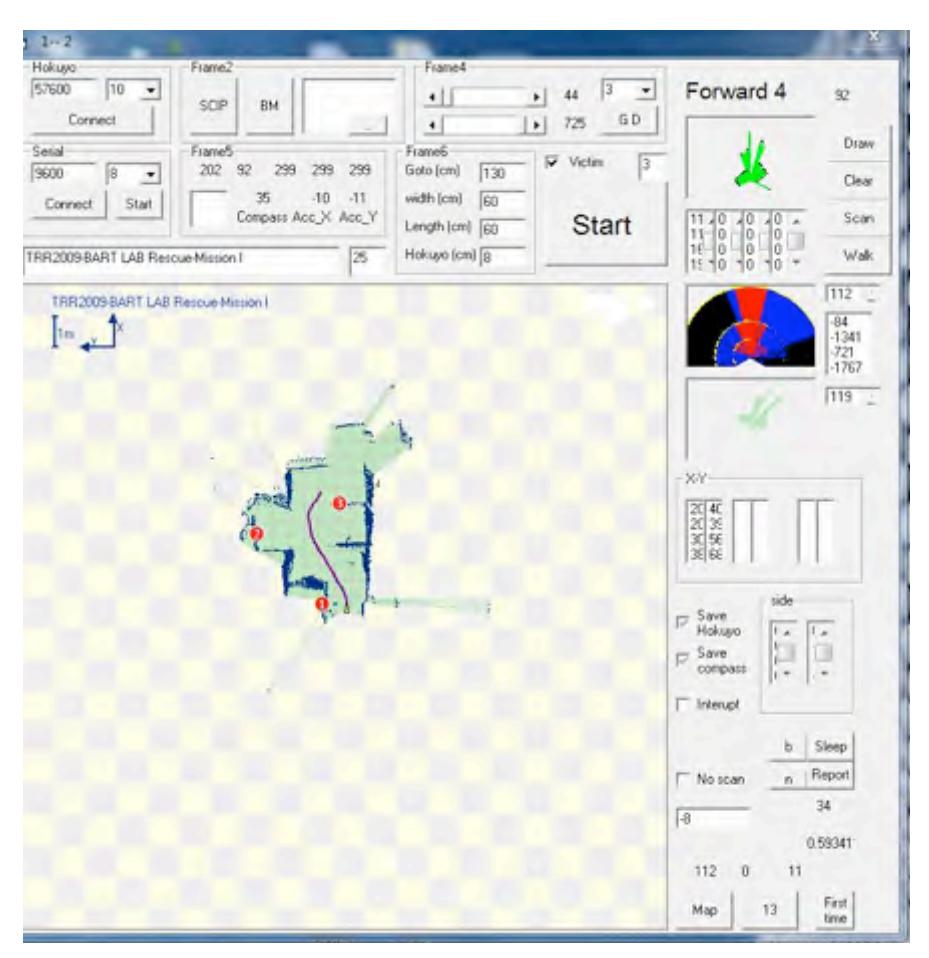
The algorithm starts by collecting laser-scanner data and plotting a map with direction from electronic compass. The robot is assumed to have no-slip motion, therefore, once the robot moves, the data from encoders on left and right tracks are used to calculate the robot's translation. The robot's translation information is also used to shift the generated map by the robot motion. The system is slowly generating the map while the robot's navigation and obstacle avoidance system are based on the generated map. Fig. 8. shows an example of generated map on Autonomous Robot's GUI at operator station.
6. Sensors for Navigation and Localization
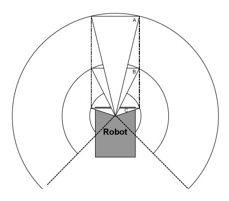
BART LAB Rescue robots are equipped with ranging laser-scanner (Hokuyo), electronic compass, and encoder system. The navigation and localization is based on the generated map described in section 5. The navigation algorithm for autonomous robot is developed, and called "layer-sweeping search." The layer-sweeping search is to split search sweeping into layers by the sweeping diameters. Such as, the robot is searching for the path by checking the opening space. The opening space must have enough width that the robot could go through. Therefore, the search sweeping begins with biggest sweeping diameter.
Condition 1: If the robot could find the opening space with enough width to go through, the robot will mark as its path.
Condition 2: If the robot could not find the opening space with enough width to go through, the robot will reduce the sweeping diameter, and repeat searching for the opening space again.
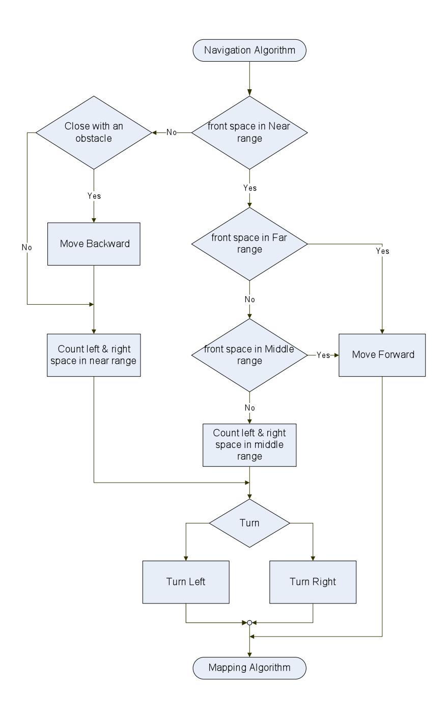
See if the result leads to condition 1 or 2. We found that our simple algorithm is very quick and efficient for the robot navigation in the maze arena. Fig. 9. illustrates the concept of our navigation algorithm, "layer-sweeping search." Fig. 10. shows the flowchart of navigation algorithm.
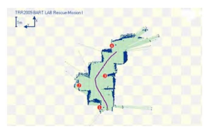
Fig. 11. Shows a closer-look on the generated map, and the results of robot navigation which its path is generated real-time from the "layer-sweeping search" navigation algorithm.
7. Sensors for Victim Identification
BART LAB Rescue robots are equipped with victim sensing unit which contains all necessary sensors to detect the victim life-signals. The sensors are listed below:
- Cameras (for Victim Form and Motion Detection)
- Heat sensors (for Victim Temperature)
- Microphone/Speaker (for 2-way voice communication)
- CO2 sensors
8. Robot Locomotion
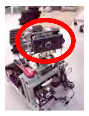
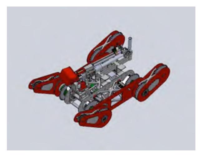
BART LAB Rescue robots have the tracked locomotion systems. The TeleOpIII and IV are similar in the design and locomotion. Moreover, the tele-operative robots are equipped with 4 independently controlled flippers to enhance their mobility. The locomotion is the tank-liked system. Once the left and right tracks are moving in the same direction at the same speed, the robot will move forward or backward. Once the left and right tracks are moving at the different speeds, the robot will make a turn. The maximum speed of the tele-operative robot is almost 0.5 m/sec. The robot can robot about itself at the maximum angular velocity, 1.8 rad/sec. To maintain the stability during moving up/down the ramp and stairway, the robot has to move at a proper speed. Fig. 13 and 14 compare the CAD and Real Image of the robot.
9. Other Mechanisms
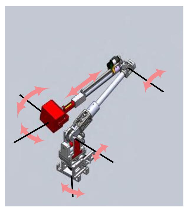
The tele-operative robots are installed with the 6 degree-of-freedom manipulator. The manipulator is designed to used on a highly vibrated with strong shock action during the movement of such rough-terrain robot. The manipulator is relatively light-weight and strong by its structure. The folding size is very compact while the workspace is optimized by using both rotational and prismatic joints. The victim sensing unit is attached at the end-effecter which improve the ability to search and identify the victim conditions. Fig. 15. shows the manipulation's degree of freedom.
10. Team Training for Operation (Human Factors)
A year-round set up of rescue robot arena is arranged for practicing and training at the Mahidol Unversity, Salaya, Thailand. The arena is built and set up follow the NIST suggestions. The arena consists of all zone; red, orange, yellow and blue arena. Therefore, BART LAB Rescue is able to practice and conduct experiments frequently.
11. Possibility for Practical Application to Real Disaster Site
Our ultimate goal is to research and development the trustable rescue robot to be used in the real disaster site around the world. We strongly believe that we are ready to join any rescue task in the real world.
12. System Cost
The following table shows the approximate cost of one robot.
Table 2. Cost Per One Tele-Operation Robot
| Item | Qt | Unit price | Price |
|---|---|---|---|
| y | (USD) | (USD) | |
| Laser-Scanner | 1 | 1,200 | 1,200 |
| Laptop | 2 | 800 | 1,600 |
| Camera | 4 | 100 | 400 |
| Sensor (system) | 1 | - | 500 |
| DC Motors | 6 | 1,000 | 6,000 |
| Electrical Components | - | - | 1,000 |
| Mechanical Parts | - | - | 800 |
| Part Machining/ Misc | - | - | 2,500 |
| Total | 14,000 |
13. Lessons Learned
Team works and Real World Applications.
References
[1] S. Schwertfeger, J. Poppinga, K. Pathak, H. Bülow, N. Vaskevicius, and A. Birk, "Jacobs University," RoboCup Rescue 2009, TDP, Graz, Austria, June 2009. [2] T. Nakaya, "NuTech-R," RoboCup Rescue 2009, TDP, Graz, Austria, June 2009 [3] R. Sheh, A. Milstein, C. Sammut, B. Hengst, G. Dissanayake, and J.V. Miro, "Team Casualty," RoboCup Rescue 2009, TDP, Graz, Austria, June 2009.