RoboCupRescue 2011 - Robot League Team Chitose (Japan)
Hikaru Sugiura, Masato Muraki, Shunki Takami, Ryo Tomita, Yusuke Kitagawa
Aichi Institute of Technology; Meiden High School Information Design Club
http://teamchitose.blog3.fc2.com/ · http://www.youtube.com/watch?v=f6lUixdMc54
Abstract Our team is organized only high-school students. This paper describes how to make robot that can participate to Robocup Rescue Robot League by high-school students. Our robot is so low cost. we think team from Robocup junior can refer this approach and they can challenge Robocup Rescue Robot League as next step of Robocup Junior.
Team Information
3-2-12 Wakamizu, Chikusa-ku, Nagoya 464-8540 Japan

Introduction
Until season 2010, we participated to robocup Junior league. Junior League ' s main purpose is Developing next generation robotics researcher.
Recently, I think many Robocup junior teams have high-technology that can participate to major league.
We want to show to junior team that the team from Robocup Junior can participate to the "major" league as next step of junior league.
To achieve this purpose, Our concepts are Cheep System, Developed by only under 18 years old people.
1. Team Members and Their Contributions
• Hikaru Sugiura Circuit and embedded program • Shunki Takami Network program and GUI
• Yusuke Kitagawa 3D GUI program
• Masato Muraki Mechanical design and manufacture(Gearbox) • Ryo Tomita Mechanical design and manufacture(Camera arm)
• Tomoaki Nakayama Club teacher
• Akihito Sugiura Adviser
2. Operator Station Set-up and Break-Down (10 minutes)
The operator's operation
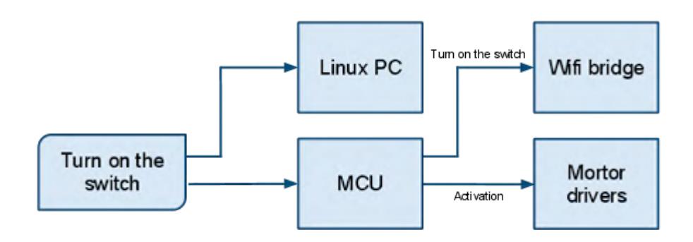
Turn on the switch of the robot. Starting the operating application. The robot startup at about 50 seconds.(Notify system started sign to operator PC) Startup completion!!
Internal behavior
Startup sequence as shown in figure.
3. Communications
The communication between operation PC and the robot uses only WiFi. We mainly use only 802.11a/48ch(5GHz), but if the trouble occurs, we plan to use other channel of 802.11a(36ch,40ch,44ch,52ch,56ch,60ch,64ch) and 802.11g.
| Rescue Robot League | |||
|---|---|---|---|
| Chitose (Japan) | |||
| MODIFY TABLE TO NOTE ALL FREQENCIES THAT APPLY TO YOUR TEAM | |||
| Frequency | Channel/Band | Power (mW) | |
| 5.0 GHz - 802.11a | 48ch (36ch,40ch,44ch,52 |
8.5 | |
| 2.4 GHz - 802.11b/g | ch,56ch,60ch,64ch) 1-12ch |
8.5 |
4. Control Method and Human-Robot Interface
Construction of Robot Control System
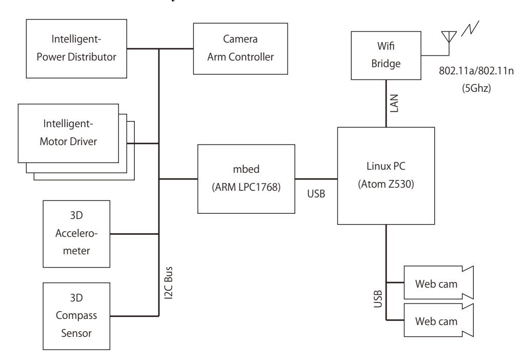
The robot's block diagram is shown in (fig4.1.0).
The robot has 3 kind of processor, Intel Atom(x86), ARM(mbed) and Renesas M16C(Motor Driver).
4.1.1 Linux PC
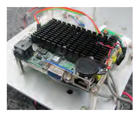
Because of out robot is small, embedded PC have to be small(power and size).
This is a PC, called Pico820(Fig 4.1.1),form factor of PICO-ITX(100mm×72mm).
It uses Atom Z530 Processor and can drive only 5V 1A(5W). Low power processor also contribute to battery life.
The PC is installed Ubuntu 10.04.
And, it is used for a LAN-Serial command bridge and a camera and mic server.
4.1.2 mbed (Intelligent USB Serial-I2C Bridge)
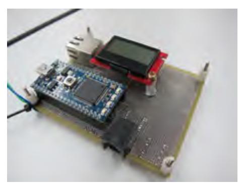
We use mbed 1 controller to Serial-I2C bridge.
When Linux PC send command to mbed controller, mbed assess to each I2C device depending received command. Command example is shown below.
[FlipperFrontLeft move back,2500]
This command means "Move flipper of front left to 250.0 degree, spin back direction".
We plan to connect to ethernet directly ,not via PC.
4.1.3 Intelligent-Motor Driver
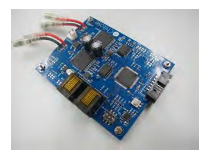
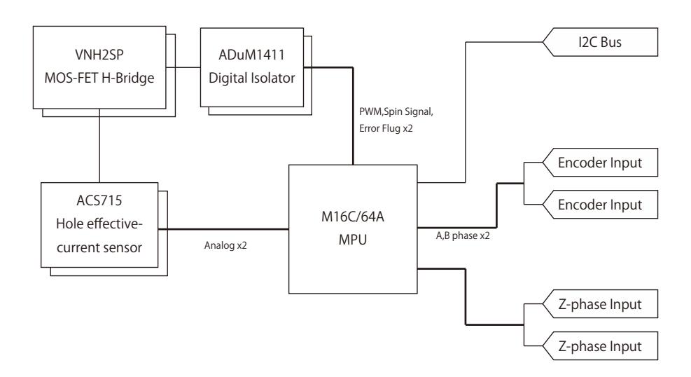
We developed "Intelligent-Motor driver" to control flippers and crawler.
Features
- M16C/64A(Renesas Technology) Micro controller used
- I2C Bus
- VNH2SP(ST Instruments) Motor Driver, that can drive up to 30A.
- Watch each motor's current
- Manage flipper position(Encoder)
1 mbed.org
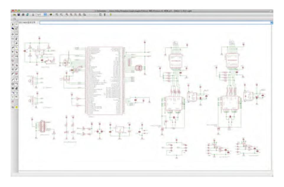
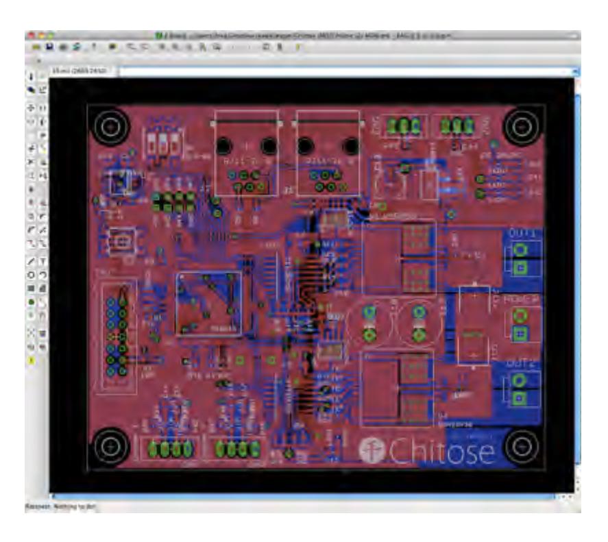
For designing circuit and PCB, we use Eagle Cad. It is free to use and it can design up to 100mm × 80mm.
We ordered manufacturing PCB to "Fusion PCB". by this, we can hold down PCB cost. US$7.00 per board.
4.2 Human-Robot Interface
The human interface provides intuitive operation. For example, show controller on camera window, the 3D model operation, and the operation by the one click, ...etc. In a word, most training is not needed. And it reduces the human-error.
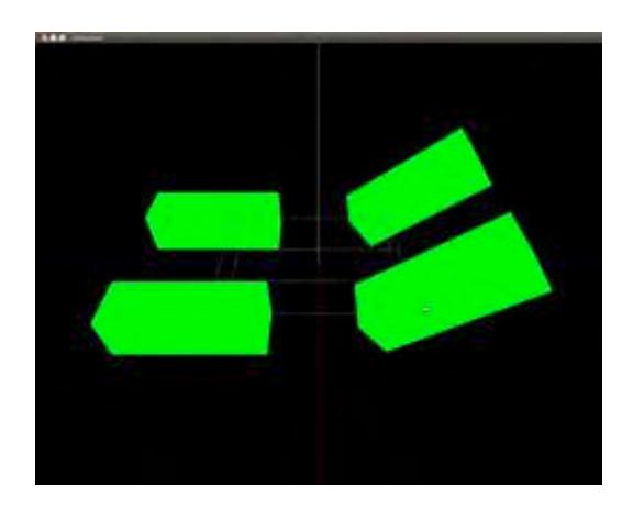
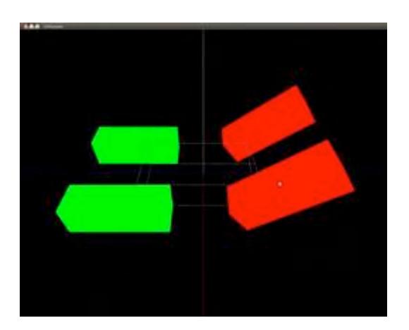
4.2.1 Virtual 3D model
It takes a certain period to get used to operating at a first time if operate it with joystick.
So, we developed the way to operate a robot by transfer data through operating 3D model on a screen with mouse. We used openGL for the operation by 3D model.
In this way anybody can operate a robot in an intuitive and the easy way.
4.2.2 Camera Viewer
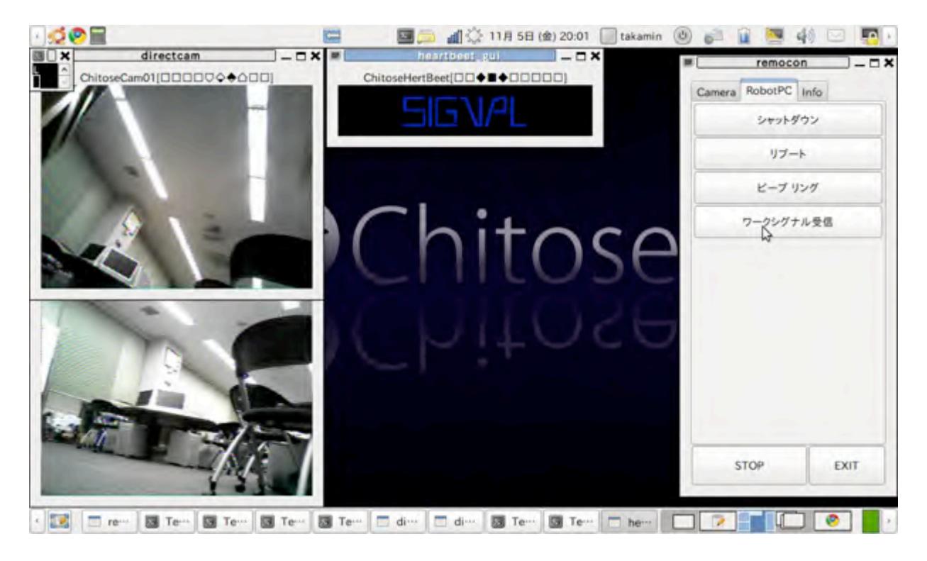
The camera viewer developed with GTK+. The image data is compressed by thinning out the image. It can compress the volume of data of 1/3. So we are possible to watch by a high frame rate video. In addition, the compression method can be switch according to the situation in the future.
5. Map generation/printing
Handwriting by seeing camera image.
6. Sensors for Navigation and Localization
Operators can't understand robot's situation because they can not see robot directly.
To see situation of robot, show details of 3D accelerometer and compass sensor to 3D model.
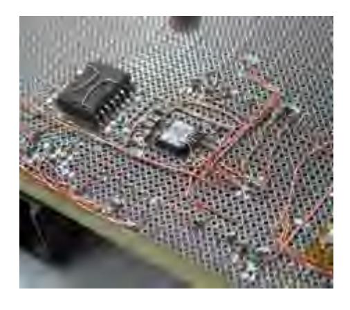
3D Accelerometer is mounted in mbed controller board.(fig 6.1.0) This sensor is connected with I2C bus.
"mbed" return acceleration(gravitation) when receive command below.
[Accel Get]
Prototype movie is uploaded to Youtube (http://www.youtube.com/watch?v=f6lUixdMc54).
7. Sensors for Victim Identification
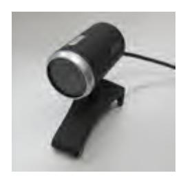
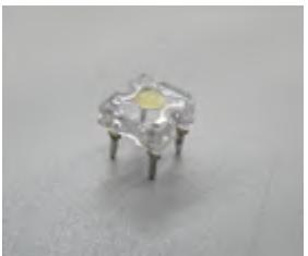
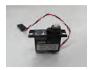
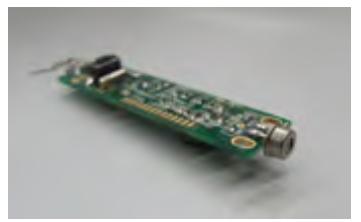
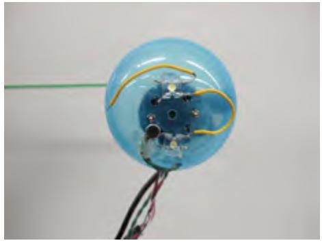
Because we use the convex measure as arm, sensor to find the victim attached to tip of arm should be light.(Reference to chapter 9) So we make sensor module uses small sensors and camera taken apart. Sensor module has various device below.
- Camera (Fig 7.1)
- Microphone (Fig 7.2)
- LED light (Fig 7.3)
- RC servo motor (Fig 7.4)
- (Temperature sensor) (Fig 7.5)
Moreover, the capsule which was embed to sensor is also move to pitch and yaw axis, and the LED is embedded to tip of capsule to find the victim. From these, there is not dropping performance, we could success to light the sensor.

8. Robot Locomotion
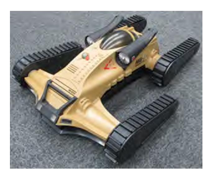
The robot is based on tarantula which product of MGA Entertainment (USA).
Why we used it has a 4 flippers and it is very cheap.
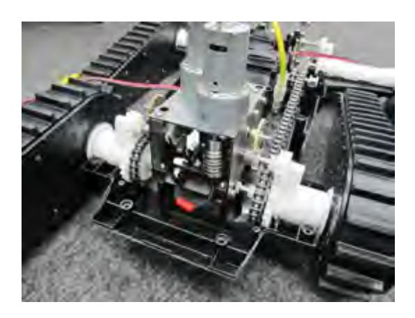
Right flipper and left flipper is synchronized.(Fig 8.1)
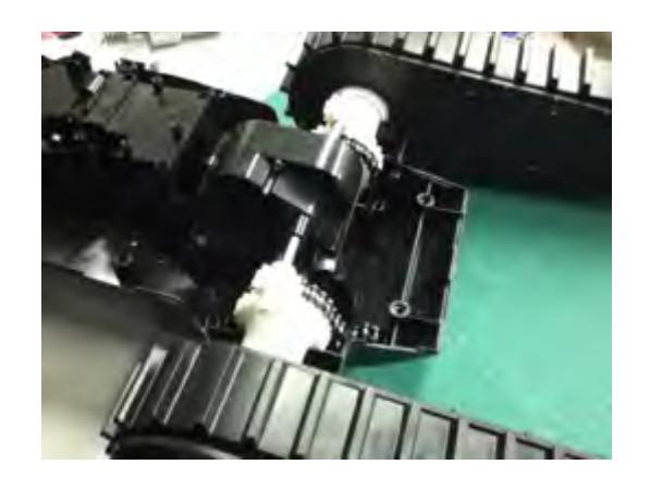
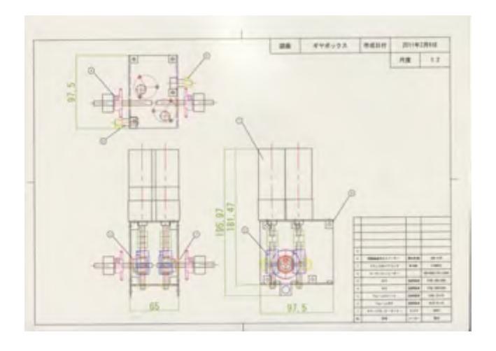
So we designed to moves separate.(Fig 8.2) Gear box is designed easy to manufacture. New gear box cost is about 25,000 JPY per one gearbox.
Gear Box BOM(All price in JPY)
| QTY | Desc. | Part No | Vendor | Unit Price | Cost |
|---|---|---|---|---|---|
| 2 | Worm gear | W1SU R1+B | KG gears | ¥2,300 | ¥4,600 |
| 2 | Worm gear wheel | G1DB 20+R1 | KG gears | ¥1,100 | ¥2,200 |
| 2 | Gear Motor(380 motor) | 89861 | TAMIYA | ¥4,500 | ¥9,000 |
| 2 | Gear | S75B 20B + 0306 | KG gears | ¥450 | ¥900 |
| 2 | Gear | S75B 50B + 0306 | KG gears | ¥450 | ¥900 |
| 2 | Coupling | CPL-14-RD-6-6 | MISUMI | ¥1,300 | ¥2,600 |
| 2 | Shaft | SFHKR6-70 | MISUMI | ¥400 | ¥800 |
| 4 | Ball bearing | FL686ZZ | MISUMI | ¥440 | ¥1,760 |
| 8 | Board Mounter | VAB-10E | Hirosugi Keiki | ¥70 | ¥560 |
| 2 | Encoder | EM14-64 | Bourns | ¥1,600 | ¥3,200 |
| Total Price | ¥26,520 |
(Total price about 320USD)
9. Other Mechanisms
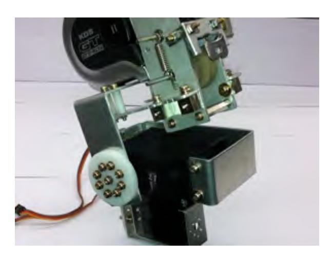
Because of our robot is small, the camera arm mechanism have to be small. Then, we designed small arm mechanism which have pitch and yaw axis. In designing stage, we thought that the extending mechanism also have to be small.
So we guess the convex mesure is suitable to extending mechanism. We tried to compare various companies convex mesure. In result, the convex mesure, product of KDS has the highest rigidity than other one, so we decided to use it.
Thanks to this, we success to small the extending mechanism. In next, we thought how the pitch and yaw axis mechanism to miniaturize. For that, we have to use the servo motor which is small and high torque. So we chose the cheep RC servo motor in TowerPro company. As a result, we can small to the mechanism which have pitch and yaw axis. From these, we can success to make the arm mechanism of suitable for robot.
10. Team Training for Operation (Human Factors)
By user friendly interface, no training is needed to operate the robot.
11. Possibility for Practical Application to Real Disaster Site
How much cheaper is important to use Rescue robot in real disaster site. It is able to make robot at low cost by using consumer products. Our knowhow may contribute to develop cheaper robot.
12. System Cost
BOM(price in JPY)
System Cost BOM
| QTY | Desc | Vendor | Part No. | Unit Price | Cost |
|---|---|---|---|---|---|
| 1 | Embedded PC | Axiomtek | Pico-820 | ¥36,000 | ¥36,000 |
| 1 | Base of Robot | MGA Entertainment | Tarantula | ¥5000(US$60) | ¥5,000 |
| 3 | Intelligent Motor Driver | Original | - | ¥10,000 | ¥30,000 |
| 2 | Original Gearbox | Original | - | ¥26,520 | ¥53,040 |
| 1 | Camera Arm | Original | - | ¥8,000 | ¥8,000 |
| 1 | Arm Controller | Original | - | ¥2,000 | ¥2,000 |
| 3 | USB Camera | Buffalo Japan | BSW13K05HBK | ¥1,950 | ¥5,850 |
| 2 | Li-Po Battery | Hyperion | - | ¥7,000 | ¥14,000 |
| 1 | Wifi Bridge | Buffalo Japan | WLAE-AG300N | ¥5,463 | ¥5,463 |
| 1 | mbed microcontroller | NXP | mbed LPC1768 | ¥5,600 | ¥5,600 |
| Total cost | ¥164,953 |
(Total price about 2,000USD)
References
[1] mbed.org