RoboCupRescue 2011 - Robot League Team Lumunite (Pakistan)
Aneeq Zia, Adnan Munawar, Usama Sikandar, Muneeb Zia, Umair Shafique, Nauman Butt
LUMS School of Science and Engineering D.H.A, Lahore Cantt, 54792
Abstract This Team Description Paper highlights the features of 'Lumunite' search and rescue robot. Lumunite is a tracked robot with all the essential sensors for victim identification and simultaneously mapping of its surroundings. It is designed to be fast and flexible. High torque differentially steared with cleated rubber tracks, light weight body and low center of gravity ensures maneuverability over rough and difficult terrains such as inclined surfaces, stones, gravels and other wreckage.
Introduction
Lumunite was initiated with a vision to ultimately aid and reinforce the emergency response agencies of Pakistan in the occurrence of a disaster. The team consists of mainly undergraduate students who have participated in various national robotics competitions like National Engineering and Robotics Competition, Robowars, Nascon etc. With this diversified experience, the team has now undertaken this initiative. Lumunite is a tele-operated robot with all the essential sensors for victim identification. It is a tracked robot with high mobility capable of maneuvering in difficult terrain and map its surrounding simultaneously.
1. Team Members and Their Contributions
Aneeq Zia Team Leader and Control Design
Muneeb Zia Sensor Interfacing Umair Shafique Mechanical Deisgn Adnan Munawar Mechanical Design
Usama Sikandar Electronics
Nauman Butt Communication and SLAM
Dr. Abubakr Advisor
2. Operator Station Set-up and Break-Down (10 minutes)
The operator alone will setup while 2 other members of the team place the robot in the arena. Notebook, controller and printer are packed in a case which can be quickly opened and connection established with the robot in less than 10 minutes. At the end of the mission, the operator can quickly print the map generated during the run.
3. Communications
Team Luminite is using Linksys by cisco WRT610N Simultaneous Dual-N Band Wireless Router which supports 802.11a, 802.11g, 802.11b, 802.3, 802.3u, 802.3ab standards. We are using only 5GHz radio band with IEEE 802.11a standards for primary communications purposes.
Robot locomotion control, video stream from cameras, sensor data feedback for obstacle avoidance, current robot status and victim identification are being sent over this wireless network.
Communications Specifications - Luminite (Pakistan)
| Frequency | Channel/Band | Power (mW) |
|---|---|---|
| 5.0 GHz - 802.11a | Selectable | 25mW |
4. Control Method and Human-Robot Interface
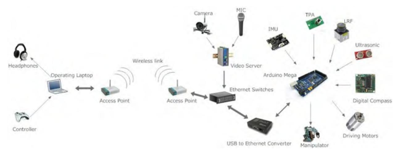
Lumunite is a tele-operated robot with provision for partial autonomy to override the operator if the robot is about to bump into the arena; the robot has the capability to avoid obstacles autonomously in case of radio link drop out.
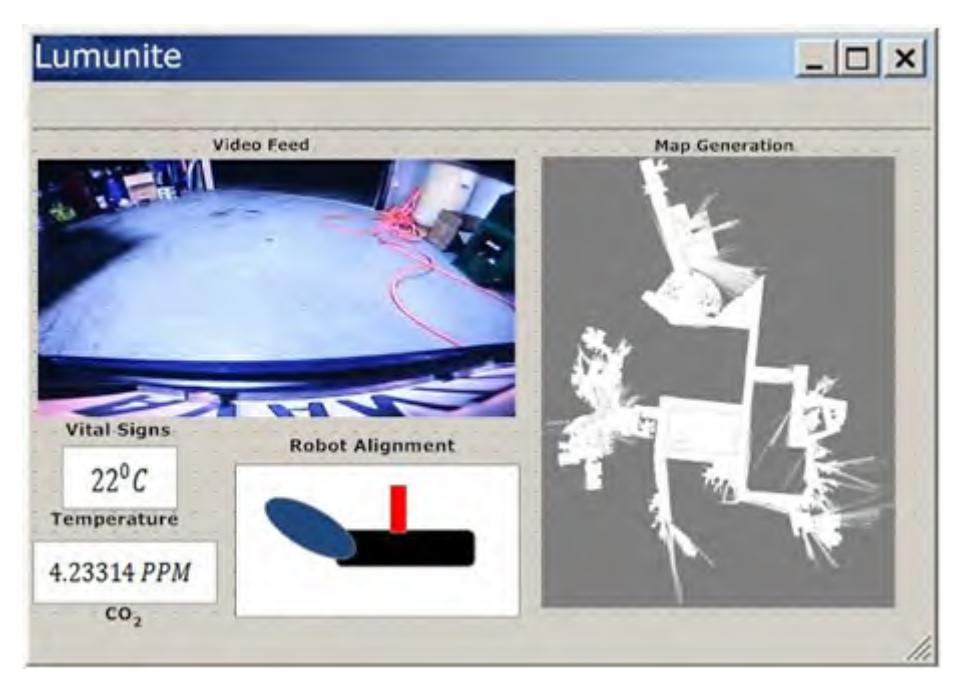
XBOX controller is being used by the operator to control the robot. The GUI displays for the operator, camera feeds from three cameras, robot orientation, temperature of the manipulator surroundings and CO₂ concentration.
The Robot Control is based on Arduino Mega with AtMega 2560. The main work of the controller can be categorized as following:
- Motor Driving
- Sensor data processing
High Rating DC motors are used to drive the belt on the flippers along with servo motors to control the position of the flippers. The servo motors used in the manipulator are controlled through the same microcontroller board.
Output data from various sensors mentioned in the Sensors section will be given as input to the controller. The micro-controller, after processing it, sends the data out through a USB port. As the Access point needs an Ethernet input hence the data send via USB port is fed into a USB to Ethernet convertor and then fed into the Access point for WLAN communication.
5. Map generation/printing
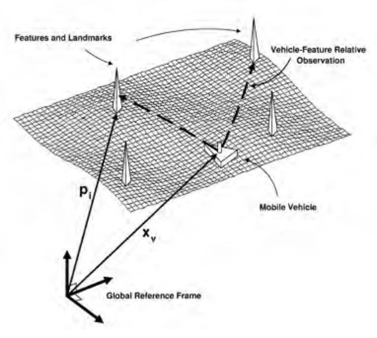
We will be using SLAM algorithm for localizing the robot and for building an incremental navigation map with the observed features. The robot will be equipped with sensors capable of taking measurements of the relative location of the feature and the robot itself. This scenario is shown in the figure below:
The map is generated by incorporating the information taken from different sensors into the SLAM algorithm. The sensors which we are using are encoders for measuring the distance the robot moved, Inertial Measurement Unit for knowing the inclination of the robot and for getting the direction in which our robot is heading, IR displacement sensors and laser range finder for sensing the distance between robot and obstacles.
6. Sensors for Navigation and Localization
Lumunite has three wide angle cameras to assist the operator in navigating through an unknown terrain as seen in. The operator can see 2 video feeds; the feed from the camera mounted on the manipulator is permanent while the other feed can be switched between the front and the rear camera. Moreover, Lumunite uses other sensors for navigation and localization. These include:
Laser Range Finder
Laser Range Finder is being used to detect obstacles around the robot and use this data in conjunction with that of the robot heading and distance moved from the other sensors to generate the map.
Optical Shaft Encoder
Optical shaft encoders are being used to calculate the distance moved by the robot.
Inertial Measurement Unit
IMU is being used to determine the tilt angle of the robot and the heading of the robot; both these measurements are aiding the map generation and are also assisting the operator by displaying the orientation of the robot.
Infra Red Ranger
IR Rangers are being used to calculate the distance of nearby obstacles from the robot and the data used to reinforce the data from LRF.
Ultrasonic Sensor
Ultrasonic sensors are being used to detect obstacles and prevent arena bumping.
7. Sensors for Victim Identification
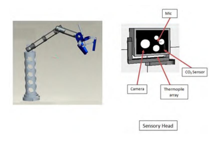
All sensors for victim identification are placed in the housing on the manipulator. Sensors used for victim identification are:
Thermopile Array
8 pixel Thermal Array sensor is being used to measure the temperature of the victim and is being displayed on the interface.
CO₂ Sensor
CO₂ sensor is being used to determine the level of CO₂ in the vicinity of the victim. The concentration is being displayed on the operator interface.
Microphone
A high quality microphone coupled with a speaker is being used to communicate with the victim.
Camera
Camera mounted on the manipulator sends video feed to the operator for victim identification. Motion detection algorithm is also implemented on the operator end. The camera used performs sufficiently well under very poorly lit environments.
8. Robot Locomotion
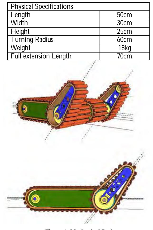
The locomotion of mobile robots in the undeveloped outskirt area is one of the most difficult demands for the system. On one hand, as an outdoor robot, it has to be fast and flexible; on the other hand the vehicle has to deal with difficult grounds such as stones, gravel or stairs. Other important requirements include the system to be robust as well as lightweight to make it more efficient. In order to maximize the performance and achieve all terrain capabilities, Lumunite is differentially steered with cleated rubber tracks; this type of drive system is equally good for flat grounds and rough terrains (including randomly elevated block floor, stairs etc.). Each drive system consists of two of 24V, 95 rpm DC motor for the movement on the left and right. Lumunite's body and structure of drive system is made up of aluminum. The belt is made of synthetic rubber. Low center of gravity and ample ground clearance were kept under consideration while designing Lumunite. The robot has a pair of flippers (front). Each flipper can be rotated 360 degree and they work independently of each other. Therefore, the robots have good terrain adaptability for moving through disaster area.
MANIPULATOR
A very important feature is the robotic arm mounted at the top of the vehicle. The sensory head includes a video camera, thermopile array, microphone and CO₂ sensor installed on the last link of the manipulator. It can be rotated 360 degree and can be extended closer to the victim, if necessary, to increase visualization. The joints of manipulator are controlled by reliable motor drivers and servo motors using accurate shaft encoders. The end effector can also be used to pick objects, this is designed to bear payload around 2kg.
9. Possibility for Practical Application to Real Disaster Site
As discussed earlier Lumunite was conceptualized to aid Pakistan's emergency response system. Its mechanical design is such that it can maneuver over wreckage in any real disaster situation.
10. System Cost
The costs of the parts used for the construction of Lumunite are as follow:
System Cost Breakdown
| Component | Quantity | Cost |
|---|---|---|
| Mechanical Construction | $1000 | |
| Sensors | ||
| Digital Compass | $100 | |
| Thermopile Array | $80 | |
| Sonar Sensors | 4 | $150 |
| Infra-Red Range finder | 3 | $50 |
| Laser Range finder | $1000 | |
| Microphone | $50 | |
| Video Camera | 3 | $200 |
| 3-axis Accelerometer | $100 | |
| Arduino Mega | $80 | |
| DC Motor | 5 | $900 |
| Servo Motor | 2 | $100 |
| Communication System | ||
| Access point IEEE 802.11a | $80 | |
| Video Server | $150 | |
| Converters | $200 | |
| Total Cost | $3970 |
References
- Eduardo Nebot: Simultaneous Localisation and Mapping (2002)
- Ozkan MS., Aydin CM. and Ozdemir A. Position Detection Using Ultrasonic Sensors, 2004
- Köhler M., Patel SN., Summet JW., Stuntebeck EP. and Abowd GD. TrackSense: Infrastructure Free Precise Indoor Positioning Using Projected Patterns, Institute for Pervasive Computing, Department of Computer Science ETH Zurich, 8092 Zurich, Switzerland