RoboCupRescue 2011 - Robot League Team Serendipity (Pakistan)
Mirza Sheharyar Baig
National University of Sciences and Technology H-12, Islamabad, Pakistan
Abstract This paper makes a fair attempt of presenting a synopsis of the aspects covering mechanical design and fabrication, control method and concept behind the tracked robot for Rescue Robot League 2011 in RoboCup 2011. The main objective of this project is to develop a robot that can pave the way for future research in the field of mobile rescue robots ultimately leading to a fullfledged product capable of being marketed and commercialized.
Introduction
We are a group of students from National University of Sciences and Technology aiming to develop a tracked rescue robot that can be used to navigate in the rubble of buildings collapsed due to earthquake or bomb blast and find victims trapped underneath. Our objective is to come up with a practical prototype that can be used in actual rescue missions. It would serve as a foundation stone for future development in the field of mobile rescue robots. Although the project is being sponsored by National University of Sciences and Technology, we are always in search of new sponsors as funds are not enough.
Our primary goal is to participate in the Rescue Robot League using it as a springboard to develop a full-fledged product. Some of the project targets have been met. Software programming, basic drive control (embedded programming) and chassis design have been completed. Work on Localization and Mapping is underway and will be completed before the May this year.
The after math of the October 7th 2007 earthquakes in Pakistan and the devastation aggravated by the distinct lack of equipment and technical skills of the rescue services motivated us to take this initiative. Also, this project best suited us for being students of Mechatronics Engineering. It presented us with an opportunity to utilize whatever we have learned in the past 3 years of our degree program to come up with a rescue robot that would at least serve to highlight the importance and advantage of mobile robotics in search and rescue operations.
1. Team Members and Their Contributions
List of team members along with technical contributions.
• Ahmed Hassan Khan Embedded Programming • Zohaib Ahmed Siddiqui Embedded Programming • Ziad Javed C# Graphic User GUI • Mirza Sheharyar Baig CAD Mechanical design/ Fabrication • Ahmed Asad Control Box/Design/Fabrication • Osama Siraj CAD Mechanical design/Fabrication • Usman Ahmed Jan Electronics/ Wiring
• Haider Bashir Operator • Dr. Javed Iqbal Supervisor • Ghayur Ahmed Shah Mentor • Muhammad Hassan Fidai Mentor
2. Operator Station Set-up and Break-Down (10 minutes)
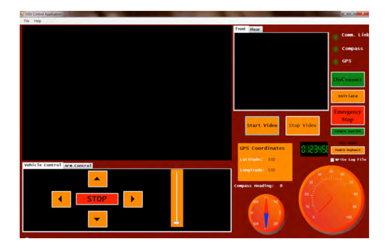
The Operator Control Unit (OCU) consists of a Laptop encased in a Polypropylene portable case similar to a plastic toolbox. The case has been designed keeping in mind adequate cooling and ventilation during operation. The Operator will use the Playstation® 2 gamepad for controlling the robot or LogicTech Attack 3 joystick. The video from the camera will be streaming in from the analogue camera mounted on the robot; live video will be displayed in the GUI. The GUI developed in C# using .Net libraries will have speed, compass bearing and GPS being displayed to the operator in the form of GUI Widgets. Also, buttons have been provided in the GUI for controlling the robot through mouse and keyboard. The camera has been mounted on a pan-tilt platform, controlled by one of the PlayStation2 Pots. The Video Transmitter and RS232 Data transmitters will be housed inside the case.
3. Communications
Audio/Video transmitter and receiver pair is used to relay visual and auditory information to the human operator. The analogue pan-tilt camera mounted on the tracked robot is connected to a transmitter with a range of approximately 1km. Video transmission and reception has been tested and effective transmission range is near 1km. Testing was done with receiver inside a closed room in a 2 storey building and transmitter being held by a team member moving away from the building at walking pace, using walkie-talkie to communicate with another member monitoring video inside the room. Glitches in transmission were noted above 1km range.
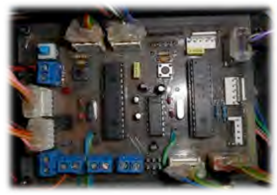
Commands and information encoded in data packets is sent and received through RS-232 transceivers also having an effective range of 800-700m. The transceivers on board the robot is connected to a dsPIC 30F2010 which receives the data packet and decode actions need to be performed. Fig.2 and Fig. 3 show the data packet and PIC circuitry respectively.
Data Packet Protocols
| C A Protocol | B Protocol | |
|---|---|---|
| Header | = S (0x24) | Header = $ (0x24) |
| Byte2 Byte3 | Compass Bearing High Byte = Compass Bearing Low Byte = left motor encoder tions, resets after 100 revs | Byte1 |
| = left motor Speed | Byte2 | |
| Byte3 | ||
| 100 1100 | - Battery indication; = Reserved | Byte4 Byte5 |
| ė. Byte7 Byte8 | - Reserved | Byte6 Byte7 |
| Footer | = 0 (0x55) | Byte8 Footer |
Frequency Allocations
| Rescue Robot League Serendipity (Pakistan) | ||
|---|---|---|
| Frequency | Channel/Band | Power (mW) |
| 2.4 GHz - 802.11b/g | - | |
| 2.4 GHz others | 4 Channels (2.413-2.430Ghz) | 3000 |
| 900 MHz | ISM 900MHZ | 1000 |
| 5.5Mhz | Audio Carrier | - |
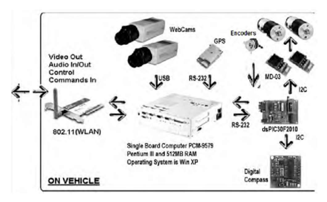
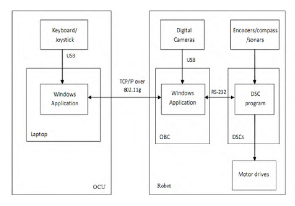
At present we have also developed an alternate system altogether illustrated by Fig.4. In this setup an on board Pentium III SBC (single board computer) with a WLAN card 802.11a/802.11g will be used to communicate with the OCU. The SBC is linked to the dsPIC 30F2010 controllers via serial port (RS232). Also a USB webcam camera is interfaced with on board SBC using a tuner card. However, video transmission lag due to compression time during processing compromises the feasibility of this setup. Nonetheless we have option to utilize one any of the communication schemes mentioned above to implement effective fool proof communication.
4. Control Method and Human-Robot Interface
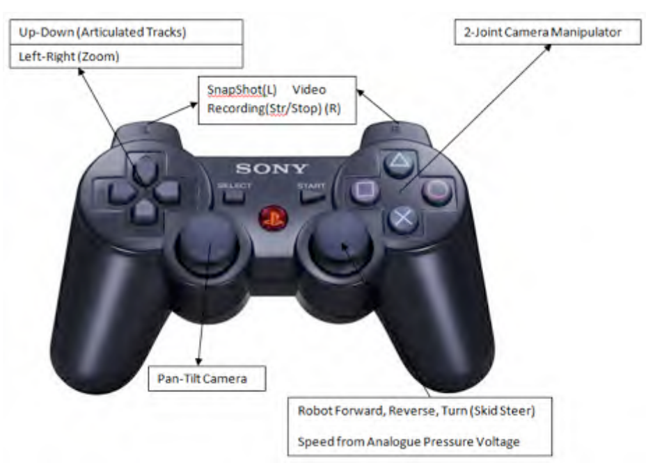
The robot is remote tele-operated by a human operator. The operator will perform all necessary actions, including moving the articulated tracks to climb stairs and overcome obstacles. Maneuvering the pan-tilt and 2 joint camera manipulator, monitoring the battery status as displayed in the GUI, listening for auditory signals from victims will be some of the actions performed by the operator. Also as more sensors and features are incorporated operator will be expected to perform actions and make necessary decisions. Actions such as taking snap shots of victims, video recording and playback, zoom, pan-tilt have been programmed to be done through Gamepad buttons to avoid overwhelming the operator. One of the two POTs on the PS2 game pad will be used for forward, reverse and turning actions of the tracked chassis.
5. Map generation/printing
Sonar range finder interfaced using I2C will be used to draw a map of the simulated arena. The objective would be to generate a map and make allowance in the GUI for the user to mark victim locations on the generated map.
6. Sensors for Navigation and Localization
An array of 7 Ultrasonic sonar transmitter and receiver pair will be used for mapping and localization however, this part of the project is under development and while be completed in due course. Our plan is to increase the number of analogue cameras to 2 ( one at the front end inside the chassis to provide ground level view and one rear). A video multiplexer controlled by the microcontroller would be used to switch between camera feeds.
IMU (inertial Measurement Unit) may be used to control acceleration and speed while navigating. Also encoders have been used for PID algorithm implementation for accurate speed and position control while turning. PID algorithm is used to determine the duty cycle of the Pulse Width Modulated Waveform signal to the drive controller.
7. Sensors for Victim Identification
Work is underway; sensor selection, quotation enquiry and circuitry design is being carried out. The circuits will be ready to test along with the algorithms within one month.
8. Robot Locomotion
The robot consists of a tracked chassis platform. Two articulated tracks/ arms are attached to the front drive pulleys/rollers to negotiate obstacles and climb stairs. The front and rear drive High Density P.E drive pulleys are linked by a rubber track. Each drive pulley is driven by a 36V, 80W (x4) DC brushed motors, with gearbox (right angle). The Articulated tracks are driven by a common shaft driven by a 36V, 100W worm geared motor. All motors are equipped with shaft encoders.
9. Other Mechanism
Articulated tracks/flippers each attached to front drive sprockets help the robot to climb stairs and overcome variety of obstacles. However, 2 DOF, simple robotic arm has been used to move the main pan-tilt zoom camera over obstacles or to look into hard to reach areas.
10. Team Training for Operation (Human Factors)
The learning span of the GUI and interface is 15min. The OCU( operator control unit) is very easy to operate. The operator has to start the GUI application, which initializes RS-232 module for Data transmission by itself. As mentioned earlier two setups have been developed for communication; both using the same GUI. When Single Board Computer is used, video is displayed in the GUI.
In the second scheme when RF Video transceiver is used video is relayed to a TFT screen directly connected to the receiver.
The operator only needs to be familiar with PS2 gamepad interface, it takes few minutes to memorize key functions. However, climbing stairs can some times pose a challenge. Our operator has been practicing by climbing stairs, navigating around football field, climbing over curbstones and rough terrain in and around the campus. And practicing moving the robot over broken concrete slabs and wooden blocks.
11. Possibility for Practical Application to Real Disaster Site
Although our robot is still under development and has not yet harnessed the capabilities compared to those available in the market. However, the robot has shown tremendous versatility. It can be maneuvered on concrete rubble although we have tested on broken concrete slabs, however, it is yet to meet the basic standards and capabilities of a commercially available robot. One of the challenging factors is the running time of the batteries. Designing a 5 DOF manipulator to pick and move small obstacles.
12. System Cost
Here is a comprehensive breakdown of some of the items we have purchased.
Items Short Listed for Customized UGV
| S/N | Item | A/U | Qty | Retail Price(USD) | Shipment(USD) | Total(Rs) |
|---|---|---|---|---|---|---|
| RoboteQ AX2860 - 2 x 120 SmartAmps 12V-60V Robot Controller Left and Right Track Module Product code:RB-Rob-08 | Nos | 02 | 2x720.0 | 98.83 | 132,647.146 | |
| Basic Micro Robo Claw Dual 25A, 9-30V Regenerative Motor Controller Product code : RB-Bat-24 | Nos | 01 | CAD$ 135.82 | 39.60 | 14559.86 | |
| Basic Micro Robo Claw Dual 25A, 9-30V Regenerative Motor Controller Product code : RB-Bat-24 | Nos | 01 | CAD$ 135.82 | 39.60 | 14559.86 | |
| Video Transmitter Receiver, Hi Cam Video Transmission Systems TRANSMITTER Dimensions (excl. ant. socket & mic): 37mm(W) x 30mm(H) x 11mm(D) Weight including antenna (MV / HW): 27.6g / 32.2g (+1.5g for hinged antenna) RF Output Power: 200mW Channel Frequencies (4): 2.410, 2.430, 2.450, 2.470 GHz Modulation Type: FM Video Input: 1 Volt p/p 75 Ohm composite Audio: Built-in microphone Voltage Requirement: 4.2 - 5.6 Volts DC Current Consumption: 250 mA (approx) @ 5V Detachable Antenna: Omni-directional (hinged version optional) On-board Switches: Dip switches for setting channel | Nos | 01 | US$400 | 25.0 | 34,400 | |
| Devantech Ltd. Sonar SRF 08 I2C interface 5 V input • Max range 6m • Min range 3cm • Frequency 40 KHz | Nos | 06 | GBP £ 153.0 | GBP £ 55.0 | 22,880.0 | |
| Set of Military Spec Connectors, Shielded Wires/Cables, Wire/Cable Harness | Nos | 05 | Rs 7,277.00 | - | 36,385.00 | |
| Fabrication of Control/Electronics Box | Nos | 01 | - | - | 36,550.00 | |
| Sony, 1/4" 480TVL Color CCD Day/Night CCTV Camera with following specs:- 230x Zoom • PAL , NTSC • 100 x 60 x 60mm • 0.5Lux (day)-0.01Lux (night) • DC 12V | Nos | 01 | $ 243.45 | $ 98.68 | 29,492.00 | |
| Pittman Motors 24V, 187.7:1 Gear Ration Model No.: GM8724S028 | Nos | 05 | $170.0 | - | 14654.0 | |
| 4 Port Video Capture Card, Gemini Link Expander with following specs:- DC input 7-32 V • Multiplexing method – Field sequential • 4 inputs and 4 outputs • Weight : 450 grams | Nos | 01 | - | - | - | |
| Analogue Joystick (USB), Logitek Attack 3, for Mobile Control of UGV with following specs:- • Supported OS : Windows XP, Vista and 7 • USB interface | Nos | 01 | $14.0 | Pending | - | |
| Global Positioning System, Garmin, with following specs:- True RS-232 output, asynchronous serial input compatible with RS-232 or TTL voltage levels, RS-232 polarity Input voltage: 8 to 40 Vdc unregulated Size: 1.400" x 1.805" x 0.327" (35.56 x 45.85 x 8.31 mm) Connectors: 8-pin LIF for connection by flex, 1 mm pitch Receiver 15 H Update Rate: 1 Hz | Nos | 01 | $53.00 | Local Supplier EastWest Infinity | 4569.6 | |
| XTend™ OEM RF Module 900 MHz(Data Transceivers) Power Output: 1 mW - 1 Watt (0 - 30 dBm), software selectable Indoor/Urban Range: up to 3000' (900m) RF Data Rate: 9.6 or 115.2 Kbps Interface Data Rate: up to 230.4 Kbps Receiver Sensitivity: -110 dBm (@ 9600 bps) | Nos | 01 | $499 | - | 42914 |
13. Lessons Learned
After the competition is over, please use this section to add your thoughts on the lessons your learned from deploying your robot and watching others. Your system will change leading up to the event and during the event as you react to changes in your assumptions. This section should capture those changes (although you may also modify all the previous sections as well), and articulate the lessons you took from the experience which will refine your system design.