RoboCupRescue 2011 - Robot League Team Team Shaurya (India)
Akash Mohan Singhal, Aditya Shanker Raghuwanshi, Lokesh Jindal, Prof. B.K. Rout
Centre for Robotics & Intelligent Systems (CRIS) Birla Institute of Technology & Science (BITS), Pilani, Rajasthan - 333031, India
Abstract This paper gives the details of the design and technologies to be incorporated in the Robotic Platform of Team 'Shaurya' for the RoboCup Rescue Robot League, 2011. The entry consists of a tracked robotic vehicle. The robot will be equipped with state of the art sensors for localization, mapping and victim identification. The robot will be capable of navigating autonomously in unknown environments while detecting and locating human victims and determining their conditions. The robot would possess a camera mounted robotic arm for grasping different objects. The entire robotic system along with the operator station would be designed to provide the operator maximum information so as to plan effective and efficient victim evacuation strategies.
Introduction
Team 'SHAURYA' (means 'Courage') represents The Centre for Robotics & Intelligent Systems (CRIS) at Birla Institute of Technology & Science (BITS), Pilani (Rajasthan, India). Our project began in July 2010 with an aim to develop a self-sufficient Small Unmanned Autonomous Ground Robot for All-Terrains in Dynamic Environments for tasks such as Disaster Rescue Operations. Minefield Detection, etc.
Till now our project has received sponsorship from multiple organizations. Our robot was shortlisted for the DRDO National Student Robot Competition 2010 among the top 14 teams out of 240 entries from all over India. The competition was conducted by the Defence Research & Development Organization (DRDO), Ministry of Defence (India). Our team successfully participated in the finals of the competition. We have earlier participated in various robot competitions in technical college festivals across India, like APOGEE (BITS-Pilani, India), Techfest (IIT-Mumbai, India).
We shall be bringing one robot to the RoboCup Rescue Robot League, the details of which are discussed in this paper. The proposed mechanical design of the robot is highly adaptive to different terrains. The proposed system uses an optimum number of sensors to eliminate complete dependence on any one of them. For precise localization the system integrates different inputs from an Inertial Measurement Unit and Rotary Encoders, while accounting for the error in each input using specialized filtering techniques such as Unscented Kalman Filter (UKF). A Laser Rangefinder mounted on a servo motor will provide long distance, three dimensional scans of the environment. Inputs from a Colored Stereo Vision Camera shall be fused with the laser scans to produce 3D colored maps of the disaster site. There will be multiple sensors for victim identification which will provide the operator maximum information about their location and conditions. The motion planning will be implemented to tackle different situations intelligently. To achieve the objectives in minimum time, emphasis will be laid on efficient speed controlled navigation and optimized motion sequences. The operator station and controller would be made very user-friendly. The software system would be made resistive to various internal and external failures which can result in major system breakdown.
1. Team Members and Their Contributions
Team Shaurya consists of three final year students pursuing Electrical & Electronics, and Mechanical Engineering. The names and contributions of each member are listed below:
• Akash Mohan Singhal Software Programmer, Electronics Design
• Aditya S. Raghuwanshi Mechanical design • Lokesh Jindal Software Programmer
• Prof. B.K.Rout Team Advisor
• Steel Authority of India Ltd. (SAIL) Main Team Sponsor • NMDC Ltd. and MOIL Ltd. Associate Team Sponsors
We would like to request the RoboCup Administration Committee to kindly permit us to add more team members in future, if required. We shall keep you informed in case such a need arises.
2. Operator Station Set-up and Break-Down (10 minutes)
There will be single operator to run the robot. The Operator Station will primarily consist of the following equipment:
A Portable Laptop Computer with pre-loaded robot control software which boots up alongwith the Operating System.
A Sony PlayStation controller interfaced to the Laptop, which makes the Setup more natural to use.
A Microphone and Stereo Headphones to communicate with victims on the robot's end.
Multiple LCD monitors which will be displaying crucial data (such as, Video, Site Map, Victim Locations and Conditions, etc.) as the robot moves through the site.
A battery powered Printer which will be used to print maps and photographs.
The entire equipment listed above would be installed inside an easy to carry Aluminium Suitcase. The case would be designed keeping in mind the toughness required to protect the equipment inside. It will be attempted to make the station backpack-able to further ease in carrying. Since the entire rescue robot software will boot up with laptop, it will not take more than 5 minutes to setup and start the entire operator station.
3. Communications
To communicate with the robot the system will primarily use wireless LAN based on 802.11a standard. Over this communication link the operator would be sending control signals to the robot. The robot will be streaming video, 3D site map and other essential data to the operator station.
Communications
| Rescue Robot League | |||
|---|---|---|---|
| Team SHAURYA (India) | |||
| MODIFY TABLE TO NOTE ALL FREQENCIES THAT APPLY TO YOUR TEAM | |||
| Frequency | Channel/Band | Power (mW) | |
| 5.0 GHz - 802.11a | Adjustable |
4. Control Method and Human-Robot Interface
The robot will use an onboard portable laptop computer with preloaded autonomy and control software. The software will be configured to provide two modes of operation – Semi-Autonomous and Fully Autonomous. In the Semi-Autonomous Mode the motion control signals would be given using the operator PlayStation controller. In the Fully-Autonomous Mode the motion control signals would be generated through software based on obstacle and target locations while constraining the possible 3D configurations the robot may be in. In both the modes, the robot localization and mapping would be done by the software loaded on the robot computer.
The robot will process all sensory data using the onboard laptop computer. The multiple processes that will be running parallely on the robot's computer would be victim identification, robot localization, terrain mapping, image processing, motion planning, actuation, data logging and system health monitoring. The robot will only transmit the processed data to the operator station and the processed camera feed from the video camera.
On the Operator's end, there will be monitors displaying Video, 3D and 2D Maps of the environment annotated with Victim Locations and Conditions (E.g., Body Temperature). At all times, the software would show the complete 3D configuration of the robot. During the Autonomous Missions the operator would monitor that the robot should not accidently enter unsafe configurations and take appropriate action.
5. Map generation/printing
The robot will possess a rotating Laser Rangefinder and a Stereo Vision Camera. After estimating the robot pose, data from both these sensors would be fused to generate an accurate, colored 3D map of the environment. There will be a number of sensors on the robot which will be used to identify and locate victims. All the information would be added to the map of the site. The operator will have the flexibility to print 2D maps (similar to blueprints) or to take the print of a particular 3D section of the site, using the portable printer in the operator station.
6. Sensors for Navigation and Localization
The robot will employ different sensors to successfully maneuver in an unknown environment. The different sensors which will be used for navigation and localization are enlisted below:
- Rotary Encoder
- Inertial Navigation System XSens MTi-G Inertial Measurement Unit (IMU) & Global Positioning System (GPS)
- Laser Rangefinder Hokuyo UTM 30LX
- Colour Stereo Vision Camera PointGrey Bumblebee2 Stereo Camera
At any point during its motion the robot will be localized (position and pose estimation) using the inputs primarily from the IMU and the rotary encoders. The localization will be achieved using an Unscented Kalman Filter (UKF), continuously integrating data from these different units over time. This will generate an optimum estimate of a number of current state variables of the robot such as position, orientation and velocity. The GPS functionality will be used when the robot is functioning outdoors in an open environment. An attempt will also be made to integrate feature based localization methods into the system which will be robust to conditions such as slippage.
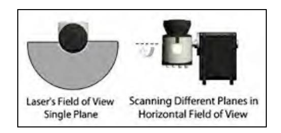
There will be a Hokuyo UTM 30LX laser rangefinder positioned in the front of the robot, scanning different planes in the horizontal field of view. The Hokuyo UTM 30LX laser rangefinder scans only a single plane in a particular position. To obtain the maximum number of data points from the environment the laser scanner will be mounted on a servo motor. The servo motor will change the orientation of the laser rangefinder which will allow it to scan a number of planes in its field of view. Figure 2 depicts the idea.
7. Sensors for Victim Identification
The different sensors which will be used for victim identification are enlisted below:
- Infrared Camera Infrared thermal imaging would be one of the primary methods of victim detection. Identified heat sources will be filtered for temperature and size before being tagged as victims. The thermal image will be relayed to the operator to be viewed. This will give the operator an idea of body temperature of the victim.
- Bumblebee Stereo Camera The images from the Bumblebee camera would be an important source of victim identification for the operator, who could then ascertain the condition of the victim. The input from the infrared camera may be combined with the color camera input to autonomously identify victims.
- CO2 Sensor A CO2 sensor located on the front of the robot will detect high concentrations of CO2. This will aid in determining the state of a victim which has already been located.
- Microphone and Speaker Once the robot is in the vicinity of the victim, the microphone could be used for communication with the operator.
8. Robot Locomotion
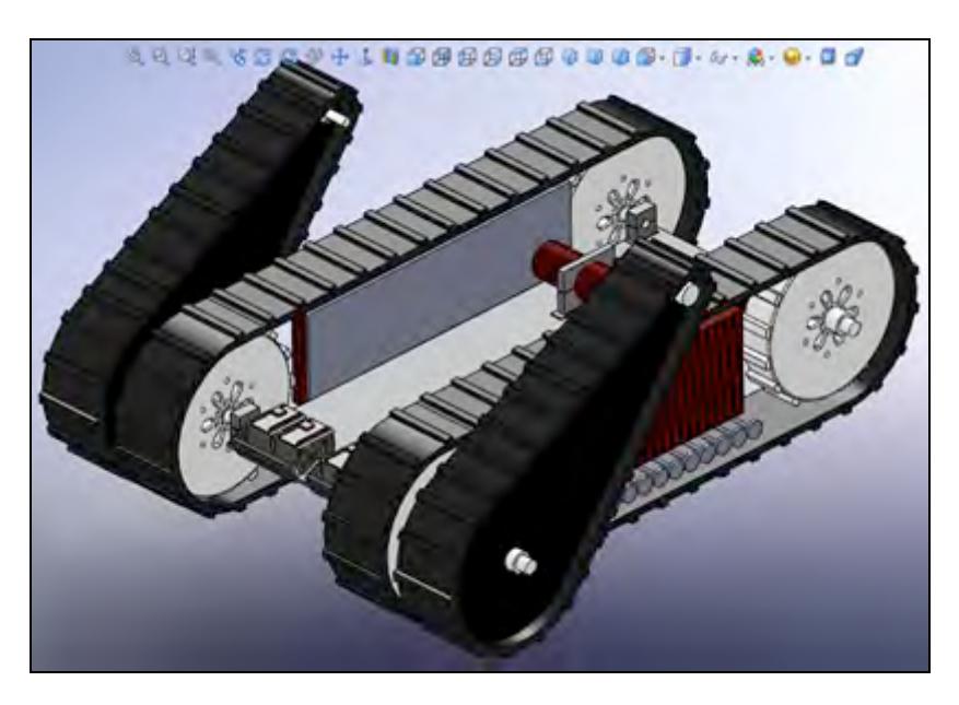
The robot will be a tracked vehicle with wide track belts. Using tracks enhances ground contact, and this significantly improves maneuverability on loose terrain (such as sand and gravel) and uneven, corrugated ground. The track system will also play a key role in stair climbing by providing the necessary grip on the surface and edges of staircases. High torque DC geared motors will drive the track system.
The proposed conceptual design is shown in Figure 3. The body consists of two parts, the main chassis and the flippers which can bend for step climbing and to easily maneuver all kinds of obstacles.
9. Other Mechanisms
For enhancing functionality, the robot would also be equipped with a cameramounted robotic arm. The robotic arm would be manually controlled by the operator for picking up objects such as water bottles, mobile phones or carrying a specific medicine to a victim. The number of degrees of freedom of the robotic arm will be decided based upon the ultimate functionality which is intended to be derived from it.
10. Team Training for Operation (Human Factors)
It will be attempted to make the user interface very easy to use and understand. The use of the Sony PlayStation Controller will make controlling the robot very natural to the operator. With a user-friendly setup it will not require more than a day of training for the operator to become adept at successfully operating the robot. With greater practice under different disaster scenarios the operator would be able to devise better strategies to extract maximum information about the disaster site.
11. Possibility for Practical Application to Real Disaster Site
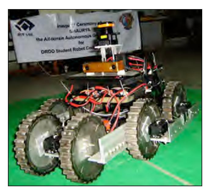
Till now we have been developing our autonomy software on a different robotic platform, indigenously fabricated by the students. Figure 4 shows a photograph of our current development platform robot. The robot which we will bring to RoboCup Rescue League is presently under fabrication. Till the competition, we would definitely be adding functionalities for robust localization, mapping and feature identification. In the competition, we hope to display a system which will be ready for actual field testing.
12. System Cost
Majority of the system components are yet to be finalized for purchase. Below is a list of components which we are already using and would also install on our future rescue robot.
System Cost
| Component | Cost |
|---|---|
| Laser Rangefinder – Hokuyo UTM-30 LX | $ 5600 |
| Colour Stereo Vision Camera – PointGrey Bumblebee2 | $ 2250 |
| Inertial Measurement Unit and GPS – Xsens MTi-G AHRS | $ 5000 |
| Laptop Computers (Two) | $ 2000 |
| Estimated Robot Chassis Cost (Materials & Fabrication) | $ 10,000 |
References
- S.Thrun, W. Burgard, and D.Fox, Probabilistic Robotics, MIT Press, 2005
- Roland Siegwart and Illah R. Nourbakhsh, Introduction to Autonomous Mobile Robots, MIT Press, 2004
- S.Thrun and others, Robotics: Science and Systems, Papers presented at the inaugural Robotics: Science and Systems conference at MIT, Cambridge, MA, June 8-11, 2005
- Ana L.C. Bazzan, Sofiane Labidi, Advances in Artificial Intelligence, SBIA, 2004, Springer
- Please visit our Website: www.teamshaurya.com.