RoboCup Rescue 2011 - Robot League Team Warwick Mobile Robotics (United Kingdom)
Jonathan Greensmith, Matthew Broxham, Matthew Dodds, Alistair Adams, Alexander Pallister, Peter Crook, Christopher Holmes, Dr. Peter Jones, Dr. Emma Rushforth
University of Warwick Coventry Warwickshire CV4 7AL; Warwick Manufacturing Group (WMG)
http://www2.warwick.ac.uk/fac/sci/eng/meng/wmr/
Abstract This Team Description Paper template is based on the Springer publication format, so please adhere to all formatting as shown. The abstract should summarize the contents of this Team Description Paper (so write it last! ) and should contain at least 70 and at most 150 words. Please edit the items in the title section above as necessary to include your Team Name, Country, Authors, Addresses, Email, and Websites. Please use the numbering scheme shown for authors from multiple organizations.
Introduction
Warwick Mobile Robotics (WMR) is an on-going student research project of the Warwick Manufacturing Group (WMG). The WMG is an institution within the University of Warwick, dedicated to improving organisational competitiveness through the application of technological innovation.
The RoboCup Rescue is an international competition that tests robots' search and rescue abilities in a simulated disaster environment. The WMR team has chosen to enter this competition as it provides not only an exciting engineering challenge, but a socially significant real world application for mobile robotics. The competition requires both a teleoperated and an autonomous machine to navigate simulated disaster zones. They are required to overcome challenging terrains, identify victims and produce a map of the environment.
This will be the fourth year of WMR's involvement in RoboCup Rescue. Last year's team won first place in the European competition, as well as retaining the best mobility title. We aim to continue this legacy of success by developing the accumulated technology and expertise of past teams, as well as the department as a whole. We aim to win our second successive European title and compete in the World RoboCup Rescue 2011 championship in Istanbul.
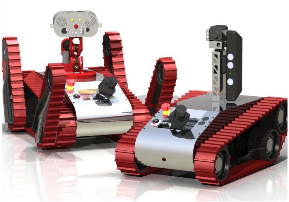
Figure 1 shows both of the robots, teleoperated on the left and autonomous robot on the right.
1. Team Members and Their Contributions
All team members have contributed to the project in a number of ways, including the technical side and the running of the project, including publicity, web design and sponsorship.
Jonathan Greensmith Mechanical Engineer
Matthew Broxham Systems Engineer
Matthew Dodds Electronics Engineer
Alistair Adams Mechanical Engineer
Alexander Pallister Manufacturing and Mechanical Engineer
Peter Crook Mechanical Engineer
Christopher Holmes Electronic Engineer
Dr. Peter Jones academic advisors
Dr. Emma Rushforth academic advisors
WMG sponsors
IMRC sponsors
Xsens sponsors
Harwin sponsors
Mouser sponsors
Thales sponsors
2. Operator Station Set-up and Break-Down (10 minutes)
The basic interface between any mobile robot and the user would take the form of a teleoperated control system to manipulate the motion of the robot. All the various motion systems would need to be controlled by a simple interface which could be modified and upgraded to suit new features as they are developed. In such an environment as to be explored by this area of mobile robotics many feedback mechanisms would need to be employed to provide the user with the required data to navigate through the terrain. Some such features might include cameras, position feedback, and independent motor control centralised into one location for easy access and interpretation.
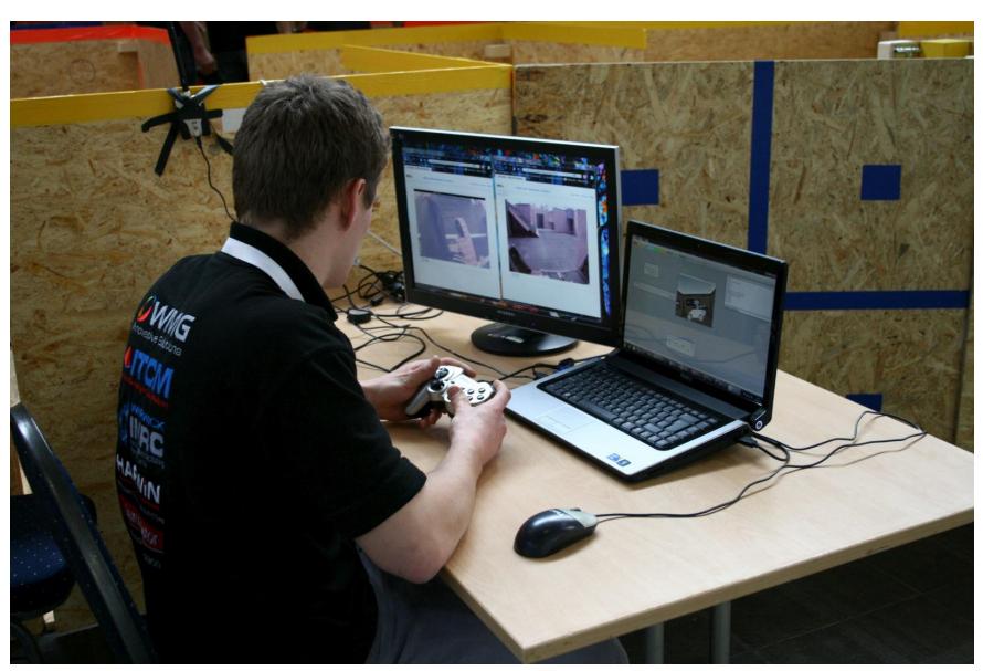
The one operator needs a laptop, with two computer monitor screens. The specific controller that will be used is a faux Playstation 2 controller. The operator will just need a table and chair with no other requirements. The system takes less than 10 minutes to set up.
The teleoperated robot and the autonomous robot will be in large cases with wheels adding to the mobility of the entire system. Figure 2 shows the easy set-up of the operation station.
3. Communications
One critical problem carried over from last year was the wireless connection between operator and robot. Main control for the robot is handled using a client-sever system with a client laptop connected over a local area network with the robot as a sever. The radio technology used meets the requirements of the RoboCup Rescue German Open where the 802.11a wireless specification is required.
The only frequency which the team uses is shown in the table below. Changes could be made for the competition following the RoboCup Rescue German Open, depending on performance. Table 1 shows the communications that can be used by the WMR robots.
Both robots use Wireless Routers that can be bought from standard technology shops.
Table 1 WMR Communications
| Frequency | Channel/Band | Power (mW) |
|---|---|---|
| 5.0 GHz - 802.11a | 6 |
4. Control Method and Human-Robot Interface
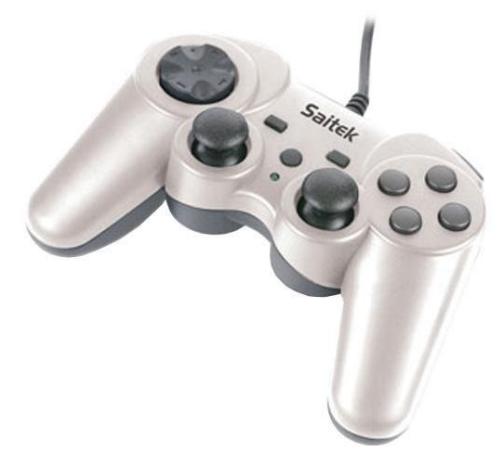
The controller that is shown below in Figure 3 is similar to the controller being used for the teleoperated robot. The controller being used is wired and does not have a wireless module.
In the current configuration, each track is controlled by one joystick for differential motion, and the D-pad and numbered buttons are used to control arm joints (allowing for pan and tilt of the head). Even without testing, it is clear that although this allows for full manoeuvrability, the movement would be slow. The arm is now controlled using inverse kinematics and a fool-proof system for control has yet to be fully explored.
The autonomous robot will be fully automated around the yellow arena and will not need any control method or human interface apart from simple controls via a ordinary laptop.
5. Map generation/printing
Our autonomous robot should have should be able to use full SLAM software that creates a real-time map of the robot's surroundings, with an accurate knowledge of the robot's position within the map. The map should be easily accessible by the current operator via a simple interface. Finally, to meet the requirements of the RoboCup Rescue rules, the final map should be automatically saved in GeoTIFF format.
The SLAM algorithm combines the processes of creating a map of an unknown environment and localising the entity within it. The SLAM algorithm combines these two processes in an iterative loop. Initially, the robot is supplied with an image of the environment from the LiDAR data. This is then used as an estimate of the environment. It then extracts the features such as walls and obstacles and uses them to determine its position in the environment.
The end result is a generated hypothesis which outlines which features it has seen before and which ones are new. Walls that have been seen before have estimates of where they were thought to have been. Using the fact that they have just been seen again, the estimate of their position can then be improved upon. This process goes through an Extended Kalman Filter (EKF) which minimizes the errors from all the sensor data consisting of the motors, compass, LiDAR and sonar data. The EKF converges the mean errors in the state estimation creating a new estimate of the positional data.
6. Sensors for Navigation and Localization
Navigation is attained on the teleoperated platform visually through the user interface. The operator will utilise both the webcam and possible the infrared cameras for navigation.
Both the teleoperated and autonomous platforms will use LiDAR to produce a 2D map of the environment. On top of this, the autonomous platform will utilise the Xbox Kinect for edge detection and 3D visual output. Sonar will also be used for detection from 0 - 0.5m at high resolution for the autonomous platform too.
7. Sensors for Victim Identification
The active sensors used for victim identification on both the teleoperated and autonomous platforms are:
- CO2 sensor using a visual CO2 level on the user interface.
- Infra-red camera for heat sensing using blob detection.
- Webcam for visual sensing.
- Microphone and speaker system for communication and sound identification of victims.
The autonomous robot has a similar sensor array but senses victims autonomously rather than using an operator to identify victims on the GUI through visual inspection.
8. Robot Locomotion
Both the robots being entered into the competition use tracked motion. The teleoperated robot uses a main set of tracks, and then four flippers, two front and two back. These flippers are powered by two separate motors.
Figure 4: Photograph of the teleoperated robot in the 2010 German RoboCup Rescue Challenge
The autonomous robot uses a main set of tracks, powered by two motor. These motors are strong enough to drag a person along a floor.
9. Other Mechanisms
The teleoperated robot uses a 5 degree of freedom arm to position and orientate its core sensor array and vision systems. This enables the operator to look into openings and over objects with the stationary robot and also can be utilised in shifting the robot's center of gravity while navigating over more challenging terrain. A gripper positioned on the end of the arm has also been developed to allow the robot to manipulate light payloads.
The teleoperated robot also implements 2 sets of additional 'flipper' tacks, one on the front and the other on the back of the robot body. Each of these can be angled independently to allow the operator to alter robot stance, weight distribution and grip characteristics while traversing the environment.
Currently the autonomous robot uses a gimble system to orientate the sensor array. This gimble system may also be implemented in the teleoperated robot, although at the time of writing this implementation is possibly going to be replaced with a rigid setup with more effective software adjustment.
10. Team Training for Operation (Human Factors)
As the robot manufacture has yet to be completed, we have yet to start our training for robot operators. However, we anticipate that the robot will require hours of practise to be able to drive the it efficiently over our stepfields and stairs.
Operation requires basic use of a controller, as outlined previously, and use of the GUI for vision. There is no dedicated training schedule for this robot.
10. Possibility for Practical Application to Real Disaster Site
The teleoperated platform is in its fourth year of testing and development and we judge that it is approaching a feasible platform for navigating a real disaster site. The new, stronger arm design this year will require some testing to assure its feasibility and effect on the mobility of the platform, as will the new user interfaces.
Currently, no detailed attention has been paid to the current standards for real world robots operating in this environment so a lot of consideration and attention will need to be paid to these to ensure true real world feasibility.
An area that definitely requires improvement for real world application is the communication systems on the robot. Significant signal attenuation through walls may render the majority of teleoperated control infeasible so more reliance may need to be placed upon the autonomous functionality.
11. System Cost
The full cost of the system is one that has been compounded over the 4 years this project has been running as the team has developed the robot each year. Every year the team has raised approximately £20,000 to go towards the development and competition and travel costs of the RoboCup Rescue.
One benefit from the project being conducted in the WMG (Warwick Manufacturing Group) is that we can take advantage of the world class manufacturing techniques within the building that do not cost the team anything. This means that some of the parts that have been manufactured for the team would be very costly for other groups to produce.
12. Lessons Learned
To be completed after the competition.