RoboCupRescue 2011 - Robot League Team iRAP_JUDY (THAILAND)
Kanjanas Saenbunsiri, Peerapon Chaimuengchuen, Nitipong Changlor, Pavonpat Skolapak, Nonthawat Danwiang, Vadidh Poosuwan, Rapeepat Tienkum, Porn-anan Raktrakulthum, Tanachon Nitisuchakul, Kanchanok Bumrungjitt, Songklod Tunsiri, Praphan Khairid, Natchapol Santi, Sai-yan Primee
Department of Production Engineering, Faculty of Engineering, King Mongkut's University of Technology North Bangkok (KMUTNB), 1518 Piboonsongkram Rd., Bangsue, Bangkok Thailand 10800
Abstract This paper describes construction and operation of iRAP_JUDY the rescue robot team that has won 1st place in Thailand rescue robot championship 2010. The iRAP_JUDY is the next generation of iRAP_Pro who has won 2 times in the 1st prize of Mix Initiative Championship Award, in World Robocup 2009 Graz, Austria and 2010 Singapore respectively. Our team has two similar high mobility teleoperative robots and one autonomous robot. The tele-operative robots have front arms which driven by caterpillar, they can identify victims very well with commodity sensors and can move autonomous in radio drop-out zone. The autonomous robot has good mobility to move up the incline surface and identify victims by using vision system with image processing and thermal sensor. The three robots are able to create map automatically. The team is prepared for difference scenarios presented in the World Robocup Rescue 2011 in Turkey.
Introduction
iRAP" is stand for "Invigorating Robot Activity Project" is team of student from King Mongkut's University of Technology North Bangkok, Thailand. "iRAP_JUDY" has won 1st place in Thailand rescue robot championship 2010. Team members are the next generation of "iRAP PRO" who has won 2 times in the 1st prize of Mix Initiative Championship Award, in World Robocup 2009 Graz, Austria and 2010 Singapore respectively. Team got special experience and knowledge from theirs.
In this paper introduce our approach to Rescue Robotics that team have been designing and developing for 3 years. Team designed 3 new robots including 2 similar tele-operative robots and 1 autonomous robot. The new robots have designed to improve problem occur from last competition and improve easiness in robots control. Our main focus is exploration all areas, detection many victims and generating a map in 2-D. The simulate situation are so many rough surface, hard terrains, rolling floor, stair, and, incline floor therefore the rescue robot should be fast enough, low weight and strong to circulate and explore while it be stable.
The designing of rescue robot in this participation is designed based on proficiency robots. Therefore team designed robot that can motivate roaming around rough terrain by using caterpillar wheel. Team designed stable cameras mounted arm on our robots and on body of robot to help identifying possible victim. Team uses the high quality motor and sensory abilities. Full sets of affordable sensors are put on to the system to measure temperature, co2, distance, to create map, and, 2-way communication. Our preliminary goal of this activity to achieve a practical rescue robot for real situation such as disaster, earthquake and, building destroy. Team expects that all the things team did can help people's life in real disaster situation.
1. Team Members and Their Contributions
The iRAP_JUDY has twelve members. The names and contribution of each member are listed as follows:
Team Members and Contributions
| Name | Contribution |
|---|---|
| Mr. Kanjanas Saenbunsiri | Controller development |
| Mr. Peerapong Chaimuengchuen | Mechanical design |
| Mr. Nitipong Changlor | Autonomous robot design |
| Mr. Pavonpat Skolapak | Tele-operative robot Hardware |
| Mr. Nonthawat Danwiang | Electronic design |
| Mr. Vadidh Poosuwan | Autonomous development |
| Mr. Rapeepat Tienkum | Mechanical and development |
| Mr. Porn-anan Raktrakulthum | Software and controller development |
| Mr. Tanachon Nitisuchakul | Controller development |
| Mr. Kanchanok Bumrungjitt | Telepoerative design |
| Mr. Songklod Tunsiri | Electronic Hardware |
| Mr. Praphan Khairid | Programing design |
| Mr. Natchapol Santi | Electronic board design |
| Mr. Sai-yan Primee | Team advisor |
2. Operator Station Set-up and Break-Down (10 minutes)
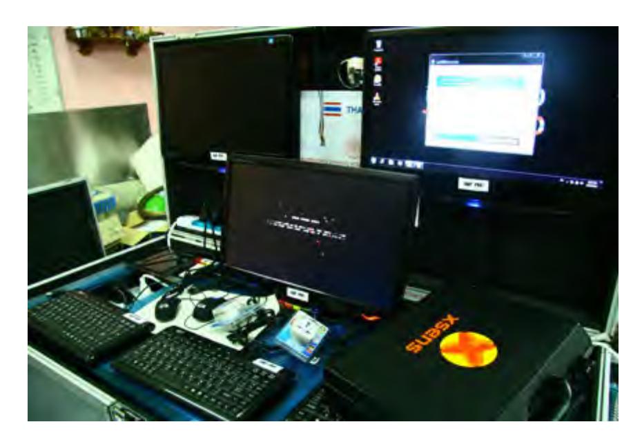
The speed of the set-up and break-down process for each task is very crucial. Team realizes that the faster for set-up and break-down can save more time for other tasks. Team uses aluminum case as the station. When needed, just open this aluminum case and turn on the switch. The operations can be started within 2 minutes. Inside this aluminum case consists of 3 monitors, notebook, access point, printer and, UPS. Once all the tasks are completed, the report and the generated map can be quickly printed out.
3. Communications
There are two communication systems used between the operator and robots. The first one is wireless LAN based on IEEE 802.11a standard which uses as the main communication system: for controlling robots, receiving video streaming from cameras on robots, and getting sensors feedback for locating the status of robots on computer monitor as well as for the automatic map generation. The second one is the RC controller with radio frequency of 72 MHz as the backup communication system for emergency situation. The range of the working distance is within 400 m for outdoor and 200 m in the building.
Rescue Robot League - iRAP_JUDY (THAILAND) Frequencies
| Frequency | Channel/Band | Power (mW) |
|---|---|---|
| 5.0 GHz - 802.11a | Adjustable | 400 |
| 72 MHz | N/A | 1,000 |
4. Control Method and Human-Robot Interface
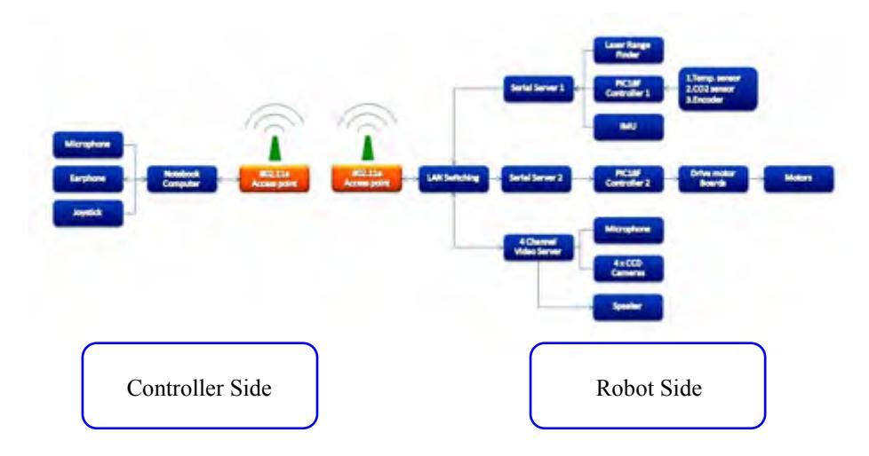
The main control is based on one CPU (PIC microcontroller 80 pins). Fig.2. is the diagram of the control system which has two main tasks as follows:
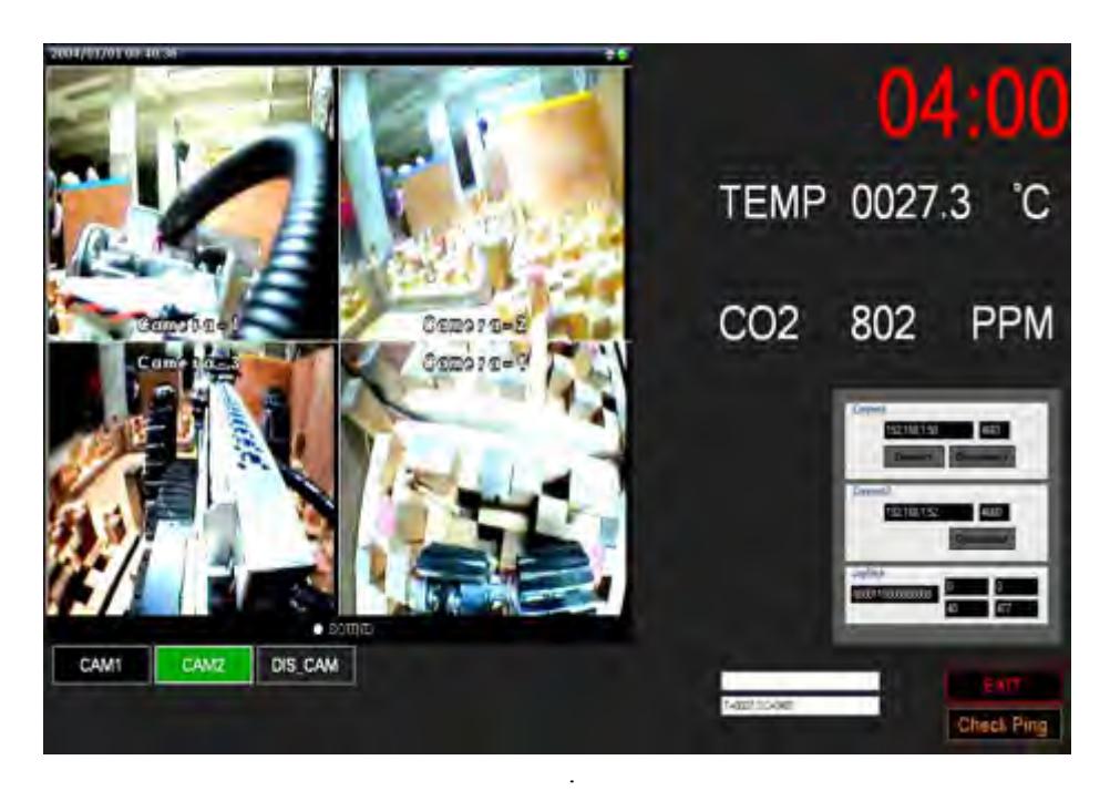
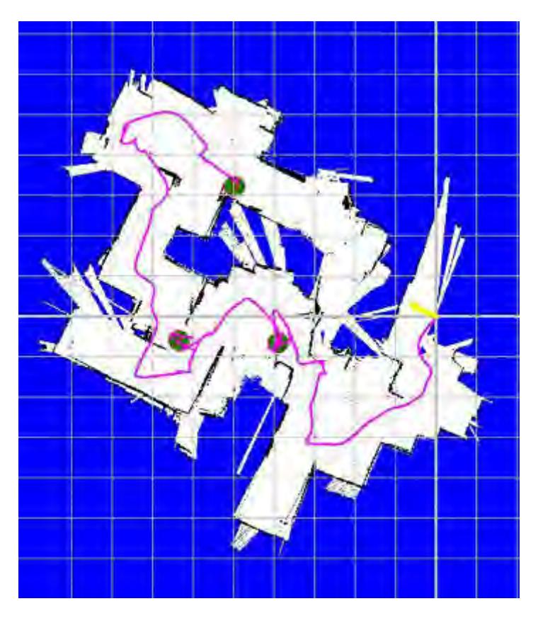
- 4.1 Used for receiving data for identifying status of the robots as shown in Fig.3. (Quad-video and sensors information) and create 2-D map automatically as shown in Fig.4. This information will be shown to the robot operator via a second computer monitor.
- 4.2 Used for sending data for controlling the movement by sending the signal to the drive control for controlling DC motor at various locations on the robots
The RS-232 communication system will be used for sending and receiving data of CPU. Therefore, there must be a serial server to convert RS-232 system to Ethernet system.
5. Map generation/printing
Several kinds of sensors are installed on each robot in order to gain the data for processing and creating automatically 2-D map on the operator's computer monitor. The map is generated by using the information from the distance the robot movement from encoders, inclination of the robot and direction of the robot sensed by Inertia Measurement Unit, and distance between the robot and obstacles from laser range finder. However, when the robot move on different kind of surface, the slipping problem can't be avoid. This slipping is major problem for designing and constructing the robot. Therefore, SLAM algorithm [1, 2] used utilized to help generate the map in addition to the information from the encoders.
6. Sensors for Navigation and Localization
Sensors, used for guiding the robot movement and identifying the location of the robots, are described as follows:
- 6.1 Encoders: Use to measure the distance that the robot moved and use this information to plot on the software along with other kind of sensors.
- 6.2 Inertia Measurement Unit [3]: Use to measure the inclination and the direction of the robot and use this data to plot along with the distance measured from the encoders.
- 6.3 Laser range finder [4]: Use to measure the distance of the obstacles in the vicinity of the robot and use this information along with data received by other kinds of sensors to generate the map.
- 6.4 Quad real time video cameras with wide-angle lens.
7. Sensors for Victim Identification
On each robot, there are four types of sensors for detecting and analyzing the victim signs by the robot. These sensors are listed as follows:
- 7.1 Infrared temperature sensor [5]: Use for detecting the temperature of victim founded for further analyzing whether the victim still alive or not. The temperature value measured by this kind of sensor will be sent back to computer and show on monitor of the operator.
- 7.2 CO2 sensor: Use for measure CO2 of victim founded for detecting breath of the victim.
- 7.3 High quality microphone and loud speaker: Use for detecting sound of the victim founded and for 2-way communication.
- 7.4 Real-time video cameras: Use for investigating of the victim founded and send video back to the operator's monitor for further analyzing the victim.
8. Robot Locomotion
Designing robot locomotion system team have been learn and improve from our team advisor "iRAP_PRO" that have many experience from many competitions. In this competition our team designed new three robots consist of two tele-operative robots and one autonomous robot. Team is looking forward to research the better of locomotion system.
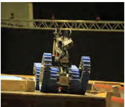
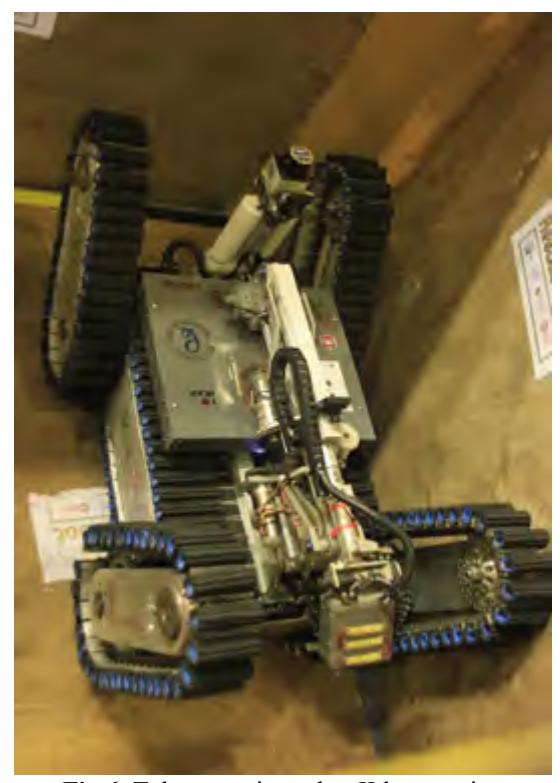
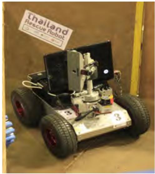
The locomotion of all tele-operative robots made of conveyer belt system that team examine from characteristic different surface of terrain. Our robot have improved many parts in order to be toughness, light weight and easy to maintenance as much as possible. Each drive system consists of two of 24V, 95 rpm DC motor with gear-boxes for the movement on the left and right. The structure of the drive system is made of aluminum. The synthetic rubber is used to make the belt. The robots have a pair of flipper that can be rotated 360 degree (as shown in fig.5. to fig.7).
9. Other Mechanisms
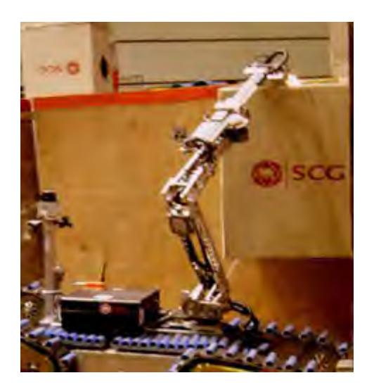
The manipulator of the robot arm which has video camera and sensors installed has high mobility. It can be rotate 360 degree and can be extended closer to the victim, if necessary, to increase visualization. Also there is gripper at the edge of this manipulator which capable of moving objects which weight less than 5 kg and can be stretched up to 1.50 m high from the floor (as shown in fig.8.).
10. Team Training for Operation (Human Factors)
The tele-operative robot requires along period for training .Team plan to perform regular competitions between our team members in order to determine the person most suitable for tele-operation. Competing members will have to build challenging arenas in order to make the current operators task more difficult.
This is our first time for world class rescue robot competition .All of us don't have many experience much but team has learned and trained from our senior "iRAP_RRO" who won 2 times in the 1st prize of Mix Initiative Championship Award, in World Robocup 2009 Graz, Austria and 2010 Singapore respectively.
11. Possibility for Practical Application to Real Disaster Site
Our main goal for this activity is used for real disaster situation. Team designed all the part of robot for real rescue application so team are confident that our robot are very useful for help disaster defender but still not for water proved.
In the future team might improve and change a lot of robot parts in the robots in order to appropriate quality for better results that may be prevent the water and fire. For example, team increase the toughness of some robot parts, weightless robot as much as possible, extending the effective range of WLAN's signal further and improve quality of video cameras. Team plans to use it in the real application soon.
12. System Cost
iRAP_JUDY has three robots. Two of which are 2 tele-operative robots and the autonomous robot. The cost of parts on each robot is listed as follows:
System Cost Breakdown
| Component | Cost |
|---|---|
| Structure of robot and drive train | $1,500 |
| Sensors - Encoders x 2 | $120 |
| Sensors - Xsense Inertia Measurement Unit | $2,800 |
| Sensors - Hokuyo laser range finder | $2,100 |
| Sensors - Temperature sensor | $350 |
| Sensors - High quality microphone | $45 |
| Sensors - Video cameras x 4 | $320 |
| Sensors - CO2 sensor | $100 |
| Controller and electronics | $350 |
| Communication system - Access point IEEE 802.11a | $180 |
| Communication system - Quad channel video server | $750 |
| Communication system - Serial server | $200 |
| Total Cost | $8,815 |
13. Lessons Learned
After competition is over, team knew how to make our robots get better. Team learned the new technology each other country from senior, learned how to be a good team. Team got many experience for this competition and the last thing team know that "The great competition cannot practicable, if you don't have the good teamwork"
References
- R. Siegwart, I, Nourbakhsh: Introduction to Autonomous Mobile Robots (2004)
- Sebastian Thrun, Dieter Fox, Wolfram Burgard: Probabilistic Robotics (1999- 2000)
- www.xsense.com
- www.hokuyo-aut.jp
- Thermalert manual Raytek Corp., Available: http://www.raytek.com