RoboCupRescue 2013 - Robot League Team CUAS RRR - Team ( Austria )
Werner Isop, Stefan Quendler, Martin Sereinig, Wolfgang Werth
Carinthian University of Applied Sciences
Abstract This paper describes the robot of the CUAS RRR - Team. The robot was designed and built for participating at the RoboCupRescue competition by a team of researchers at the Carinthian University of Applied Sciences.
In this paper the current state of the robot and the CUAS RRR - Team is described. The technical details about the communication structure, the control method and the human - robot interface are given. To make it easier for the user to navigate the robot, a graphical user interface including advanced mechanisms like virtual reality was developed. The presentation of map generation, and the sensor system for navigation, localization and victim identification is also a part of this paper. Furthermore the mechanical design and locomotion, with a special focus on the suspension system and flipper rotating mechanism is described.
Keywords: RoboCupRescue Roboter, disaster scenario, rescue operation, USB data acquisition, suspension system, brushless motors, virtual reality, head up display
1 Introduction
During a disaster scenario, for example a collapsed building after an earthquake, it is often very dangerous for human emergency forces to reach a casualty. The risk for the rescue team is reduced and the survival chances of the victims can be increased with the aid of robots. Rescue robots can be operated in dangerous areas to find victims and supply essential medicine or food. They are also capable of mapping the way through obstacles to the victims. It is also possible to equip the robot with sensors to check for risks, like existence of dangerous gases, or to mount a heat sensor to find entombed victims. Of course there are also other scenarios where human emergency forces cannot solve the rescue operation. An actual incident where robots were needed was the Fukushima Daiichi nuclear disaster. Because of the highly dangerous environment, the only way to measure the radiation exposure was to use robots.
The RoboCupRescue Senior competition is a simulated disaster scenario, in which the robots have to fulfil tasks similar to a real rescue operation. To overcome difficult obstacles is the main challenge for the mechanical design. These obstacles are for example steps, bevels with 45◦ and tubes.The difficulty of the tasks is increased each year. Therefore teams who want to be competitive have to improve the robots abilities, to solve problems which occurred at the competition and to be prepared for new competitions.
The CUAS RRR - Team was formed in 2011 in order to build a robot that is able to solve all tasks which are given by the RoboCupRescue competition. Due to the fact that this is a very ambitious goal, the project was planned from the beginning on to be separated in different phases. The first phase of the project had been designed as the development phase of the basic vehicle, which is described in this paper.
The CUAS RoboCupRescue Robot is a tracked vehicle. The main drive of the robot consists of two 200W electric motors which power a track with rubber pads. The whole drive train is suspended to accomplish an advanced mobility in difficult terrain. There are also two flipper arms, which are separately turnable by 360◦. These flipper arms are needed to overcome obstacles like stairs. The flipper tracks are driven by electric motors. As there are no robot platforms available which fulfil the requirements the whole mechanical design was done by the CUAS RRR - Team. Especially the suspension system and the flipper system are a huge advantage in mobility compared to other solutions.
Controlling the robot is basically accomplished with the help of two large subsystems. The robot remote system ('RRS') and the robot control system ('RCS'). Noticeable about the RCS is the operating system. The control system, written in C++, is running on a Windows 7 platform as a sufficient solution for fulfilling control tasks. The main computing element is an Intel i5 processor, mounted on an Mini- ATX mainboard. Furthermore the RCS interfaces with USB based hardware modules from the company Phidgets[6].
Concerning the RRS researches in terms of usability, like virtual reality and intuitive user input design are currently in progress.
2 Team Members and Their Contributions
The RoboCup Rescue Robot was designed and developed by the first team between summer 2011 and summer 2012. The team in 2013 was responsible for the building process and the first test drives of the robot. Furthermore a manipulation arm should be developed by a part of the team members in spring 2013.
Table 1. Team 2013
| Name | Role |
|---|---|
| Wolfgang Werth | Supervisor |
| Stefan Quendler | Team Leader, Mechanical design |
| Alexander Isop | Software -and electronics design |
| Martin Sereinig | Actuators and control systems |
| Martina Eberhard | Control Systems, Management |
| Christoph Unterweger | Mechanical construction |
| Kai Guggenpichler | Software, actuators |
| Dominik Schweitzer | Mechanical construction |
| Philiph Wanz | Software |
2.1 Team Summer 2012- 2013
(Team information provided in Table 1 above)
2.2 Team 2011/2012
The following table shows the team composition from 2011/2012:
Table 2. Team 2012
| Name | Role |
|---|---|
| Wolfgang Werth | Supervisor |
| Stefan Quendler | Team Leader, Mechanical design |
| Alexander Isop | Software -and electronics design |
| Martin Sereinig | Actuators and management |
| Stefan Koch | Mechanical Design and construction |
| Daniela Lingitz | Actuators and Control System |
| Georg Wurzer | Electronics |
| Martin Ringswirth | Software |
| Andra Brandtner | Sensors |
3 Operator Station Set-up and Break-Down
The remote robot control unit of the rescue robot consists of a HP Elite notebook where the remote application including the graphic user interface is running. Beside this mode of operation a virtual reality vision system and an additional input device, the joystick, are needed. The entire remote control unit can be transported and set up by a single person. The robot itself can be transported in a box with wheels. The start-up sequence is simple and the robot is ready to use in about 30 seconds after it is placed at the operation area. The connection between robot and remote system is established automatically.
4 Communications
The communication between the operator station and the robot is done throughout the "WNDR3700" router from "NETGEAR". It acts as a platform for both remote controlled and partially autonomous actions of the robot. It also supports true dual bands, offering simultaneous Wireless-N performance in both 2.4GHz and 5GHz bands. The 5GHz band is prefered basically, because of the low distribution and subsequently less utilized communication channels.
At software level the exchange of informaton is implemented via the "Winsock"- API. The data packets are transferred from the Operator station to the robot and vice versa, whereby both kind of sockets, TCP and UDP are used to establish connections in a convenient way. If it comes to videostreaming the transmission of faulty data packets or even a loss of data may be acceptable, so transmission via UDP was taken into consideration. On the other hand, if it comes to a transmission of control data, a secure and failure free connection should be guaranteed, which leads to the use of the more reliable TCP protocol. Connected to this increased transmission latencies and in average slower data throughput must be taken into account.
Table 3. Communication data
| Frequency | Channel/Band | Power (mW) |
|---|---|---|
| 2.4GHz | 802.11n | 100 |
| 5GHz | 802.11n 48(TPC) | 200 |
5 Control Method and Human-Robot Interface
Basically interaction between operator and robot is achieved throughout the use of a joystick. Further the joystick is coupled with the robot remote system ("RRS") respectively a "HP Elitebook" laptop which is connected to the robots control system via WLAN. As part of the RRS, a graphical user interface provides all necessary informations of the robots current condition to the operator. Those are e.g. live camera view for navigation but also basic status information like orientation of the robot in the plane.
In addition the operator is able to interact with the robot by using virtual reality.
5.1 Input Device
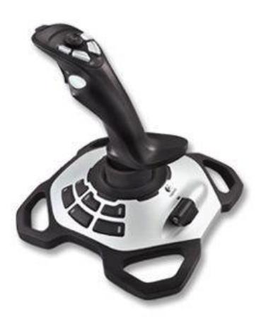
Basically the input device is represented by a "Logitech Extreme 3D pro" joystick. It owns on one hand multiple rotational and linear axis and on the other hand various buttons furnishing a powerful functional user input platform. Interfacing with the joystick is done via USB and further DirectX is used for a windows based application development. After a couple of tests, the selected joystick was evaluated as promising input device basically, although some remarks in terms of usability improvements can be stated. First of all the resisting force on the x- and y-axis might be a little bit too high. Further the scales of the axis do not reach their limits exactly when the physical stick does, so cyclic recalibration is a must. As a last remark the slider as an additional axis should be mentioned. It can be manipulated with little force only and does not own any rasterization, which makes precise operation of the axis more difficult then expected. Besides of that, an optimized mapping of the single functions to the axis and buttons involves room for improvement.
5.2 Graphical User Interface
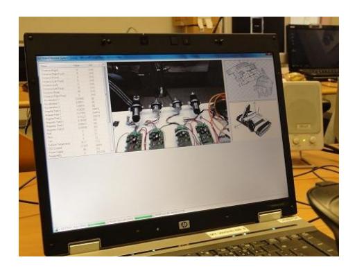
The graphical user interface is a C# based application and contains the following informations (extract):
- List of basic sensordata (e.g. power supply status, orientation in the plane, status of motor controller boards, etc.)
- Live camera stream from the robot for navigation
- 3D-View of the robot inside of the arena
- Current status/overview of acquired 2D-mapping
- Menue system for triggering shortcuts and administrative tasks
Basically it is difficult to filter and show the data, which is received from the robot, in a convenient way. Therefore, in addition to the foregrounded interface where important information is shown only, a backend with all the collected data is implemented. So the operator is able to concentrate on the most important information while controlling the robot in a conventional way. On the other hand if failures occur then it is possible investigate on the saved data where detailed status information of the robot can be extracted.
5.3 Virtual Reality
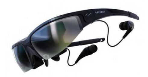
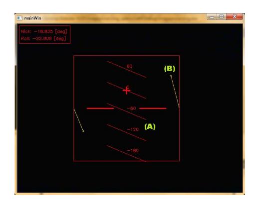
To give the operator a better impression of the current situation inside of the arena, the "VUZIX Wrap 1200" goggles are used. A stream of the robot-camera's live view into the goggles in combination with a head up display (HUD) makes important data avaiable at first sight, thus turning this advanced UI mechanism into a promising information platform. Based on concepts which are widely used in aircrafts like for example jet fighters, the following contents are planned to be implemented as part of the HUD (thereby also please refer to Figure 4.)
- HORIZON (A): The horizon basically represents the current offset NICKangle from the zero-level. This offset is live updated and scaled by horizontal lines which are drawn over constant intervals. Throughout this, the horizon is able to provide the operator with important orientation information while climbing up or moving down stairs or similar obstacles. Providing information about ROLL and PITCH-angle are taken into consideration
- FLIPPER-POSITION (B): Another important type of information, which has to be reachable as fast as possible, is the position of the flipper arms. Basically it is represented by elliptic trajectories, whereby a simple vector points to the current position.
It is noticeable that the elements which are used inside of the HUD, may seem simple at first sight. On the other hand especially this circumstance contains a lot of capabilities, because the designer is forced to accommodate information in a simple way, concurrently concentrating on most important elements only. For example, by the use of just two more mechanisms (besides of the form), color and thickness may extend the prospects of information-representation by a multiple.
6 Map generation/printing
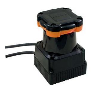
For acquiring the two dimensional mapping of the RoboCup arena, the "HOKUYO UTM-30LX" laser range finder is used (shown in Fig. 5). Because of a high scanning rate of 40Hz and a 30m scanning range at an angular resolution of 0.25◦ a high accuracy of the 2D-mapping can be achieved.
Currently the following concept is evaluated and implementation is in progress: Basically it is planned to transfer the fetched data from the laser scanner to the robot control system via USB 2.0, where it is processed in the next step. Processing the raw data includes a transformation of coordinates, filtering and a combination of the data with the spatial sensor. The result is an iterative creation of a two dimensional profile, whereby the current version of the map is sent to the robots remote system. Waypoints or points of interest in general are marked manually by the operator.
7 Sensors for Navigation and Localization
(Navigation subsection follows)
7.1 Navigation
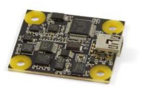
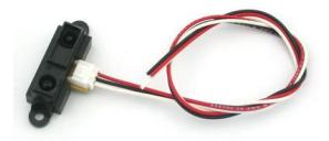
To achieve basic spatial informations, for example heading or inclination of the robot, a "Phidgets Spatial 3-3-3" inertial measurement unit is used. It interfaces with the robot control system ("RCS") via USB and has a maximum sample rate of 1000Hz. It contains all necessary sensor subsystems to acquire acceleration, angular rate and magnetic field data in three dimensions. Further the use of eight "SHARP GP2Y0A21YK0F" sensors, mounted on the outer borders of the robots corpus, is taken into consideration. The goal is to get basic distance data in the plane.
8 Sensors for Victim Identification
Due to the different areas of application many different sensors were implemented to identify and locate victims during the competitions. In future development steps some of those components will be located at the manipulation arm. At the moment those part are mounted directly on the robot.
8.1 Camera
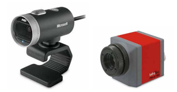
The camera is needed on one hand for the orientation in the arena and on the other hand for the victim detection. The LifeCam Cinema from Microsoft has a frame rate from 30 fps and the pictures are in HD quality with a resolution from 1280 x 720 pixel. It is used for image processing with the OpenCV library to localize special items, like victims or hazard warning signs. Further a "Infratec" thermo cam is used to acquire accurate thermographical data, making it possible to detect victims even inside of dark locations (section 8(b)).
The cam is mounted on a so called pan/tilt system (section 10) which can be moved by the head tracker of the virtual reality goggle (section 5.3) . This helps the operator to navigate the robot in the arena without moving the robot arm and gives a good overview about the current environment.
8.2 Thermo Camera
The PIR uc 180 is a USB driven thermo camera. It works in a spectral range from 7.5 µm up to 13 µm and can measure a temperature between −20◦ and 250◦C. Due to the small weight of 250g and the high security class IP65 it fits on the requested conditions.
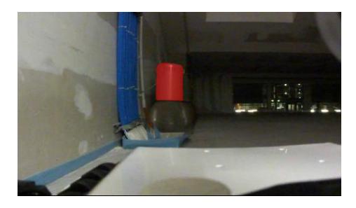
To provide the user friendliness of the whole system, the video of the thermo cam will not be displayed directly into the user interface on the virtual reality goggle. The temperature information should only be an overlay on the normal camera video if it is useful. This feature is shown in figure 9. There, as an example, the camera view from the robot is shown and the temperature of the item in red color is over a certain value. The full video of the thermo cam can be displayed by the user interface on the Operator station.
8.3 Microphone and speaker
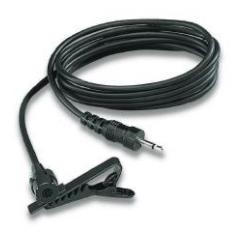
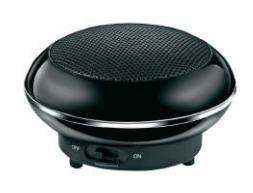
The audio communication between victims and the operator is established by software which uses the internal PC sound output and input on the robot. Thereby a amplified speaker (figure 10(b)) is connected which is loud enough to drown disturbances and noise during the communication process. A microphone is included in the Microsoft LifeCam and a separated microphone (figure 10(a)) is connected on the pc. To secure a possible communication between the victim and the operator.
The speaker is powered by the 5V channel of the USB connector and has a RMS Power of 3.8 W.
8.4 Temperature Sensor
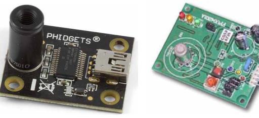
The temperature of the victims will be detected by using the 1045-0 IR Sensor from Phidgets (figure 11(a)). The temperature sensor is a non-contact infra red sensor with a range from -70C to 380C. The sensor has a field of view from 10◦ and a USB interface which allows an easy connection to the mini PC.
The temperature sensor is small enough so it can be mounted on the top of the manipulation arm (directly to the gripper) and will measure the temperature also in small holes where the victims are located.
8.5 Gas-sensor
For the CO2 detection in the air the module CDM4161A from Unitronics is used (figure 11(b)). The analog output provides an analog voltage proportional to the CO2 concentration in the air. Due to the analog output the sensor can easily be connected to one of the phidget interface kits which provide a analog input. So no additional electronic device is needed.
The sensor has an detection range of about 4,000 ppm and an update time of one second. It needs a supply voltage of 5V which can be provided by the power supply board. The operation temperature range goes from −10◦ to 40◦.
9 Robot Locomotion
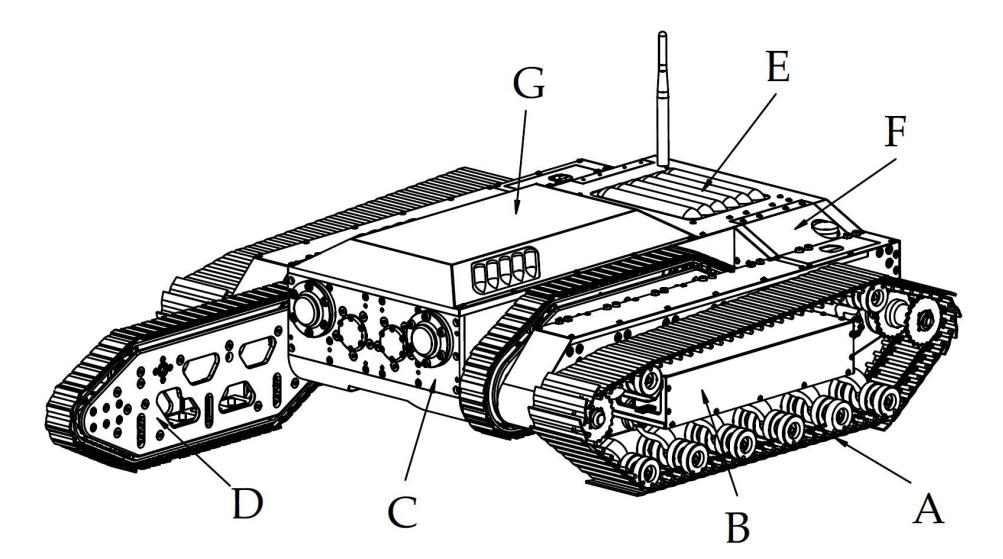
Mobility and the capability to overcome difficult obstacles is one of the base criteria for a RoboCupRescue robot. The main drive of the robot consists of two tracks, each powered by a electric motor with 200W. The main drives are marked in figure 12 by (A). To optimize the driving behaviour in uneven terrain, the drive tracks are suspended. The suspension system consists of a spring element and a shock absorber which are connected to the pivot arms. There are the rolls mounted, which guide the chain. The track itself consists of a roller chain with brackets and rubber pads which are fixed to the brackets. Because of the rubber pads the track provides a good grip on all surfaces. The suspension system in combination with the very strong and reliable roller chain improves the over all mobility in the competition, but also on grounds like rock waste or mud terrain. One of the most difficult tasks, regarding to the mobility of the robot, is the 30 cm pipe step. To overcome this pipe step, and other step-shaped obstacles, the flipper arms (D) are needed.
Most robots which use tracks as main drive system, have problems with their peak ramp angle between the tracks. This is due to the fact that there is a large area of the robot without a drive mechanism. Unlike to most other robots, the CUAS RRR has its flippers between the main tracks, and not outside. This leads to a slightly wider robot, because of the space needed for the gearbox, but the big advantage of this mechanical design is, that there is less space without a driven part. The peak ramp angle is increased, so the robot does not get stuck so easy. Each flipper arm is powered by two 70W electric motors. The flipper arms can be turned and driven separately.
The chassis is a lightweight construction out of an plastic with 30% fibre glass content. To reduce the overall weight aluminium and steel where only used when necessary because of stability reasons.
10 Other Mechanisms
Operating the robot in a complex terrain is a very difficult task, mostly because of the limited view. For a better usability and controllability a swinging mechanism for the camera and the thermo camera is planned. This pan tilt system has two axis, which allow rotating and tilting of the cameras. The user controls the mechanism with the help of the virtual reality goggles. A inertial sensor provides the data, where the head of the user is moving, and the pan tilt system follows this direction.
A RoboCupRescue Robot has to have a manipulation arm to reach victims in higher positions, move items and to fulfil the shoring task. This task is about building an supporting structure around a pole. However, the development of this manipulation arm is in progress, and some concepts of how to solve the given tasks in a proper way are already finished. On the manipulation arm the camera and its swinging mechanism is mounted. The work on the manipulation arm will be finished in July 2013.
11 Team Training for Operation (Human Factors)
An operator of the robot has to have a good eye hand coordination. But due to the fact that user friendliness is an essential requirement for the project the basic control of the robot has to be very easy. The virtual reality goggles as mentioned in section 5.3 helps to get a good feeling for the robot locomotion. The pan/tilt system is moved directly by the movement of the operators head, respectively by the movement of the reality goggles. Nevertheless a long term training is required to overcome difficult terrain and obstacles. The navigation of the robot is made by a joystick as mentioned in section 5, this includes the main drive, the flipper rotation and the flipper drive mechanism. An important facilitation for the operator is that just one input device is used. This allows the operator to focus on one device to control the robot.
To get used into the robot operation first no special test environment is needed. But to be best prepared for the competition a special test arena will be constructed. The team is also in contact with other Austrian teams, this are the University of Applied Sciences Upper Austria and the Graz University of Technology. Those universities also have some different test arenas which will be used to improve the controlling skills of the operator.
12 Possibility for Practical Application to Real Disaster Site
During the construction process the team was always searching for informations from different real world applications in the rescue area. It was the idea to take and combine existing systems and to improve them.
Since the project start in Summer 2011 the focus was not only to build up a robot for the RoboCupRescue competition, it was also suggested to be able to move the robot in natural environment. In near future the robot will also be tested in different environments like scrap yards, ballasted areas and in forests. During the summer the robot also will be introduced to different rescue parties, and tested by members of rescue teams (e.g. some firemen) to get some additional feedback. This should help to improve the skills in real disaster scenarios.
13 System Cost
The arrangement shown in table 4 presents the main cost of the robot. Additionally many parts of the robot e.g. some axis of the gear box or some parts of the suspension system were manufactured at the mechanical work shop of the Carinthian University of Applied Sciences. Those costs are not included in the following table.
Table 4. System Cost
| Part | Supplier | Unit price [Euro] | Units | Total price [Euro] |
|---|---|---|---|---|
| Robot production | Meislitzer Präzisionstechnik GmbH | 12000 | 1 | 12000 |
| Actuators (motor, gear, encoder) | Maxon Motor AG | 475 | 6 | 2850 |
| Controller Boards | Maxon Motor AG | 160 | 6 | 960 |
| I/O Module | Phidgets | 100 | 10 | 1000 |
| Power Supply Unit | Conrad, RS Components, Schweighofer, Farnell | 790 | 1 | 790 |
| Accumulators 37V | CMC | 430 | 2 | 860 |
| Accumulators 14.8V | CMC | 225 | 1 | 225 |
| Control system, PC | cartft, Alternate | 1000 | 1 | 1000 |
| Machine Elements | Filli, Altmann, Styr Werner | 2000 | 1 | 2000 |
| Sensors | Phidgets, Ultrasonic | 450 | 1 | 450 |
| 2D Laser Scanner | NO DNA | 3800 | 1 | 3800 |
| Thermocamera uc180 | InfraTec | 4700 | 1 | 4700 |
| Operator Notebook | HP | 1800 | 1 | 1800 |
| Router | Netgear, Conrad | 150 | 1 | 150 |
| Total | 32585 |
14 Lessons learned
After visiting the "RoboCup German Open 2012" in Magdeburg Germany, many impressions from the live competition scenario could be collected to improve ideas and concepts for a later assembly of our robot. Also, in between the action, some useful information could be gained directly from the participants of the RoboCup teams. In the following the most important thoughts should be mentioned in a short way.
14.1 Wireless network connection
After watching some teams dealing with broken down connections and high network latencies during the cup, this topic received best attention during the later progress of the robot project. As there did not exist any experience with the situation on site, soon it became clear that performance and reliability of the wireless connection between the robot and the operator are very important points. Subsequently the more modern 802.11n standard in combination with the higher 5GHz frequency band was basically taken into consideration.
14.2 Computing power
As there already exists a great variety of interesting tasks which could be fulfilled as part of the RoboCup and therefore also contain complex solutions and algorithms. So available capacity in computing power is very important. Further, with respect to upcoming interesting topics, like 3D profiling with a KINECT sensor, or artificial intelligence and autonomous navigation, the demands on the processing unit(s) may even get more important in the near future.
References
[1] HOKUYU: HOKUYU UTM-30LX. http://www.hokuyo-aut.jp/ 02sensor/07scanner/utm_30lx.html, 2013. – [Online; accessed 06- Jannuar-2013] [2] Isop, Alexander: Entwicklung und Implementation der zentralen Steuerungs-Applikation für einen "RoboCup Rescue" Roboter, Carinthia University of Applied Sciences, Bachelorarbeit, 2012 [3] Koch, Stefan: Entwicklung, Analyse & Realisierunge eines Hilfsantriebes für einen mobilen Such- & Rettungsroboter, Carinthia University of Applied Sciences, Bachelorarbeit, 2012 [4] Lingitz, Daniela: Modellierung und Regelung der Aktorik eines RoboCup Rescue Roboters, Carinthia University of Applied Sciences, Bachelorarbeit, 2012 [5] Meislitzer: Meislitzer Präzisionstechnik GMBH. http://www. meislitzer.at/, 2013. – [Online; accessed 06-Jannuar-2013] [6] Phidgets: Phidgets, Products for USB Sensing and Control. http://www. phidgets.com/, 2013. – [Online; accessed 06-Jannuar-2013] [7] Quendler, Stefan: Konzept eines RoboCup Rescue Roboters, Carinthia University of Applied Sciences, Bachelorarbeit, 2011 [8] Quendler, Stefan: Entwicklung des Fahrwerks für einen RoboCup Rescue Roboter, Carinthia University of Applied Sciences, Bachelorarbeit, 2012 [9] Ringswirth, Martin: Entwicklung einer grafischen Benutzeroberfläche für einen Rescue-Roboter, Carinthia University of Applied Sciences, Bachelorarbeit, 2012 [10] Sereinig, Martin: Aktorwahl, Modellierung und Regelung des Fahrverhaltens eines Roboters zum Einsatz im RoboCup Rescue Senior Wettbewerb, Carinthia University of Applied Sciences, Bachelorarbeit, 2012 [11] Wurzer, Georg: Energieversorgungseinheit für einen Rettungsroboter, Carinthia University of Applied Sciences, Bachelorarbeit, 2012