RoboCupRescue 2013 - Robot League Team PANDORA (Greece)
Vassilios Petridis, Zoe Doulgeri, Loukas Petrou, Andreas Symeonidis, Charalambos Dimoulas
Department of Electrical and Computer Engineering Aristotle University of Thessaloniki
http://www.ee.auth.gr/ · http://www.robocup.org
Abstract Within the context of the 2013 RoboCup-Rescue competition (www.robocup.org) the PANDORA Robotics Team of the Aristotle University of Thessaloniki has developed an experimental robotic platform for area exploration and victim identification. Our robot is able to autonomously navigate itself through unknown space (e.g. building ruins from an earthquake), avoid obstacles, and search for signs of life and identify victims. We are going to use one tracked platform aiming at identifying victims residing in the yellow arena and assisting victims in the blue arena (grasping and carrying a specific object, such as a small bottle of water). This is the TDP of the PANDORA robot.
Introduction
The PANDORA Robotics Team (Program for the Advancement of Non Directed Operating Robotic Agents) of the Department of Electrical and Computer Engineering (DECE) of Aristotle University of Thessaloniki (AUTH), Greece aims in developing an experimental robotic platform for indoor exploration and victim identification. Overall objectives of the team are the application of the existing know-how on a reallife problem, the advancement of the group's state-of-the-art expertise. The PANDORA Robotics Team was founded in 2005 and has already participated in the RoboCupRescue 2008, 2009 and 2011 competitions. This year, the team intents to participate in the yellow and blue arenas.
1 Team Members and Their Contributions
The team comprises 5 faculty members of varying expertise and a compilation of postgraduate and undergraduate students. The following list provides the names and responsibilities of the team members.
Team Mentors
- Vassilios Petridis, Professor
- Zoe Doulgeri, Professor
- Loukas Petrou, Associate Professor
- Andreas Symeonidis, Lecturer
- Charalampos Dimoulas, Lecturer
AI Team
Team Leader: Emmanouil Tsardoulias
SLAM: Aris Thallas, Dimitrios Tatsis, Nikos Tsakiridis
Navigation: Giorgos Gkioulis, Christos Zalidis Data Fusion: Christos Zalidis, Giorgos Gkioulis
Planner: Aris Thallas
Software Architecture Team
Team Leader: Triantafillos Afouras
Testing: Nasia Irodotou, Aspa Karanasiou, Nikos Gountas
Simulation: Nick Pehlivanidis, Aggeliki Kargopoulou, Anna Minou
GUI: Christos Zalidis
Vision Team
Team Leader: Alexios Papadopoulos
Face recognition: Alexandros Papadopoulos
Tag/Hole/Motion detection: Linta-Lamprini Koletsou-Koutsiou, Despoina Paschalidou
Voice recognition Team
Sound control: Pavlos Chatzoudis
Electronic design Team
Team leader: Charalampos Serenis
Sensors: Dimitrios Kanlis, Konstantinos Tsourapas, Michalis Niarchos
Motors: Antonis Pappas, Anna-Maria Tirovouzi
Integration: Panagiota Vakoula
RoboArm Team
Team Leader: Ilias Sedikos
Arm Kinematics: Vangelis Apostolidis
Arm Gripper: Ilias Sedikos
Logistics, Support
Athina Anoixiadou
The team is going to be represented by 11 members in the competition. Names are going to be listed in the registration form.
2 Operator Station Set-Up and Break-Down (10 minutes)
Three operators are needed for setting up the PANDORA robot: the head operator of the system, who carries the base station case, and two operators that carry the platform case.
The initialization process is realized as follows:
- Transfer all objects in the area and deploy (3 minutes).
- Activate the platform and the base station (3 minutes).
- Launch the PANDORA robot OS (2 minutes).
- Perform communication check, in order to establish and validate Wi-Fi connection (1 minute).
- Perform system check and diagnostics, in order to verify that all the systems of the platform are working properly (1 minute).
3 Communications
Following RCR regulations, we are going to use W-LAN 802.11a (5 GHz) and will wait to be assigned with a channel/band from the organizers during the competition.
Table 1. PANDORA communication protocol
| Rescue Robot League | ||
|---|---|---|
| PANDORA (GREECE) | ||
| Frequency | Channel/Band | Power (mW) |
| 5.0 GHz - 802.11a | 100 |
4 Control Method and Human-Robot Interface
The PANDORA robot will operate in two modes: the fully autonomous mode, where a number of simultaneous processes will be executed in order to achieve autonomous exploration and victim identification, and the tele-operation mode, where the robot will be totally manipulated by an experienced user.
In order to ensure a flexible and modular scheme where reconfiguration is possible, we opted for a component-based software architecture. The selected architecture ensures easy testing and integration, while it decouples the overall system from each component's actual implementation.
4.1 PANDORA Software Architecture
All state-of-the-art middleware provide an infrastructure for building custom applications, while providing tools to support robot software development. Apart from the above, middleware added-value relates to major non-functional requirements they ensure, such as real-time (or near real-time) performance, reliability and security. From the plethora of existing approaches, though, not many satisfy the above criteria.
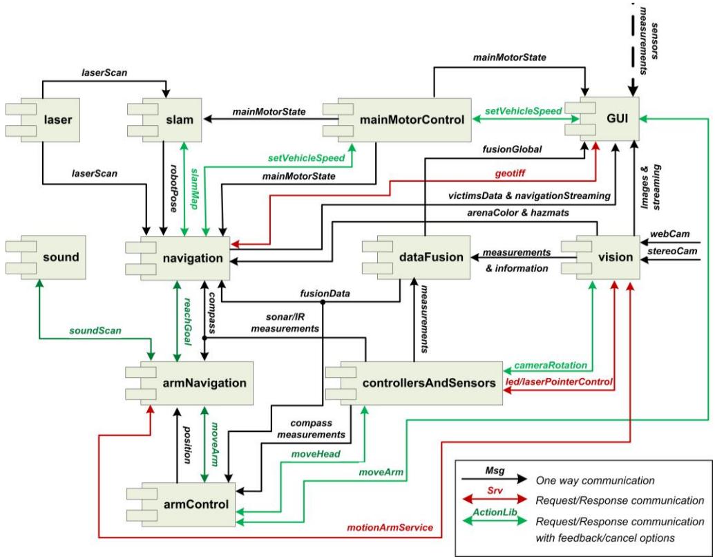
Having considered various off-the-shelf middleware (including MSRS,OROCOS and ROS), we adopted ROS [ROS] http://www.ros.org/ for PANDORA's middleware. A number of factors were considered during the middleware selection process. A messaging communication scheme was preferred to a typical RPC-style middleware, due to its inherent ability to promote loose coupling. Furthermore, messaging provides asynchronous communications with the ability to control dataflow, which is extremely important for complex interconnected systems. Among others, the basic advantages of ROS are: open-source nature, transparent architecture, wide-spread usage, interoperability with other robot frameworks, quality of the development toolchain and extensive documentation.
ROS comprises a peer-to-peer network of components (denoted as nodes), which communicate via messages through the respective ROS infrastructure. The channels that messages are sent through are called topics. RPC-style communication is also achieved through services and data persistence is achieved through the Parameter Server.
4.2 PANDORA Graphical User Interface (GUI)
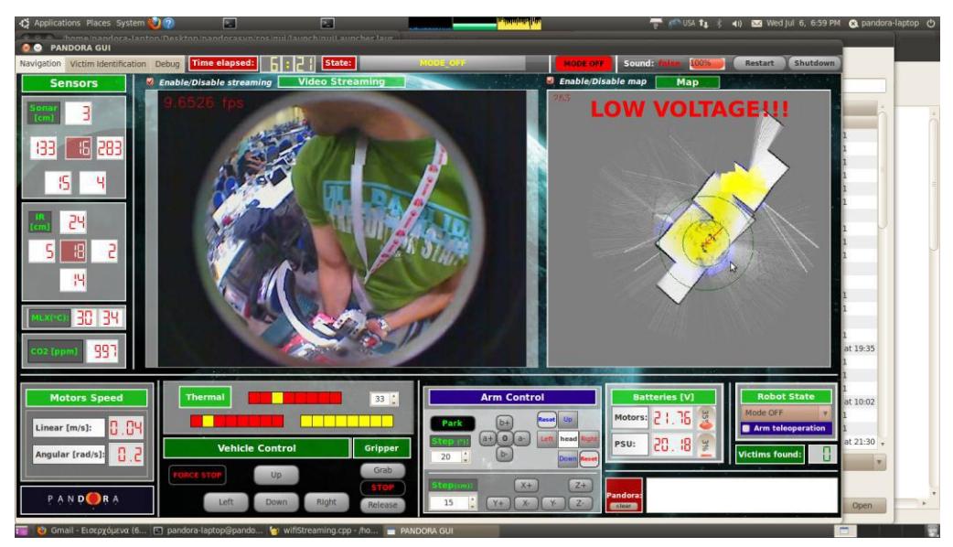
PANDORA provides a user friendly GUI for visualizing information and operating the robot. Three tabs are available, containing information related to navigation, victim identification and debugging. In each of the tabs, related information is displayed, as depicted in Table 2. Nevertheless, the operator can dynamically add/remove sensor information and modify the type and the layout of the widgets displayed in each tab, since PANDORA GUI adopts a widget-like architecture. A mockup of the GUI is provided in Figure 2.
Table 2. Information displayed in the respective GUI tabs
| PANDORA GUI | ||
|---|---|---|
| Navigation Tab | Victim identification | Debugging Tab |
| Tab | ||
| Map | Map | Map |
| Web camera streaming | Coverage | Web camera streaming |
| Operating mode | Voronoi diagram | Stereo vision camera streaming |
| Temperature reading | Victims number | Motors speed |
| Distance from Sonar | Victims places | Current robot position |
| sensors | ||
| Distance from IR sensors | Goals | Sensors status |
| CO2 measurement reading | Path to current goal | Temperature reading |
| Noise source direction | Noise source | Compass bearing |
| direction | ||
| Compass bearing | Distance from Sonar sensors | |
| Robot angle state | Distance from IR sensors | |
| Platform inclination on | CO2 quantity reading | |
| rear and side view | Noise source direction | |
| Wi-Fi signal strength | ||
| Battery level |
When on tele-operation mode, the robot vehicle is controlled using a wired gamepad or a keyboard, while the robot arm is controlled using a joystick. When on the autonomous mode, GUI is only for visualizing/monitoring and no intervention is allowed, up to the point that a victim is recognized. Then, PANDORA sends an interrupt signal to activate the GUI and expects proper operator action in order to continue.
4.3 PANDORA Hardware Architecture
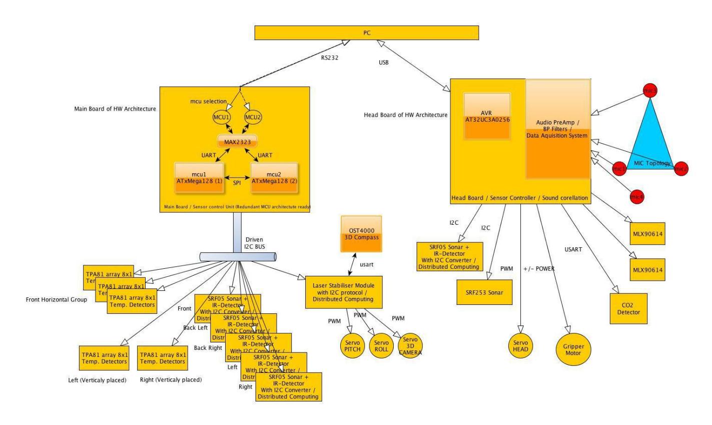
Figure 3 provides an overview of the hardware needed to interface with the various sensors of the system. The platform is equipped with two sets of sensors, the first one is responsible for localization and navigation procedures, while the second one for victim identification.Two PCBs have been built, the Main Board and the Head Board.
The Main Board communicates with the sensors mounted on the main chassis i.e. the distance sensors (ultrasonic and infrared) and thermal sensors and controls the servos of the LRF stabilizer. The I2C communication protocol is employed. This option reduces the wiring, facilitates the expansion of the sensor subsystem and simplifies the software development. The employment of I2C-bus drivers / buffers allows the removal of noise introduced into the bus system. Thus a dynamic and scalable system has been developed that provides the interconnection of up to 127 sensors. Communication error handling algorithms have been developed to ensure error free data acquisition.
5 Map generation/printing
(continued below)
5.1 SLAM
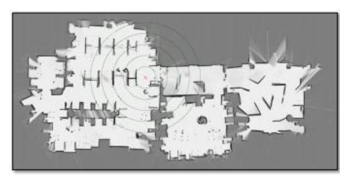
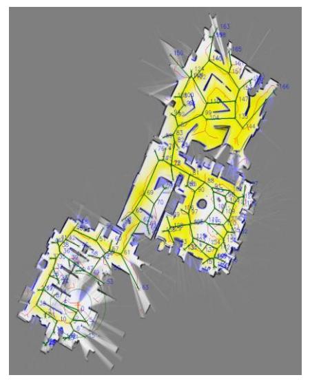
PANDORA implements a CRSM (Critical Rays Scan Matching) SLAM scheme for space exploration [2]. It employs an occupancy grid map and performs a scan-to-map match, instead of the traditional scan-to-scan matching. Scan matching is realized through a genetic like algorithm mechanism (Random Restart Hill Climbing) and ray reduction is employed for performance reasons.
One of the two most important features of CRSM SLAM is ray-picking; the main idea is to reduce complexity and time needed for matching by preprocessing the scan and selecting rays that are "critical" for the matching process. We define "critical" in the sense that the remaining ray information is redundant to the matching process, since the "critical" scans act as features of the scan, even if they are extracted from heuristics and not from any feature extraction method. A hill climbing mechanism has been adopted for the identification of the correct transformation between the current scan and the global map (which is the inverse of the robot translation and rotation). Hill climbing is a very popular and efficient method for finding optimal solutions to complex problems. Its setup is like a genetic algorithm but the population consists only of one individual.
The individual genome in the genetic method comprises three numeric values (<Dx, Dy, Dtheta>), representing the correct transformation for scan matching. The fitness value for the individual is calculated by summing the possibilities of occupancy in the selected laser rays, according to the transformation of the hill climbing individual.
5.2 Navigation
PANDORA's navigation module comprises three sub-modules: the Path Planner, the Navigator and the Streamer.
The Path Planner is the coordinator of the robot's computational intelligence. It monitors all other PANDORA nodes, providing them with input and allowing them to take control and perform specific tasks. It defines a goal (target) in the environment according to the circumstances, creates the path to it, and feeds the navigator in order to follow it. Also, it (de)activates the camera, sound and arm navigation nodes (subsystems).
5.3 Data fusion
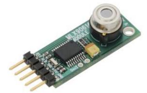
The Data Fusion module is responsible for filtering out the messages generated by PANDORA sensors (CO2, MLX thermal sensor, TPA thermal sensor, sound module and camera). It stores a set of thresholds of all sensors, which are the possibility values of an eligible valid measurement. Given that a sensor measurement exceeds the threshold, Data Fusion informs the Path Planner with details. One should mention that thresholds are not hard-coded and are not crisp; rather, a flexible mechanism has been implemented so that the Path Planner is informed if a sensor has an almost "valid" value. Messages communicated by Data Fusion abide by a predefined uniform format, containing the sensor type, the probability of a measurement to be valid, and its direction, in case the sensor is directional.
6 Sensors for Navigation and Localization
The PANDORA robotic platform is equipped with several sensors in order to determine its current position and its distance from various objects. These sensors are discussed next.
6.1 Laser Range Finder (Hokuyo URG-04LX)
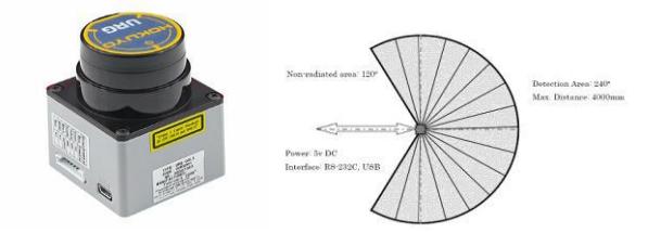
For map creation a Hokuyo URG-04LX Laser Range Finder (Figure 6) has been installed. It has a viewing angle of 240° and a detection range of 20mm up to 4m. The angular resolution is 0.36°, which gives 667 measurements in a single scan, while its linear resolution is 1mm. Measurement accuracy varies from 10mm (for distances from 20mm to 1m) to 1% of the measurement for distances up to 4m (Fig. 6). It operates on 5V DC (possible error of +/- 5%) and has a current consumption of 500mA.
6.2 Ultrasonic Sensors
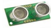
Five ultrasonic SRF05 sensors (Figure 7) are situated around the robot. They communicate via the I2C bus with a microprocessor, publishing a pulse with width proportional to the distance of the object. Their power consumption is very low (approx. 0.02W). In the front part of the vehicle they will be used to prevent the vehicle from bumping on obstacles. SRF05 sensors have a detection range of 3cm to 4m and will be used as a complement to the Laser Sensor.
6.3 Infrared Sensors
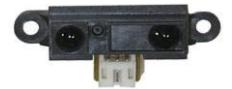
Infrared sensors are placed both on the left and on the right side of the robot and they will cooperate with the ultrasonic sensors in order to give an accurate measurement of the distance of the robot from any obstacle. GP2Y0A21YK (Figure 8) infrared sensors were selected. Their detection distance range is small (10 cm – 80cm), thus they are assigned with monitoring the close surroundings of the robot. One of the sensors is assigned to measure the distance between the bottom side of the robot and the ground, so as to fire an alarm in case the robot is in danger of falling.
7 Sensors for Victim Identification
In order to accurately identify a victim and pinpoint his/her location, a number of sensors have been installed, providing input to sophisticated detection algorithms. Specifically, a stereo vision camera, thermal sensors, a CO2 sensor and four microphones are being used. Sensor results are then fused to determine the behavior of the robot.
7.1 Vision
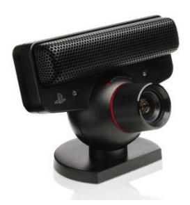
The autonomous platform is equipped with a stereo vision camera of custom design, based on two Sony's Playstation Eye cameras (Fig.9) on stereo configuration and a standard web camera to offer the requested set of detection and identification services. Furthermore, stereo vision processing enhances PANDORA's ability to calculate distance from the victim.
7.2 Temperature
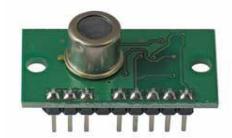
We consider that temperature differences in the environment could imply victims. Thus we have installed Focal Plane Array (FPA) thermal sensors, in order to compare temperature values, find fluctuations and make an estimate of a victim's position, if one is found. The TPA81 (Figure 10) is a thermopile array (thermocouples connected in series), together with a silicon lens and associated electronics, which detects infrared in the 2um-22um range (the range of radiant heat). It can measure the temperature of 8 adjacent points, as well as the ambient temperature, simultaneously. It can detect victim's temperature within 2 meters and its typical field of view is 41˚ by 6. It is connected to the Main Board via an I2C interface and updates its values at a rate of approximately 20Hz. The TPA81 are mounted on top of the stabilizer module and on both sides of the robot.
7.3 CO2 sensor
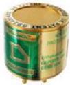
The CO₂ sensor (Figure 12) measures the concentration of CO₂ gas in the environment. For the detection of the human respiration, we simply track fluctuations in the concentration of CO₂ in the air. The selected sensor can detect concentration of CO₂ gas, from 0 – 50,000ppm.
7.4 Sound
Pandora's voice processing unit comprises the following components:
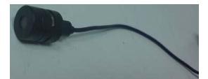
- Four electret-cardioid microphones (Figure 13) located on the head of the robotic arm. All the four microphones are placed at the same level (considered to be the z=0 plane) and position, forming a coincident microphone array. Thus, the principal pick-up axes (main directivity vectors) form a cross shape, with each pair of successive microphones having an angular main axis distance of 90° . In geometrical terms, each microphone points on one of the four distinct directions +x (1,0,0), +y(0,1,0), -x(-1,0,0), -y(0,-1,-0) of the Cartesian XYZ axes-coordinates.
- One amplifier with four channels, one for each microphone.
- One analog band-pass filter per microphone.
- One DAS with four inputs with sample and hold, in order to achieve simultaneous recordings, one Analog to Digital converter, and digital filters.
- One Atmel AVR AT32UC3 microcontroller mounted on the Head Board.
PANDORA Voice node is assigned with two tasks: to find a victim and identify its state. In exploration mode, Voice scans the space in order to grasp a sound that could direct to a victim. Upon the identification of a sound, a request is sent for thorough scan. If granted permission, Voice performs a second scan and provides Data Fusion with an estimate of the position of the victim, as well as a level of certainty of the estimation. When the vehicle approaches the victim and the robotic arm extends to approach him/her, Voice is assigned with the task to recognize his/her state. To do so, Voice measures the volume of the sound, transforming it to dB. Then, the estimate of the state of the victim, as well as a level of certainty of the estimation is sent to Data Fusion.
8 Robot Locomotion
(continued below)
8.1 Platform mechanical design
The PANDORA vehicle employs an improved track system for its locomotion. The basic improvements are as follows:
- the use of a tensioner mechanism for the synthetic track
- the adjustment of idle rollers, so as to avoid track oscillations and damage
The metal frame of the robot is made of aluminum. The platform is equipped with two 50W brushless DC motors with a reduction planetary gearhead. The size of the robot is 560x230x200 mm. It is solid enough, appropriate to move in different types of terrain and climb easily a 40° slope.
9 Other Mechanisms
(continued below)
9.1 Robotic Arm
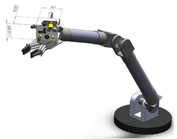
The PANDORA Robotic Arm was designed in order to provide the ability to reach most of the points of interest. The geometry selected led to a five degrees of freedom robotic arm, with rotational joints and cylindrical links as shown in Figure 14.
Cabling issues specified link diameter. Joints are designed to allow folding of the arm and maximize angle limits in order to achieve optimal system workspace. Joints are powered by dc motor-encoder-reduction gearbox assemblies connected to appropriate drivers for control implementation. Joints are monitored by external optical or magnetic encoders so as to determine the absolute position of the arm and thus avoid recalibration hazards due to power loss. The head of the arm accommodates all essential sensors for victim identification and partly for navigation. The Robotic Arm is equipped with a gripper attached at the end of its fourth link for object manipulation. The gripper uses traction and smart construction so as to make optimal use of its four degrees of freedom based movement and orientation.
Solutions for direct and inverse kinematics are incorporated in the arm's software. Different types of trajectories, such as linear or along the approaching vector have been implemented covering the range of required motions. Other kinematic calculations are also made related to the reachability of target points and the location of the arm's center of mass for a specific configuration and ground inclination to avoid vehicle turnover.
9.2 Stabilizer
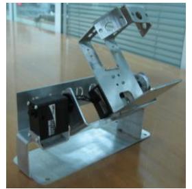
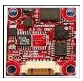
The stabilization mechanism (Figure 15) is mounted on the chassis of the robotic platform. It allows the laser, the thermal sensors and the stereo vision camera to stay on the horizontal level, regardless of the robot's inclination. The stabilization is achieved via two linear DC-servomotors with fast response using a three dimensional Ocean Server's OS5000 compass, which gives measurements in degrees (Figure 16). It provides the inclination of the robot with respect to the starting inclination. The compass communicates with the Main Board, through UART protocol. The compass is also used to stabilize the laser of the robot at the desired position. Its accuracy is not higher than 0.5 degrees with 0.2 degrees resolution. Its refresh rate is at 40 Hz.
9.3 Computing System (Single Board Computer)
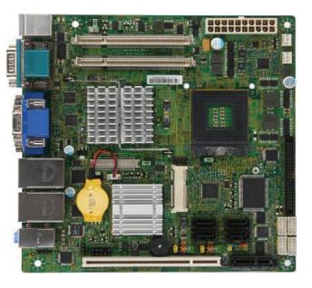
In order to accommodate the processing needs of PANDORA, we employ a Mini-ITX system (Figure 17) placed it in the main body of the robot. The specifications of the system are the following: ibase MI953F mainboard, Mini-ITX, Socket G1 (988), Intel QM57 Express Chipsatz, Intel i7-840QM Mobile Processor, 4GB of DDR2 SO-DIMMs, a Solid State Drive with 32GB capacity, all power from a M4-ATX Pico PSU. The board's dimensions are 17x17cm and for peripheral interconnection there are 8 USB ports, 5 RS-232 serial ports, a PCI FireWire, and a MiniPCIe WiFi capable add-on card with 2 pigtails for external antennas. The system power consumption is estimated at 80Watts at full computing load, without the USB, Serial and FireWire peripherals connected.
Communication between the single board computer (SBC) and the sensor network is performed through a serial interface. The higher level protocol designed allows strict timings and deterministic prediction of the CPU load generated by the sensors. This allows PANDORA to operate almost in real time.
10 Team Training for Operation (Human Factors)
The operator(s) should be familiar with the GUI and the gamepad. He/she should be able to understand the readings of all sensors and act accordingly when allowed. He/she should go through extensive training and accomplish test missions in the specially constructed arena, which emulates a destruction scene.
11 Possibility for Practical Application to Real Disaster Site
The fully deployed robotic platform has not been tested in a real environment yet. Nevertheless, the previous platform was exhibited at EXPO 2008 in Thessaloniki, and it was widely accepted. The Hellenic Rescue Team and the Institute of Engineering Seismology and Earthquake Engineering showed vivid interest in the potential of using the platform in real life. Additionally, we are planning to develop a similar platform with a local company for surveillance purposes.
12 System Cost
The following table provides information on the cost of the parts of the PANDORA platform.
Table 3. Part names, quantities and cost
| Part Name | Quantity | Price (€) | Website |
|---|---|---|---|
| Mobile Platform | 1 | 4000 | Custom made |
| Arm | 1 | 2000 | Custom made |
| Platform Motors and Controllers | 2 | 1500 | http://www.maxonmotor.com |
| Arm motors and Controllers | 5 | 4400 | http://www.maxonmotor.com |
| http://www.hitecrcd.com | |||
| Laser sensor | 1 | 2300 | www.active-robots.com |
| Single Board Computer | 1 | 850 | http://www.mini-tft.de |
| Sensors | 20 | 1150 | http://www.active-robots.com |
| Stereo vision camera | 1 | 150 | http://www.scei.co.jp/ |
| CO2 sensor | 1 | 200 | http://www.dynament.com |
| compass | 1 | 250 | http://www.ocean-server.com |
| Microcontrollers | 4 | 300 | http://www.atmel.com |
| Touch screen | 1 | 100 | http://www.olimex.com |
| Batteries | 2 | 800 | http://www.hoelleinshop.com |
| Cabling and connectors | 1000 | ||
| TOTAL | 19000 |
References
- Quigley, M., Gerkey, B., Conley, K. , Faust, J., Foote, T., Leibs, J., Berger, E. , Wheeler, R. , Ng, A.:ROS: an open-source Robot Operating System, in ICRA Workshop on Open Source Software. (2009)
- Tsardoulias, E. Petrou, L.: Critical Rays Scan Match SLAM. J Intell Robot Syst. DOI 10.1007/s10846-012-9811-5. Published online on 9 Feb. (2013)
- Russell, S.J., Norvig, P.: Artificial Intelligence: A Modern Approach. 2nd edn. Upper Saddle River, New Jersey: Prentice Hall. (2003)
- Nidhi Kalra, N., Ferguson, D., Stentz, A.: Incremental reconstruction of generalized Voronoi diagrams on grids, Robotics and Autonomous Systems 57. 123-128. (2009)
- Dijkstra, E.W.: A note on two problems in connection with graphs, Numerische Mathematik 1. 269-271. (1959)
- WillowGarage: OpenCV 2.1 C++ Reference. Available online at: http://opencv.willowgarage.com/documentation/cpp/index.html
- Szeliski, R.: Computer Vision: Algorithms and Applications, ISBN 1868- 0941, Springer (2011)
- Belhumeur, P. N., Hespanha, J., Kriegman, D.: Eigenfaces vs. Fisherfaces: Recognition Using Class Specific Linear Projection. IEEE Transactions on Pattern Analysis and Machine Intelligence 19, 7. 711-720. (1997)
- Joly, A., Buisson, O.: Logo retrieval with a contrario visual query expansion. In:MM '09: Proceedings of the seventeen ACM international conference on Multimedia, New York, NY, USA, ACM. 581-584. (2009)
- Joly A., Buisson O.: A Posteriori Multi-Probe Locality Sensitive Hashing, MM'08, October 26-31. 209-218. (2008)
- Lowe, D.: Distinctive image features from scale-invariant keypoint, International Journal of Computer Vision, 60, 2. 91-110. (2004)