RoboCupRescue 2013 - Robot League Team Yıldız (Turkey)
Sırma Yavuz, M. Fatih Amasyalı, Erkan Uslu, Hamza Osman İlhan, Alper Eğitmen, Jamal Esenkanova, Okan Yıldıran
Yıldız Teknik Üniversitesi Computer Engineering Department, Davutpaşa, İstanbul TR34220 Turkey
http://www.robotics.yildiz.edu.tr/
Abstract This paper describes the improvements on robots, their operation and strategies developed by Team Yıldız. Since our last appearance in RoboCup Championship in İstanbul, team has decided to concentrate on full autonomy. This was the result of experiences gained during the competition in 2011 and Safety, Security and Rescue Robotics (SSRR) Summer School in 2012. The team especially worked on efficient navigation and victim detection strategies. Team will participate in German Open competitions and depending on the capabilities of the developed robots; one or two wheeled robots will be used during the championship.
Introduction
Team Yıldız (previously named Team Barbaros) is part of the robotics research group founded within the Computer Engineering Department of Yıldız Technical University. Our group is working on mapping, autonomous navigation and image processing algorithms and developing its own autonomous mobile robots since 2007 [1, 2]. The group is focused on developing search and rescue robots and the algorithms required in search and rescue operations. Two teams working with real robots and with simulation environment has emerged from the research group. Both of the teams work closely to develop algorithms and join RoboCup competitions since 2011. The real robot team was not able to join the competitions in 2012, mainly because of financial reasons but the virtual robot team won the second place in Mexico world championship. Real robot team contains one undergraduate and four graduate students apart from the two academics who act as team leader and advisor. Members of the team have a strong background in programming, electronic and mechanical design. Contributing towards the production of robust and more intelligent search and rescue robots is the most important goal of the group.
We are planning to use two different robots during the competition. Both of our robots are wheeled models and suitable for autonomous navigation. This is an improved model of our previous robot PARS [3, 4]. For the competition, our original model gone under some modifications; such as resizing, adding suspension, incorporating new sensors and changing the location and number of sensors.
1. Team Members and Their Contributions
The list of the team members and their main responsibilities are as follows:
- Sırma Yavuz Advisor, also responsible of mechanical design, electronics and SLAM software development
- M. Fatih Amasyalı Advisor, also responsible of victim detection and image processing software development
- Erkan Uslu Electronics, controller programming
- Hamza Osman İlhan SLAM software development, Control interface design
- Alper Eğitmen Electronics, Communication infrastructure Jamal Esenkanova Navigation Algorithm, ROS support
- Okan Yıldıran Image processing software, victim detection
2. Operator Station Set-up and Break-Down (10 minutes)
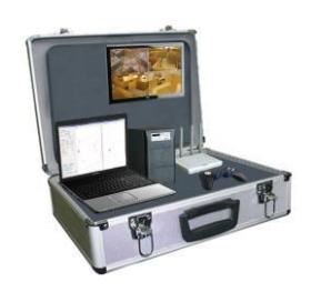
An aluminum wheeled case as shown in Fig.1 will be used to carry all necessary items for the operator station. The station will be powered up and powered down with one button. The operation case contains one laptop, one lcd monitor one portable printer, one gamepad, one access point and a power unit. To carry the robots we plan to use a movable chassis with wheels, it is constructed according to the size of our robots. Although other team members will assist the operator to carry the operation case we aim to have only one operator to set up and break-down the operator station within 10 minutes. Two people will be responsible of carrying the robots inside and outside the competition arena.
3. Communications
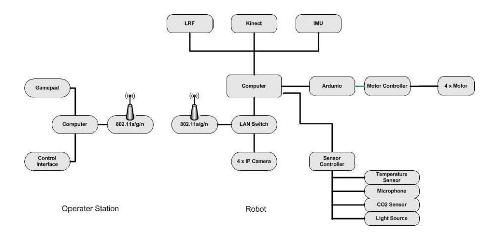
There are two access points in our system, one on the robot side and the other on the operator station. These access points support 802.11a/n and 802.11g/n; however we plan to use 802.11g/n to communicate between our main robot and the operator station. The computer used on our robots supports 802.11a/n and 802.11g/n will be connected to the access point via Ethernet cable. General setup of our system is shown in Fig. 2. The wireless communication is between the access points require a selectable 802.11a/n or 802.11g/n band. There is a headset to be used by the operator requiring Bluetooth communication.
Table 1. Communication requirements of the team
| Rescue Robot League | ||
|---|---|---|
| YILDIZ (TURKEY) |
||
| Frequency | Channel/Band | Power (mW) |
| 5.0 GHz - 802.11a | 32mW | |
| 2.4 GHz - 802.11g | 32mW | |
| 2.4 GHz - Bluetooth | spread-spectrum |
4. Control Method and Human-Robot Interface
Although the team will have two robots; only one robot will be used per mission. Both of the robots are fully autonomous. It will try to cover the most of the area using SLAM algorithms relying on sensor data and will generate the map of the area automatically. Victim detection is planned to be fully autonomous as well. The robot will only send the necessary information to the operator's computer for him to annotate and print the victim information and the map.
For both of the robots algorithms will run on the robots and only the automatically generated maps and video streams will be sent to the operator's computer. There will be simple interface where operator fallows the sensor based map generated by the SLAM algorithm and may eliminate points he considered to be faulty, he will also see the position of the robot as calculated by the SLAM algorithm. One part of the screen will show the video streams from Kinect while the other part shows the position of the robot according the IMU data. Normally operator is able to command the robot using a gamepad for urgent situations but we plan not to use that option during the competition.
Basically, operator will be only watching the screen during operation and printing the map at the end.
5. Map generation/printing
Since our last appearance in the competition, we have started to use ROS framework which allowed us to use various tools and libraries. Recently we started to use Hector Mapping software [5] to generate a 2-D map of the environment. We made some modifications to the software to determine the positions of the robots or victims. And we will be using our own navigation software which requires data from both victim detection and mapping algorithms. Operator can follow the landmarks and victims found by the algorithm on the screen. We will extend the software, to provide an information sheet for each victim found, to allow operator to edit the victim information. Operator will be able to print the victim information and the final map using the print button on the software.
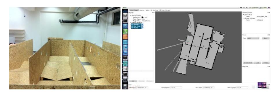
We are able to produce reliable sensor-based maps using FastSlam and EKF Slam algorithms [6, 7], but they are not fully adapted into ROS yet. A sample sensor-based map generated in our laboratory, using Hector SLAM is given in Fig. 3. Our previous work on SLAM algorithms primarily rely on LRF and encoder data for mapping and localization. Since the competition site is more complicated, including ramps, stairs or holes on the walls we are currently incorporating IMU and Kinect data into our software. In our application we aim the operator to add few annotations to the information sheet provided by the software and not to interfere with automatic map generation at all.
6. Sensors for Navigation and Localization
- Inertia Measurement Unit (IMU): It provides 3D orientation, acceleration, 3D rate of turn and 3D earth-magnetic field data.
- Laser Range Finder (LRF): The field-of-view for this sensor is 240 degrees and the angular resolution is ~0.36 degrees. It can measure distances from 20mm to 4 meters.
- Ultrasonic Range Finders: Although these sensors are not crucial for mapping or localization, they are used to sense any obstacles close to the ground and are not detectable by LRF.
- RGB-D Camera (Kinect): Our navigation algorithm uses Kinect data to head towards the possible victims. Although, the Kinect data is not originally used as a part of the localization software, we intent to use it to correct the IMU data in future to increase the reliability in real disaster areas.
7. Sensors for Victim Identification
- RGB-D Camera (Kinect): We primarily relay on RGB-D data to identify any possible victims. While depth information provides information to identify possible victims, RGB data is used to confirm the presence of victims.
- Thermal Array Sensor: Measures the absolute temperature of 8 adjacent points in its field-of-view simultaneously. Number of sensors is located on the robot at different heights.
- CO₂ Sensor: It is used to check the breathing for the victim found.
- Microphone and speaker: These are used to detect the sound of the victim.
8. Robot Locomotion
For the competition, our original model gone under number of modifications; during the process different types of models are produced. The final model which is under construction is a four-wheeled model having passive suspension system.
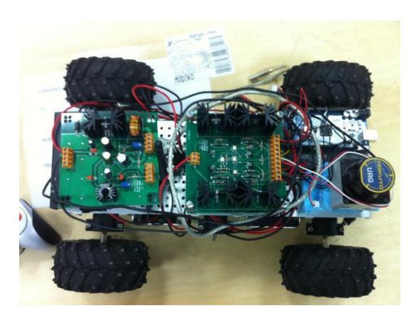
At the moment our team uses two robots. The robot shown in Fig. 4 is a six-wheeled, relatively small model and basically is used to develop algorithms.
9. Other Mechanisms
Migrating to ROS and aiming only full autonomy has changed the mechanisms considerably. In terms of mechanics, we have decided to use only wheeled models and no tracked robot for this year. We have experimented on passive and active suspension systems and decided on a simpler suspension which will allow us to cover most of the area without experiencing too many mechanical problems. ROS allowed us to make use of drivers for Ardunio platform. Now we use Ardunio platform to receive input from our sensors and to control the motors. We have also started to use Kinect sensor for victim identification, which has libraries available for ROS. In terms of navigation strategies, changes in sensors and full autonomy made our algorithm more reliable and faster. We have also built an arena very similar to the competition in our laboratory to test the algorithms.
10. Team Training for Operation (Human Factors)
All members of our team are trained to have basic knowledge in using ROS to be able to develop their algorithms in this platform. Although, it is relatively simple to get our robots running, it took some time to build a platform for them to notify each other from the developments, so every one of them will know what to do to run the robots without having problems. We have documented the steps required to run the robot and it is updated regularly. The team still needs some time to finalize their work and experience in the arena which has built in our laboratory. We expect to test our system fully in German Open competitions.
Since the robots run autonomously, no extensive training of the operator, but to make sure the set-up and break-down procedures to be completed in time and the operator can evaluate the results produced by the robot correctly or make any annotations when needed, there he still needs to be trained.
11. Possibility for Practical Application to Real Disaster Site
On a real disaster site, the main advantage of our system is being able to move autonomously. Communication would arise as an important problem in most disaster sites. If the robot is not able to get back where it has started, the information it gathered inside the ruins becomes completely useless. Although we still have a long way to go in terms of mechanics, the strongest feature of our system is its autonomy. In terms of mechanical design, we are working on a design that can cope with rough terrain better, besides having financial problems we will probably need much more work to be successful on a real and completely unknown disaster site.
12. System Cost
Please use this section to total the costs of key system components and the overall expense of your system.
System Cost
| Name | Brand - Model | Web |
| Robot Base | ||
| Electronics for motor control and sensor readings | Arduino Uno, Motor Driver shield | http://www.arduino.cc/ |
| Motor | 2KE-2032 Series | http://www.zhengke.cn |
| IMU | Xsens 6 dof IMU | http://www.xsens.com |
| LRF - Laser Range Finder | URG-04LX | http://www.hokuyo-aut.jp |
| Access Point | Airties | http://www.airties.com |
| Kinect RGB-D Camera | Microsoft | http://www.xbox.com/en-US/kinect |
| Computer | ||
| CO2 sensor | MG811 for Arduino | http://www.arduino.cc/ |
| Thermopile | Devantech TPA81 8x1 Thermopile | http://www.acroname.com |
| Ultrasonic | Devantech SRF08 | http://www.acroname.com |
| Battery | Li-Po | |
| TOTAL PRICE = Approximately $15000 |
13. Lessons Learned
After our first competition the main conclusion we draw was " we had to see it to really understand it". It was a great experience in many ways:
- We realized that very simple mistakes or not having enough training time may finish the run at the first moment,
- We had a chance to get to know each other far more better under the pressure and tried to establish the team accordingly,
- We realized that we have aimed much more than what we can achieve for the first time; trying to have different kind of robots caused us not being good enough at anything. For that reason, this time we have decided to concentrate on full autonomy and work on other aspects such as manipulation in future. Going step by step is proven to be important.
- We have had the disadvantage of working on the algorithms up to the last moment and did not run the robots on areas similar to the competition site. As a result, on the set-up day we realized that our wheeled-robot was too close to the ground which prevents it to move even in a simple ramp. Also for the tracked robot, we only realized an electronic design mistake after burning few motor controller cards, when robot got stuck. Now we have an arena where we constantly try our robots.
References
- Thrun, S., Burgard, W. and Fox D.: Probabilistic Robotics, The MIT Press, Cambridge, Massachusetts (2005)
- Kurt Z., "Development of Intelligent SLAM Algorithms, Master Thesis, Yıldız Teknik Üniv., (2007)
- Özışık O., Yavuz S.: Fuzzy-Neural Robot Controller for Unknown Environment Exploration, 1st International Fuzzy Systems Symposium (FUZZYSS09), Ankara (2009)
- Şahin O., Yavuz S.: Autonomous Parallel Parking Robot, International Symposium on Innovations in Intelligent Systems and Applications (INISTA 2009), Trabzon (2009)
- Thorsten Graber T., Kohlbrecher S, Meyer J., Petersen K., Stryk O., Klingauf U.: Team Description Paper RoboCup Rescue League Team Hector Darmstadt, Mexico (2012)
- Özışık O.:Simultaneous Localization and Mapping with Robot Team, Master Thesis, Yıldız Teknik Üniv., (2010)
- Özışık O., Yavuz S.: An Occupancy Grid Based SLAM Method", IEEE Computational Intelligence for Measurement Systems and Applications (CIMSA 2008), İstanbul (2008)
- Bay H., Tuytelaars T., Van Gool L.: SURF: Speeded Up Robust Features, ECCV 2006, (2006)