RoboCup Rescue 2019 Team Description Paper ATR Team
Xiangxu Lin, Irvin Cardenas, Nate Kanyok, Alfred Shaker, Pavan Poudel, HyunJae Jeong, Nadia Karina, Jared Butcher, Jong-Hoon Kim, Gokarna P. Sharma
Kent State University
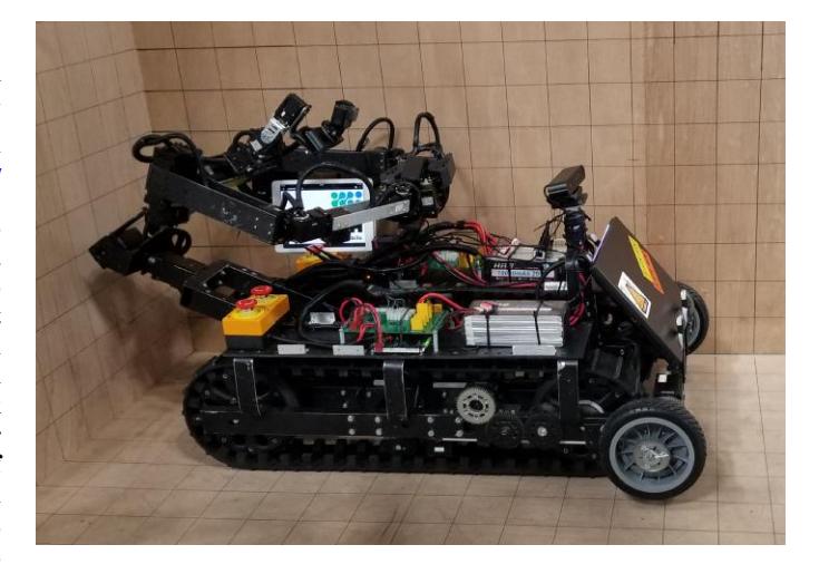
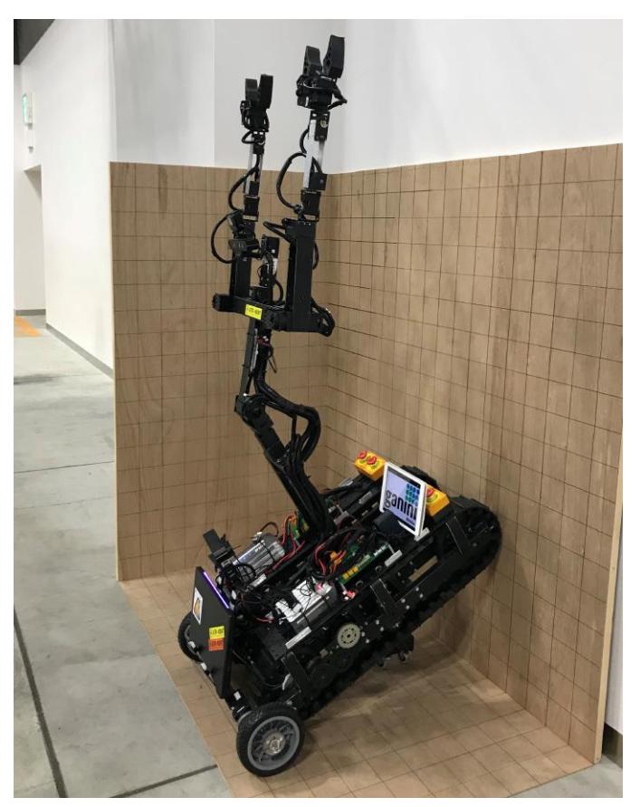
Abstract This paper describes a mobile robot called "TeleBot-2" with an immersive, embedded control system. TeleBot-2 is a special design for search and rescue task by Advanced Telerobotics Research (ATR) Laboratory at Kent State University. It is a transformable telepresence humanoid robot. It can switch between the folding tank mode and upright stand operation mode. During the folding tank mode, the robot is able to shrink its size to minimum while maintain basic operation function for lower terrain operation by folding in the top, humanoid half of itself. When it switched to upright stand operation mode, it will release the full function and skill set of humanoid upper body. It also gives it the advantage of operating objects at high places.
In this paper, we are not only competing for the RoboCup Rescue League competition, but also proposing a modern approach for every robotics lover to kick start in robotics filed.
Index Terms—RoboCup Rescue, Team Description Paper, Tele-Operative, Virtual Reality, Robot System
I. INTRODUCTION
THE notion of telepresence and teleoperation is not science fiction anymore. People are using it in their daily life for applications such as video chat, which is a simple version of telepresence. Remote PC control can be treated as teleoperation to help others fix some problem they are facing on their PC. Because of the physical limit we all human being shared that we only have one body and we can not teleport to different places. We need a robot to do a certain job that we are not able to or one that is too risky to do, such as run into a nuclear facilities to save victims or operate some machine at high radiation environment.
In this paper, we present the TeleBot-2, which is built on our previous work to bring a more immersive, intuitive and robust telerobotics system to life. TeleBot-2 is a transformable telepresence semi-autonomous robot. It can switch between folding tank mode for minimum size and upright stand operation mode for advanced operate function. The key advances of our robot includes: (1) transformable, which can fit into different terrain and perform different types of jobs; (2) Virtual Reality (VR) control system, which give user the immersive and easy control interface compare to transitional button control system; (3) sophisticated algorithm for manipulation and path planning, which enable precise control and autonomous feature; (4) robust robotics system structure, which ensures we cover every aspect from robot development to real life operation.
II. SYSTEM DESCRIPTION
The robot system can be broken into two parts, software and hardware. In terms of the software, we use Robot Operating System (ROS) as our base operating system frame, and add virtual reality (VR) control mechanism on top of that. On the hardware side, we are using dynamixel motors as our main control motor, iron plate as robot's bones and drone as third eyes of Telebot2.
A. Hardware
In this section, we will describe the details of robot's physical structure.
1) electric circuit
Due to the complexity of electric flow inside the robot system, and safety concern of things in general, we design our own PCB board to handle and exchange power inside our system.
2) Leveling Platform
We are deploy two IMU modules on both the head and mobile base of the robot. For the mobile base one, we will get both roll and pitch rotation to balance out robot when it drive through uneven terrain in case too much weight falls into only one side of robot and flip the robot. In terms of the one installed on head, it will be used to get all roll, pitch and yaw information to smooth the head movement and stabilize the video steam we get from robot to prevent operator getting dizziness from watch tremble video feed.
3) Mobile Base
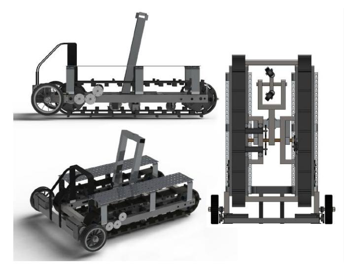
The mobile base contains the heart of our robot, the electronic boards, core computing PC, emergency button, battery and radio for transmitting video signal between robot and operator. All would be implemented on the mobile base. as terms of driving function, we have two type of driving mode, one is using tank driving mode, which we implement by using 2 tank track with dynamixel Pro motor and the other one is three wheel differential drive mode as show in fig 4, which we implement by having two wheel in front and use one dynamixel Pro motor in the center of the mobile base, and push the third wheel down to ground to rise up the robot base and body in order to transform as show in fig 2. and we also implement a Astra depth sensor camera on the front side of mobile base to generate 3d point cloud and needed 2d mapping information for path planning and manipulation.
4) Upper Body
For the upper body of our robot, we are using combination of dynamixel Pro and dynamixel XM540- W270 for 9 degree of freedom (DOF) arms and two dynamixel Pro as waist to assemble our robot upper body to give operator a human-like operation platform which allow operator to have more precise as well as more immersive control of the robot. and we also implement multiple camera on robot as needed to give operator a better view of what is happening on robot side and avoid collision between surrounding object.
5) head
In the head unit of our robot, we implement another Astra depth sensor camera to generate another set of point cloud and combine with the mobile base one to have more detail and clear data. and we also attach a Go Pro camera on top of Astra depth sensor to get real-time video feed with 0.2 sec of latency.
6) Drone
As for done, we bought the original parrot drone from market and implement our own algorithm to make it follow and hovering on top of Telebot2, using octomap to build 3D map for better localization and to give us a God view of the scene to help operator to make better judgement choices,
B. Software
In this section, we will demonstrate what our software structure looks like, the navigation algorithm and how we implement our control system for TeleBot-2.
1) main frame
The core of our software structure is based on Robot Operating System (ROS), it is a robotics middleware which designed for heterogeneous computer cluster. it provides the communication between different device, low level control of hardware, implementation of commonly used functionality and so on. it is one of the main stream robotics control system nowadays.
2) driving system
For driving system, we implement our own method based on turtlebot3 driving system. it uses differential drive mechanism on both form of our robot, and it can be transform base on operators' need.
3) drone system
The drone is controlled by aircraft path planning software that utilizes the P4X [1] open source software package for controlling drones with MAVLink and ROS The drone can be fed direction on the fly or set on a pr.-planned course. P4X provides tools for collision detection and gathering sensor data which will be useful main robot manipulation.
4) navigation
Our approach for navigation is let ground robot using rtabmap ros [2] package to create a 3d point cloud of surrounding environment and create a 2D occupancy grid map for navigation. as for the drone part, we implement octomap to create a 2D map as well to correspond with rtabmap to get a more accurate localization. and we also stream video from attached camera on drone to have live video feed to operator.
5) object detection
For object detection, we have various of detection. Such as using OpenCV for rusty detection to check if we need to replace some components or not, or keep track of moving object for position update, or using you only look once (YOLO) [3] algorithm to detect surrounding object or victims and so on. All object detection methods can be used base on the need.
C. Communication
We are using two communication method between robot and operator, one is for transmitting video signal from robot to operator with S-4914T/R wireless HD transmission system, and the other is using networks access point which compliant with IEEE 802.11a 5 GHz standard to sending rest necessary data, such as general video feed, robot control command, mapping data and so on.
D. Human-Robot Interface
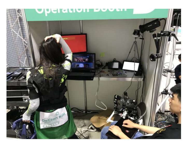
As human-robot interface show in Fig. 3, we break down into 3 parts as follow: (1)visual control, (2)robot manipulation (3)training steps.
1) visual control
As terms of visual control, we have 2 different interface for main operator and support operator. for main operator, we are using HTC VIVE Pro Virtual Reality headset which provide main operator an immerse view of what robot is watching, get a better understanding of what next move should be. Inside the main operator view, we have different icon indicate the status of robot such as overheated, overloaded, connection interrupted, etc. And a small skeleton of robot project robots movement in the field. we also have a small windows flow on the top-right corner showing the image capture by the front camera of headset indicate what is happening inside the operation room, main operator has the ability to switch between two different view. And for support operator, we have transitional 2D webcam view coming from multiple camera of both Telebot2 and drone. support operator can base on those video feed to better assist main operator to complete task.
2) robot manipulation
For robot manipulation, there are two parts to it. First is upper body manipulation, which we currently have 3 different type of control system, (1).Telesuit control, (2).Mannequin control and (3).PC GUI control. our main control system is using Tele-suit control, which is a custom made sport wear suit embedded with multiple imu sensor to track operator's movement, and project it to robot. With the power of VR headset, operator will have the true feeling of "I am the robot" in order to simplify or complete task what traditional robot control system can not complete or hard to complete. Mannequin control system is a extended control mechanism from Tele-suit control, we use the idea of "project human movement" into a mannequin robot, operator can use their hand to manipulate a small size mannequin robot, and project the movement of small robot to big one. this is a safety controller system in case of imu on telesuit malfunctionthen we can use mannequin control to take over. and the last one is PC GUI control system which is simple button, slider based control system which runs on support operator's PC as the ultimate safety control in case everything else fails. Second is driving control, which we have two different interface, first one is using the controller from HTC VIVE Pro for main operator, and the other is using PC GUI interface for support operator.
III. APPLICATION
A. Set-up and Break-Down
For our robot, since we are gonna use VR control system to control the robot, and robot itself is too heavy for one person to carry, so we will have one people use a spare laptop to connect to ROS master running on robot and using keyboard to drive robot into Venue, and main operator carry VR ready laptop to Designate place start setting VR station. after everything setup, operator will communicate with robot though network. this would usually take 7 to 15 mins to finish. as for robot itself, it already has battery mount on it which can last 2 hours of maximum performs. After finish, it will be the same that one person with laptop use keyboard control to drive robot back to base. and one person will start dissemble VR station which will only take up to 10 mins.
B. Mission Strategy
As we describe earlier on the paper that we are planning on use two robot, one is ground robot for operate equipment and navigation. one is drone robot for provide better view to operator and check environment when ground robot is not at the position to do so. and as terms of controlling the robot, we will use VR based control system to have more efficient and accurate movement. the goal of our team for this competition is to provide a better solution for search and rescue robot and hopefully we can win this competition at the end.
C. Experiments
we first tested our robot during World Robotic Summit (WRS) 2018 disaster response category competition, after that competition, we find some design error in our robot and fix it after we come back from japan. then we setup a small test bed inside of our laboratory, and conducting our experiment with it. Most recently, we are applying for building a larger size test bed inside Kent State University and conduct more detail feedback of our system.
D. Application in the Field
the concept of our robotics system is adopt the VR into ROS to enable immersive control system. release the feeling of 'you are the robot', and give operator a easy control interface. when it comes to real disaster, the complex controlling system may effect the efficiency of operation. in the future, we will move towards to develop a human size of walking robots to make people "truly" feel that they become the robot.
IV. CONCLUSION
Overall, in this paper, we describe in detail of how we structure our robot system from hardware to software. we are using one transformable robot with one aerial vehicle to assemble our rescue robot team, where the transformable robot will mainly in charge of object manipulation and drone in charge of provide global view for both robot and operator. We also combine with VR technology to implemented 3 different control system which (1) tele-suit control. (2) mannequin control. (3) GUI control system to help operator feel more immersive and easier control feeling.
APPENDIX A TEAM MEMBERS AND THEIR CONTRIBUTIONS
APPENDIX A TEAM MEMBERS AND THEIR CONTRIBUTIONS
| Position | Name |
|---|---|
| • Jong-Hoon Kim | Advisor Professor |
| • Gokarna P. Sharma | Senior Adviser |
| • Xiangxu Lin | Control System Design & Team Leader |
| • Irvin Cardenas | System Architecture Design |
| • Nate Kanyok | Localization Design |
| • Alfred Shaker | Visual Control |
| • Pavan Poudel | Algorithm Design |
| • HyunJae Jeong | Electrician Design |
| • Jared Butcher | Mechanical design |
| • Nadia Karina | Visual Detection |
| • DigitalMinds.AI L.L.C. | Sponsor |
| • GaniniMobile L.L.C. | Sponsor |
APPENDIX B CAD DRAWINGS
APPENDIX C LISTS
A. Systems List
Table I demonstrates various features about the Telebot2 with manipulation system. Table II includes specifications about the aerial vehicle. And table V includes details about the operator station.
TABLE I MANIPULATION SYSTEM
| Attribute | Value |
|---|---|
| Name | TeleBot2 |
| Locomotion | hybrid: tracked & wheel |
| System Weight | 56kg |
| Weight including transportation case | 66kg |
| Transportation size | 1.75 x 0.75 x 0.5 m |
| Typical operation size | 1.55 x 0.55 x 0.3 m |
| Unpack and assembly time | 400 min |
| Startup time (off to full operation) | 20 min |
| Power consumption (idle/ typical/ max) | 1100 / 2200 / 6600 W |
| Battery endurance (idle/ normal/ heavy load) | 120 / 60 / 20 min |
| Maximum speed (flat/ outdoor/ rubble pile) | 0.48 / 0.48 / 0.3 m/s |
| Payload (typical, maximum) | 12/ 15 kg |
| Arm: maximum operation height | 180 cm |
| Arm: payload at full extend | 0.8kg |
| Support: set of bat. chargers total weight | 12.5kg / 6kg |
| Support: set of bat. chargers power | 1000W (100-240V AC) |
| Support: Charge time batteries (80%/ 100%) | 55 / 70 min |
| Support: Additional set of batteries weight | 12.5kg |
| Cost | 95000 USD |
TABLE II AERIAL VEHICLE
| Attribute | Value |
|---|---|
| Name | Parrot-ANAFI |
| Locomotion | quadcopter |
| System Weight | 0.32kg |
| Weight including transportation case | 0.39kg |
| Transportation size | 0.24 x 0.07 x 0.06 m |
| Typical operation size | 0.18 x 0.24 x 0.06 m |
| Unpack and assembly time | 5 min |
| Startup time (off to full operation) | 5 min |
| Battery endurance (idle/ normal/ heavy load) | - / 25 / - min |
| Maximum speed | 4.0 m/s |
| Cost | 700 USD |
B. Hardware Components List
The list of interesting components of our robots and operator stations show in table III
TABLE III HARDWARE COMPONENTS LIST
| Part | Brand & Model | Unit Price | Num. |
|---|---|---|---|
| Drive motors | Dynamixel Pro; XM540-W270 | USD 2790 | 11 |
| Drive motors | Dynamixel XM540-W270 | USD 360 | 15 |
| Drive motors | Dynamixel MX64 | USD 300 | 4 |
| Drive gears | 60T Aluminum Spur Gear | USD 25 | 20 |
| DC/DC | Regulator | - | 1 |
| Battery Management | custom designed | - | 1 |
| Batteries | HRB LiPo 10000mAh 25C | USD 95 | 4 |
| Batteries | HRB LiPo 5000mAh 22.2v 50C | USD 79 | 2 |
| Micro controller | OpenCR | USD 180 | 1 |
| Computing Unit | ASUS ROG Laptop | USD 1500 | 1 |
| WiFi Adapter | elecom wtc-1167HWH | JPY 7040 | 1 |
| Video transmitter | S-4914T/R | USD 4650 | 1 |
| Cameras | GoPro | USD 300 | 1 |
| Depth Cameras | Orbbeec Astra | USD 150 | 2 |
| lidar scanner | Hokuyo: UTM-30LX-FEW | USD 4900 | 1 |
| Battery Chargers | LiPo Battery Balance Charger | USD 58 | 4 |
| Upper Body | custom designed | - | 1 |
| Aerial Vehicle | custom designed | - | 1 |
| Rugged Operator Laptop | ASUS ROG Laptop | USD 1500 | 1 |
C. Software List
Table IV list all relevant software packages is used in our robot system.
TABLE IV SOFTWARE LIST
| Name | Version | License | Usage |
|---|---|---|---|
| Ubuntu | 16.04 | open | Utility |
| ROS | kinetic | BSD | Utility |
| PCL [4] | 1.7 | BSD | ICP |
| OpenCV | 2.4.8 | BSD | Object detection |
| Hector SLAM [5] | 0.3.4 | BSD | 2D SLAM |
| Octomap | 1.9.0 | BSD | 3D Mapping |
TABLE V OPERATOR STATION
| Attribute | Value |
|---|---|
| Name | Remote Operator Station (ROS) |
| System Weight | 5kg |
| Weight including transportation case | 5.5kg |
| Transportation size | 0.4 x 0.4 x 0.2 m |
| Typical operation size | 0.5 x 0.4 x 0.4 m |
| Unpack and assembly time | 15 min |
| Startup time (off to full operation) | 5 min |
| Power consumption (idle/ typical/ max) | 60 / 80 / 90 W |
| Battery endurance (idle/ normal/ heavy load) | 4 / 2 / 1 h |
| Cost | 3000 USD |
References
[1] "Open source for drones." [Online]. Available: https://px4.io/ [2] "rtabmap ros documentation." [Online]. Available: http://wiki.ros.org/rtabmap_ros [3] J. Redmon and A. Farhadi, "Yolov3: An incremental improvement," arXiv, 2018. [4] R. B. Rusu and S. Cousins, "3D is here: Point Cloud Library (PCL)," in IEEE International Conference on Robotics and Automation (ICRA), Shanghai, China, May 9-13 2011. [5] S. Kohlbrecher, J. Meyer, O. von Stryk, and U. Klingauf, "A flexible and scalable slam system with full 3d motion estimation," in Proc. IEEE International Symposium on Safety, Security and Rescue Robotics (SSRR). IEEE, November 2011.