RoboCupRescue 2009 – Rescue Simulation League Team Description <S.O.S. (Iran)>
Majid Ghaffuri Mehdiabad, Babak Hashemi, Ali Sharifrazavian, Faraz Falsafi, Angeh Aslanian, Aramik Markari, Mohammad Ehsan Solleimani Yarandi, Shadi Hariri
Robotics Research Center, Department of Computer Engineering and Information Technology, Amirkabir University of Technology, No. 424, Hafez Ave., Tehran, Iran
Abstract Continuing last years' strategy, this year we are working on very high level aspects of our team agents, we think that during 5 years of S.O.S. contribution in RCRS field, we have gained enough information that allow us to use it as a good testbed for various methods. We have also some suggestions about the behavior of the simulators which is discussed with reasons. It is highly recommended to read the previous team description papers of S.O.S. in advance.
1. Introduction
The S.O.S. basic agent and its abilities and skills have been described in previous years TDPs, so this paper is to depict the new strategies added to our plan for Robocup 2009. We have focused this year on improvement of our ambulance team and fire brigades strategies , but some minor improvements have been applied on police forces strategies. Following will come the description of these improvements in details.
2. Review of the RoboCup Rescue Simulation Platform
Kernel, Misc simulator, Traffic simulator, Civilian simulator and Fire simulator are well described in our previous team description papers, so considering page limit, we are going to skip them in this article. For studying these components of Kernel, please refer to [1], [2] and [3].
3. Agents
S.O.S. basic agents does not differ from previous years [1, 2], as they have ample abilities to apply every multi-agent strategies needed. It is suggested to review previous years TDP of S.O.S. team to find out these abilities in detail.
4. Agent skills and action selection
Agent general skills (i.e. low level abilities) are as the previous years, for example the path planning strategy, we use a special version of Dijkstra single source shortest path algorithm [4], using a priority queue implemented by S.O.S. team whose time complexity is e log(e) where e is the number of edges in the city graph (i.e. roads) and due to the fact that we consider the maximal sequence of roads between two junctions which has no junction inside as a single road the complexity decreases significantly.
Action selection of every agent is through a special architecture which is described in the software architecture section.
Our approach this year toward specific agents' strategies was/is to work very generally on the high level of fire brigades team and police forces agents only, there are just very minor modifications done on police force agents.
4.1. Ambulance Team Agents Approach
4.1.2. Evolutionary Algorithm Method:
In this method each solution will be considered as a chromosome. Each gene of this chromosome is consisted of three parts: C, which its value is a number between 0 to the number of civilians minus 1 in the maximum case. A, which its value is between 0 to the number of ambulances minus one. And T, which is a value between 0 to the simulation time in the maximum case. The chromosome with the highest point will be offered as a solution to the ambulances.
The information of this chromosome is in a way that each ambulance surveys all the genes and if the value of T in a gene was equal to the simulation time, and also the value of A was equal to the index of the ambulance. That ambulance will just start the rescue operation of the civilian C. It is easily derived that a chromosome has the capacity to generate each solution.
The evaluation function for each chromosome will simulate the behavior of ambulances and citizens and the value that returns is the same point which is calculated in the earthquake environment.
The Fitness Function initially adds three events, beginning of rescue operation, end of rescue operation, and end of taking the civilian to the refuges to the Events queue, and then calculates the final point by surveying the Events queue.
Due to the high content of binary representation, decimal representation used in the simulation but the reproductive type and mutation will be represented in binary form, i.e. instead of representing each cell of chromosome interface by value of 0 or 1, it will be represented by a number between 0 to 9. This not only reduces the order of memory needed, also greatly reduces the invalid cases generated.
For reproduction operation, the manner of splitting the chromosome interface of the parents into some parts and combining them is used.
The iteration of performing the genetic algorithm process is as follows:
- 1- Choosing the initial population.
- 2- Evaluate the population.
- 3- Choosing the parents.
- 4- Choosing the children and mutation.
- 5- Replacing the new population with the previous population. If the value of most valued chromosome is less than what it was expected and the number of iterations of the loop is less than the time limit, Goto 2.
- 6- Return the most valued chromosome.
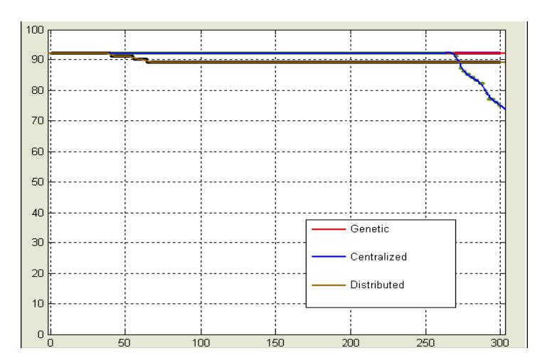
In the figure below, a comparison has been made among three methods, Evolutionary algorithm, Centralized algorithm (2004 strategy) and distributed algorithm (2007 strategy).
4.1.3. Ambulance Team Strategy in 2009
Our previous ambulance teams' main problem was the search for civilians; when they were found lately, the agents were under stress condition and as the result they couldn't show their real performance, so we have to improve our search method first of all.
For performing rescue task, each agent itself chooses a civilian (a local view choice) and in the mean time the center also assigns some tasks to the agent (global view choice) - and then each agent chooses between the possible and proper choices.
Because the evaluation parameters have changed so we really can't decide about our agent choosing strategy, so we need more analyzes before we can talk about.
4.2. Fire Brigade Team Strategy in 2009
Analyzing many logs from our previous strategies and other teams revealed that trivial (yet important) things had been ignored, so we are going to add them to our source code. This year we aim to look the Fire problem with a new approach and also to challenge violating some strategies that are assumed to be basis of fire extinguishing solution.
In previous years we stressed on choosing the best Fire Zones to extinguish them respectively; but this year we mostly zoom on our local strategies strategies used to extinguish and control fiery buildings of a fire zone-, because we are assured that with a perfect local strategy the agents will use less water; resulting into less time moving to refuges and filling their tanks, so we would be able to achieve much better results.
4.2.2 Global Approach
We are to add two new vital changes in our global Approach:
- In the preliminary cycles, Fire Brigades try to spread among Fire Zones (the nearest zone),and with a proper local strategy try to extinguish or control the fires till, they get familiar to the map and the city becomes more accessible; then the need to act cooperatively on a specific Fire Zone gets more vital.
- Second point that we insist on to observe is to stick to a Fire Zone till it is completely putout and never change our target Fire Zone even if after some time we recognize another Fire Zone is more important. As experience has shown if we stick to the fire zones that previously we discarded them we will get far better result overall.
4.2.3. Local Approach
Dividing each Fire Zone in two main parts (1st the Core – Buildings that have the most influence in fire propagation and the most energy of the Fire Zone-, 2nd the other Buildings that are not of that importance or are small enough) is one of our featured local strategies for this year.
Pre extinguishing the buildings is one of the best ways to control the fire, so we would use it widely in our local strategies.
It is obvious that, for extinguishing a fiery building heat deflects are needed. When a building is on fire and its temperature is increasing, providing this heat deflect is difficult and in many cases strong cooperation among a number of agents is needed. We aim to extinguish only new Fires and for other Fiery Buildings we cool them after they are burnt or their temperature is decreasing by itself (after they have hit their maximum point of heat) where providing the deflect is more easy and there is no need of strong cooperation between agents –cooperation among agents is costly and it wastes move and time, as the result we need more water to fill in the tanks which takes much time and so on. It goes without saying that we should avoid this vicious cycle-. We are determined to use this new approach even at the expense of losing a bit score in fires second evaluation parameter in the recently released score vector.
Our other consideration would be the fire Brigades positioning around the target Fire Zone, which could do us good through saving the time of numerous moves around the Fire Zone and helping us establishing cooperation using "say".
One of our most important Local Strategic changes is restricting the fires to their near most roads because statistically more than 85% of buildings can't transmit fire to the other side of road by themselves.
We would make use of other new major and minor Strategic changes (more than 100 small strategic bugs are detected), which bringing them in detail, is beyond the scope of this article.
4.2.4. Communication and cooperation
To establish communication and cooperation between agents as well as updating their world models we aim to minimize the use of message –and maybe not to use message in many maps- and use "say" instead. Because each fire Brigade spends much of its time in the refuge filling water that is a very good time to update its world model .This is superb because in maps with no Ambulance Center or Police Office we could use Fire Station instead to provide coordination among other team agents.
4.3. Police Force Team Strategy in 2009
We have discovered some bugs in our police force agents implementation such as "fastMove" function and some other errors in their search phase which we are going to correct them, but our main ideas fir police force agents are same as previous years based on noble results achieved by our police forces in comparison with our rivals.
5. Agent Coordination
Depending on the strategy each agent decides in a specific situation, the decision will specify whether to work centralized or distributed, however center agents think that their platoon agents are working centralized so they provide centralized information needed by platoon agents.
As the platoon have almost the same world model their decision about this matter will be coordinated sufficiently.
6. Messaging System
6.1 Management:
Management unit can be divided in three smaller parts:
- Central Management unit
- o Manages Relationship between all other parts of Message System
- Channel Management unit
- o Manages the allocation of channels in different communicating conditions ( no station – no communication – one center – etc)
- Storage Management unit
- o Chooses message storing place
6.2 Structure:
In this system, we used an XML protocol definition. All agents used file in order to define their message types, it also contains the length of their tokens, and the potential senders and target agent of each type of message. Also, facilities for automatic filling of some fields and tokens with respect to the world model of the sending agent are available.
6.3 Database:
In order to have a good management, our database has some priority bases:
Each box structure is a mixture of a hash map, a queue and a stack. This mixture provides our needs and also it is easy to check messages' duplication.
When a box is full we use a FIFO structure to delete excess messages and also we use FILO structure sending a message.
6.4 Collecting:
When a message is received or is made, it must be stored in a data bank and finally in a data box to be sent. After realizing communication conditions, this part is in charge of storing message in destination data bank.
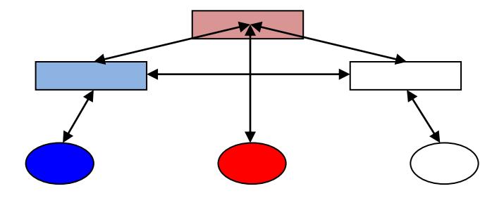
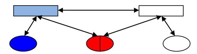
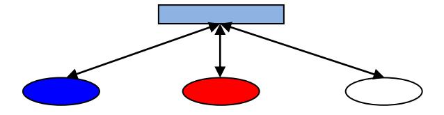
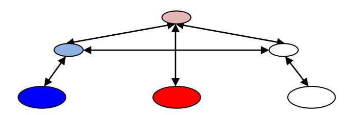
(In figures below: Rectangle: centers, Circle: platoon agent and small circle: captain)
Full Communication:
6.5 Distributing:
After collecting Messages, at the beginning of each cycle Messages will be sent. It is important how to distribute them, because we have restriction in sending and receiving messages, especially in one center communication.
6.6 Selection Method:
The messages which have the highest priority are chosen for being a package during each cycle.
6.7 Data Compression
We have used a method for data blocks with inconstant length. It uses more bytes for larger data blocks (ex. A number), and less byte for small data blocks.
6.8 Voice communication:
If we don't have radio communication, voice communication has a great importance. it has a less limitation than the radio communication, so it can be used in each and every condition.
7. Data Visualization and Tools
7.1. Extended Kernel Viewer
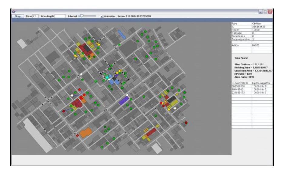
An improved version of official viewer of Rescue Simulation kernel was developed by S.O.S. members, and released on 2/22/2006, which has the following features;
(Figure 1)
- Shows all the attributes of the selected object in a list box.
- Shows state of an agent or civilian when selected in a list box.
- Shows the action of the selected agent with some details (e.g. for move action it shows the path of the move with the route IDs in a list)
- Some graphical information (e.g. the sense area of the selected agent, the notification of an action loss of an agent, coloring path of the selected agent and etc)
7.2. Extended Agent Viewer
An embedded viewer which has the ability to be enabled, the main purpose was to show the agent current world model, moreover it depicts all the strategy details of which the corresponding agent has decided. It also shows all the necessary details of every possible high level actions of every agent.
7.3. Logger
An organized logging system, which saves a complete history of each agent world model, their traverse in their decision tree, the detailed reasons which caused its transition between states and so on.
7.4. XML based messaging system
All the message parameters which specify homogenous/heterogeneous agents communication details can be manipulated offline in xml files, by updating the content of the files according to our needs.(Figure 2)
A part Message XML file.
8. Software Architecture
S.O.S. agents are implemented basically with an object oriented State-Based design pattern [4], which constructs each agent's decision model as a graph of states, each state nodes in the graph is likely to decide an action or may transit to another state, the transition to other states has some conditions which if they are satisfied by the information from world model the transition will be made, a priority is also considered for states which comes first in the transition section of each state.
The one very important feature of this state-based design, the code tries to maintain its last strategy (Route of Traversing State Graph) in each cycle as long as all the conditions of nodes within the route are still confirmed. Consequently this design will cause a desirable stability in the strategy of an agent. We use agile XP of various versions as our methodology of software engineering in developing agents.
9. References
- Ansari, M. et. al: S.O.S. Team Description Paper Proceeding of Robocup 2006.
- Azizpour, H. et. al: S.O.S. Team Description Paper Proceeding of Robocup 2007.
- Ghaffuri, M et. al: S.O.S. Team Description Paper Proceeding of Robocup 2008.
- Cormen, T., Leiserson, C., Rivest.: Introduction to Algorithms MIT Press, Cam bridge(2000).
- Horstmann, C: Object-Oriented Design and Patterns
References
- Ansari, M. et. al: S.O.S. Team Description Paper Proceeding of Robocup 2006.
- Azizpour, H. et. al: S.O.S. Team Description Paper Proceeding of Robocup 2007.
- Ghaffuri, M et. al: S.O.S. Team Description Paper Proceeding of Robocup 2008.
- Cormen, T., Leiserson, C., Rivest.: Introduction to Algorithms MIT Press, Cam bridge(2000).
- Horstmann, C: Object-Oriented Design and Patterns