RoboCupRescue 2010 - Rescue Simulation League Team Description Ri-one (Japan)
Yuki Matsuda, Hiroshi Ueno, Akifumi Komukai, Daiki Yoshihara, Shogo Suzuki, Kanako Watanabe, Gonkichiro Sumidai, Naoko Tanibata, Katsuari Kamei
Ritsumeikan University Japan
http://spice.ci.ritsumei.ac.jp/~robocup/public/index.php
Abstract As for the previous Ri-one team, Police force, Ambulance team and Fire brigade acted independently and respectively. This year, Task System has been added so that each agent can work more cooperative with other agents. And Layer has been improved to decide priority more efficiently. In addition, a concept of streets has been mounted to make roads a group.
1 Introduction
RoboCup Rescue Simulation (RCRS) is a multi-agent system to simulate a rescue in disasters. RCRS servers simulate multiple situations such as outbreaks of the disaster and damages of people and buildings. The earthquake destroys buildings and blockades roads. Furthermore, fire occurs and damages buildings. Agents must rescue civilians and terminate the spread of fire in this simulation. This paper describes firstly technique and algorithm. Secondly, this paper describes two big improvements of Task System and Network Model. The Ri-one team is constructed by utilizing YabAPI.
2 Agent Skills
This section describes the skills and behaviors of different agent types in the Ri-one team system.
2.1 Ambulance Team
Ambulance team (AT) searches for the civilians buried in buildings and helps them, then takes them to refuges. AT regards three things as important to rescue civilians efficiently.
- AT decides the order of priority to help.
- Until last year, AT considered the remainder of physical strength of each civilian. This year, AT also considers the position of fires. In the other word, AT rescues the civilian who is dying near the fire.
- AT considers the most suitable number of AT to rescue.
- AT finds the shortest route to the civilian.
- This helps avoiding wasteful time.
Synthesizing these things, our AT can rescue more civilians quickly.
2.2 Police Force
In last year, police force (PF) generated task by themselves. It caused the duplication of tasks to be done many times. In this year, PF is controlled by Task System which police office (PO) sents. By this Task System, the duplication of tasks never occurs. As a result, the work efficiency becomes higher than that of the last year system. The information of Task System is as follows:
- The blockade position to be removed by PF.
- The priority of the removal of the blockades.
Tasks are allotted to each PF by PO. In addition, PF has two tasks as follows:
- Task which must be done now.
- Task which should be done next.
PO changes Task System to perform a higher priority task next time. The priority of task is as follows:
- Places where the agents cannot move from the first place by blockades.
- Unreachable refuges' entrances.
- Blocked roads around fire.
- Make routes that agent rescue civilians.
PO can allot tasks to PF adequately by using Route Plan described in Section 2.6.
2.3 Fire Brigade
The main aim of fire brigade (FB) is to extinguish fire and prevent the burning area from spreading. To achieve the aim, FB must grasp the situation of the fire. When a lot of fires occur at the sometime, FB must decide which fire should be extinguished. Therefore, they must have a criterion for selecting the fires. FB uses FireGroup and BuildingGroup in the criterion. This year, ReachableArea has been added to the criterion to adapt to many blockades and extinguish fires more efficiently. Details about FireGroup, BuildingGroup and ReachableArea were discussed in last year's TDP[1].
FB uses the concept of Dynamic Task System to select the target fire. Using concept of Task System, FB can cooperate to extinguish targets. Details about the concept of Task System will be described in later section.
2.4 Change Action
Our team selects the proper line model of radio communication in various maps. Line model is determined by the number of center agents and platoon agents. Radio communication model uses the static communication together with a dynamic communication. For more detail on it refer to the section of Communication and Task.
2.5 Center Agent
Previously, the center agents were working as only a relay of communication. This year, the center agents have some new roles. When no-center situation, agents work without the center agent as last year's team.
2.5.1 Task
We have developed Task System for cooperative action of agents. The agents act based on task information. the tasks are generated by information as follows:
- Target of agents.
- Ways for the agents to complete the task.
- The number of needed agents.
- Priority of the task.
- Time when a task generated.
- List of agents in charge of the task.
Task System is composed of the following two systems.
Dynamic Task System: Center agent sends a list of tasks and each agent selects tasks in it. This system is used by FB and AT.
Static Task System: In Static Task System, the center agent selects a task and sends it to theselected agent directly. This system is used by PF.
This system is customized to an easy-to-use for each agent. As for the previous each agent acted based on an action prediction of other agents. However, in this year, works are assigned to the agents more certainly by introduction Task System. Therefore, the agents can act more accuracy and cooperative.
2.6 Route Plan
The agents make a Route Plan using Street described in section 3.2. Street frees the agents from the search of nodes and roads. Therefore, the agents are able to save calculation time for making Route Plan. The agents make a Route Plan by using different ways for a single destination and all the destinations, respectively.
In the former case, the agents check the shortest route to the destination considering blockades, then make the Route Plan by A* algorithm. The agents use this way to move for the civilians and burning buildings.
In the latter case, the agents must pass through all the destinations. Therefore, they make a Route Plan by A* algorithm and depth-first search. The process to make it is as follows:
- The agents calculate the costs between current place and each destination by A* algorithm.
- They calculate the costs between the destinations in the same way.
- Based on the costs, they make a Route Plan by depth-first search.
The agents use this way to move for searching the civilians. In addition, PF cleans blockades with this way.
3 World Model
This section describes the world model used by the Ri-one team.
3.1 Layer
The concept of Layer and District system of our last year's team has been succeeded to this year's team. Layer is composed of FireLayer, BlockadeLayer and BuriedLayer. For more details on Layer and District, refer to last year's TDP[1]. For this year's team, we improved FireLayer, by addition of an estimation of the fire disaster. Consequently, the agents are able to deal with the disasters well.
3.2 Street
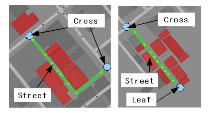
A route consists of roads and nodes. The agents must decide on their route by considering much information of roads and nodes. To solve this problem, we define Leaf and Cross. Leaf is the node connected to one road. Cross is the node connected to three or more roads. The agents construct Street between Cross and Cross or Leaf and Cross as shown in Figure 1.
The agents can get the route information easily by using Street. For example, the agents can judge not to go through the route even if they don't check roads and nodes of the route if Street contains one or more blockaded roads.
4 Communication
This section describes the communication model used by the Ri-one team.
4.1 Communication Model
Last year, we used two network models of the dynamic one and the static one. Our team analyzed the situation and selected a better network model. For more detail on Communication Model, refer to last year's TDP[1]. This year, we have developed new communication model that unifies the dynamic network model and the static network model.
The new communication model uses mainly dynamic network model. In the dynamic network model, the agents are divided into groups based on distance between each other. They communicate with other groups by using channel decided randomly. This model uses a network bandwidth efficiently.
In addition, the center agent in each group joins dynamic network model. Therefore, the center agent can work efficiently by using their capacity for communication.
4.2 Communication Stability
Our team can understand the activity situation of the center agent during the rescue simulation. When the center agent is working, both of the static network model and the dynamic network model are used. When the center agent is not working, the platoon agents communicate with other agents by using the communication model except the static network model. By this communication model, the agents communicate with each other rightly.
5 Tools
This section describes the tools developed by the Ri-one team for simulation and debugging.
5.1 3D Monitor
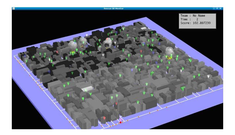
We made the tool "Rescue 3D Monitor" which could display information of RCRS in 3D. All members of Ri-one want a lot of people to be interested in RCRS by the development of this tool. Figure 2 shows a screen shot of "Rescue 3D Monitor windows".
The functions of Rescue 3D Monitor are as follows:
- Show 3D disaster space form over the sky.
- Change any angles of the bird's-eye view of map with a mouse.
- Playback the actions of agents, firing and smoking in 3D.
We want you to use this tool at many competitions. Last year, Rescue 3D Monitor was used in RoboCup Japan Open 2009.
5.2 Logger
Logger gives programmers a message on an appropriate level during their codings to reduce the burden of programmers in debugging the programs.
Summary of Logger: We add five levels of the debug message and the error message to display the information. Only a specific place in the window allows to display the message of the details. Logger outputs messages when we have done an exception in the latest edition directly.
LogLevel: LogLevel prevents Logger from displaying the messages whose level is lower than LogLevel.
5.3 Rescue Visualizer and Debug Client
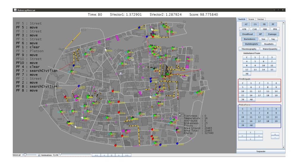
Rescue Visualizer and Debug Client are tools to debug visually. Debug Client receives the information of the agents and sends it to Rescue Visualizer. For more details on Rescue Visualizer and Debug Client, refer to our last year's TDP[1]. Figure 3 shows appearance of Rescue Visualizer.
We have improved Rescue Visualizer and Debug Client this year. Improved or added functions are as follows:
Display FB's Water Quantity
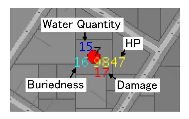
Old Rescue Visualizer can display a part of information about the agents. This information is HP, Damage and Buriedness. The latest Rescue Visualizer can display FB's water quantity. Figure 4 is a screen shot that displaying the agent's information.
New Function Panel
Old Rescue Visualizer had two different function panels. One is the control panel, the other is the information panel. The information panel displays the information of the field such as the number of agents, the ratio of living agents and the ratio of burnt buildings, etc. The latest Rescue Visualizer had the third function panel, the score panel. The score panel shows details of score based on the rule of RoboCup2009.
Thermograph Mode
Thermograph mode gives us the information of building's temperature visually. Figure 5 shows a screen shot of the map in Thermograph mode.
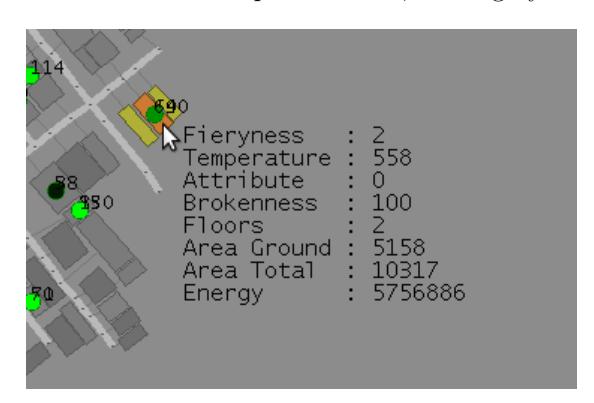
Building's Information
You can get building's information when you point the building in cursor. Information of you can get is as follows:
- Fieryness.
- Temperature.
- Building attribute.
- Brokenness.
- Number of floors.
- Building area of ground.
- Building area of total.
- Energy of building.
Figure 6 is a screen shot displaying the building's information.
Display Road's Information
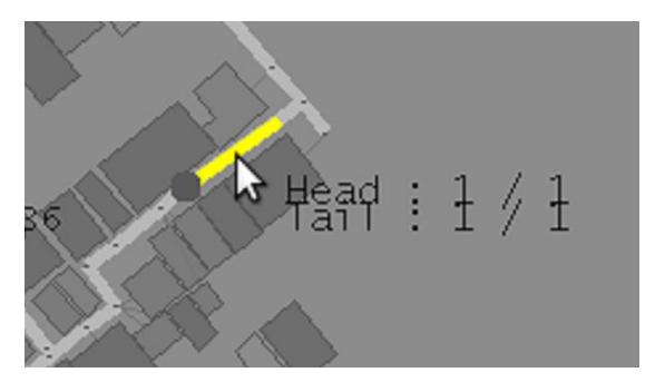
You can get road's information when you point the road in cursor. Information of you can get is as follows:
- Number of total lines to head.
- Number of total lines to tail.
- Number of passable lines to head.
- Number of passable lines to tail.
- Which side of road is head.
Figure 7 shows a screen shot displaying the road's information, where line is the pointed road, and a gray circle is a head side of road.
6 Acknowledgment
We are indebted to Hiroshi Aoki, Yuto Otsuki, Kazuhiro Shiraishi, Satoru Suzumoto, Kyohei Nishide, Masayuki Hasegawa, Yasuhiro Hiramoto, Yu Yamaguchi for their advices.
References
[1] Y. Otsuki, H. Aoki, K. Nishide, Y. Yamaguchi, Y. Matsuda, A. Komukai, H. Ueno and K. Kamei: RoboCupRescue 2009-Rescue Simulation League. Ri-one's Team Description (2009).