RoboCup 2011 – Rescue Simulation League Team Description Paper SBCe_Saviour
Eslam Nazemi, Mohammad Goodarzi, Reza Emami, Nazanin Calagar Darounkola, Seyed Ali Ahmadnejad
Department of Electrical and Computer Engineering Shahid Beheshti University, Tehran, Iran
Abstract This paper describes the main ideas and new methods implemented in SBCe_Saviour team in order to participate in RoboCup2011 competition. Recently, RoboCup Rescue Simulation server has been changed in a way that it becomes more realistic. Our new team has experience of participating in the competitions since 2006 and we already developed several algorithms in the environment. Thus, our target for 2011 competition is to handle new features added to server and tune our legacy algorithms to be efficient in new server. Agents' coordination and communication methods are our first concern for this year's competition. Afterwards, Path-Planning strategies using A* and tuning our decision making algorithms in order to be used in large multi-agent systems (with more than 200 agents) are our next priorities.
Introduction
RoboCup Rescue Simulation server 1.0 has several improvements in comparison to the old system. New definition on radio channels and communication system is added. Channels have bandwidths and level of reliability. These factors completely defy our old algorithm described in [1]. Moreover number of agents in scenarios is increased significantly and this also has negative effect on our old algorithm's performance. As communication methods and information sharing are very important in the whole team's performance, our first target for RoboCup2011 competition is to improve the agents' communication system. We had a full survey on this in [4] and we will briefly describe the concepts and algorithm in part 2.
Today, our rescue scenarios include more than 60 agents and we have new maps with more than 3000 areas. These changes reduce the performance of the teams significantly. Besides, new area-based traffic simulator adds more challenges in the system. We constructed new data structures on areas and implemented a fast areabased A* algorithm for our team. We will describe data structures and new algorithm in part 3. In part 4, we will have an overview on our decision making algorithms. There are some changes in the server and we also have some improvements with regards to these changes (e.g. centers may burn in the fire in new server.)
Agents Coordination and Communication System
Agents in RS are not able to percept the whole information exists in the environment in each cycle and moreover agents cannot share all of their information because of message sending constraints considered in RoboCup Rescue server. Thus, having an efficient decision making system to select the most important pieces of information to send with respect to different situation and also appointing the most efficient agents to get the information can lead to considerable improvement in agents' overall performance [2].
In new server, channels have two main specifications: Bandwidth and Noise Ratio. With these new changes we have lots of unpredictable scenarios. Our old algorithm was based on channels but it was almost static because the only parameter which was subject to change was number of centers and agents. In order to solve the agents coordination and communication problem in this case, we used a heuristic tokenbased method. First, we need to have survey on some concepts including Scale-Free Networks and Tokens and then propose our algorithm.
Agents' Underlying Network: Scale-Free Networks
Scale-free networks are structures in which small numbers of nodes have large number of neighbors and large numbers of nodes have small number of neighbors [6]. In this topology, the nodes with large number of neighbors are called hub and have duty to establishing the connection between other nodes. This network is shown to be very effective [5] in information sharing problems.
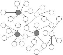
One of the most important features of scale-free networks is their scalability. New nodes can be easily added to the network while the whole structure is remaining the same and the performance of information sharing will be saved [6].
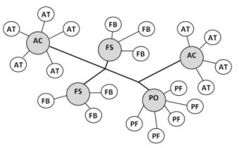
In RS centers are capable of getting information from several radio channels and broadcasting large amount of information. In contrast, individual agents are limited in this matter. There are two conceivable situations in RS: normal and centre-less scenarios. In the former, centers are our hubs in a scale-free network and individual agents communicate with their centre and in the latter, one or more agents will be selected among each type of agents and work as a hub. As the agents' ability to save and broadcast the information is less than the centers, the performance of the network will be reduced in centre-less scenarios. The structure is shown in figure 2.
Information Tokens
Tokens are packages consist of information about the environment which should be circulating between agents in the team. Tokens are generally in three types of Resource, Role and Information tokens. Our focus in RS is on information tokens which encapsulate the environmental information. We are presenting our information tokens in RS with regards to our previous research in [2]. List of tokens obtained from the proposed method in [2] are:
- Civilian Dead Token
- Civilian Average Token
- Buried Civilian/Agent Token
- Building Burned Token
- Road Blocked Token
- Civilian Critical Token
- Civilian Healthy Token
- Building Burning Token
- Building Semi-Burned Token
- Road Clear Token
Coordination Algorithm
Each individual agent will locally decide where to send its tokens. Our method is working based on tokens and their similarity. In this model, we consider a twodimensional matrix $P_a$ for each individual agent a. Columns define the neighbors of the agent and rows are tokens in the history of the agent $(H_a(t))$ . The values in the matrix are between 0 and 1 and define the importance of the token for each neighbor. For instance, if $P_a[\Delta_i, b] = 0.6$ it means that $\Delta_i$ 's importance for agent b is 0.6 from the view of the agent a. Thus, the best decision for agent a is to select the token and the neighbor with the maximum value in the $P_a$ matrix. The optimal policy is as follows:
$$\pi = \operatorname{argmax}_{x \in Action_a} P_a[\Delta, c], x = \operatorname{move}(\Delta, c)$$
The $P_a$ method is based on receive and store of the information from the environment during the agent life cycle. $P_a$ is just based on $H_a(t)$ . Agents do not know where to send tokens at first, but with receiving the information they will use an update model in order to first update their matrix and then send the token to the best acquaintance. We define the update function for $P_a[\Delta_j]$ according to $H_a$ as below:
$$\forall b \in n(a), \forall \Delta_i \in H_a, d = first(n(a), \Delta_i, path)$$
$$Update(P_a[\Delta_j, b], \Delta_i) = \begin{cases} P_a[\Delta_j, b] \times Rel(\Delta_i, \Delta_j) & \Delta_i \neq \Delta_j, b = d \ P_a[\Delta_j, b] & \Delta_i \neq \Delta_j, b \neq d \ P_a[\Delta_j, b] \times \varepsilon & \Delta_i = \Delta_j, b \in \Delta_j, path \cap n(a) \end{cases}$$
For deep explanation and the experimental results please refer to our work in [5].
Tokens' Similarity and Update Function
Similarities between tokens are calculated with regards to: distance between the location of tokens and tentative heuristic bias value. We have four distinct token categories including Civilian Tokens, Buried Tokens, Building Tokens and Road Tokens. Tokens in the same groups are 100% similar and the rest of similarities are as follows:
- Civilian ~ Building = 0.6 Civilian ~ Buried = 1 Civilian ~ Road = 0.5
- Building ~ Civilian = 0.6 Building ~ Buried = 1 Building ~ Road = 0.5
- Road ~ Civilian = 0.6 Road ~ Buried = 0.6 Road ~ Building = 0.6
The bias value is multiplied by the distance between the locations of the tokens and makes the final similarity between tokens. All values are obtained after several experiments in Rescue Simulation environment.
Area-Based Path-Planning and Region Management Engine
In new area-based traffic simulator all buildings and roads are areas that agents can make use of them in order to move in city. These areas are 2D shapes and their number is far greater than the roads number in old maps. Blockages are also 2D shapes which are placed in areas and may block the agents' path.
ComplexRoad and LogicalRoad Data Structures
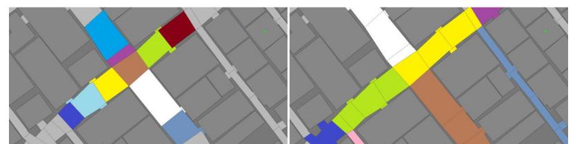
ComplexRoads are new entities we added to the rescuecore2 API and are consist of several Road objects. There are always plenty of small roads that connect other big roads in the junctions or connect roads to the buildings in the map. A ComplexRoad is collection of a Road and its small neighbor areas. This data structure helps our methods to become significantly fast. Table 1 shows number of Roads and ComplexRoads in different maps.
Table 1. Number of roads and complex roads in different maps
| Map | Number of Roads | Number of ComplexRoads |
|---|---|---|
| Kobe | 1515 | 801 |
| VC | 1954 | 838 |
| Berlin | 3385 | 2419 |
| Paris | 3025 | 2342 |
LogicalRoad is a data structure consists of several ComplexRoads. In many applications (e.g. Regioning the city) checking all areas or ComplexRoads is very timedemanding. In these cases we use LogicalRoads. Figure 3 show Areas, ComplexRoads and LogicalRoads in a part of Kobe map.
Path-Planning Engine (PPE) and Region Management Engine (RME)
PPE is a framework which agents use for finding a path in the city. The engine is using ComplexRoads and LogicalRoads data structures and use an A* path finding algorithm in order to decide the nearest route to agents' destinations. Each agent has its own instance of PPE and updates the status of blockades and banned roads while performing in the environment. PPE will use this data in order to define weights on roads, complexRoads and logicalRoads. Thus, agents won't be trapped behind a blockade if they have another path to their destination.
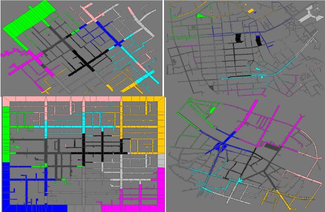
In SBCe_Saviour's abstract decision model, agents should start to search and find victims and gather information from the environment when their information is not sufficient for performing a task in the system. We use a RME to partition the whole city to definite number of regions. Agents have the duty of finding any victims and reporting the information related to their region to the whole team. RME uses an algorithm based on BFS to partition the map. Figure 5 show 10 regions created by the engine in different rescue new known maps.
Police Force Agents
The major task of police force agents is to connect the separated parts of the city caused by debris. This work should be done in the less possible time. Our previous strategies for police force agents are very useful and efficient [9]. However, with new major changes in RoboCup Rescue server and new scenarios with large number of agents, civilians, fire points and blockades the previous methods lost their performance. According to our researches in nature inspired task allocation methods, we believe that in a large, complex and stochastic system like Rescue Simulation, a decentralized and adaptive task allocation method should be used.
Decentralized Approach to Police Force Task Allocation
One solution to decentralized decision making is the models based on social insects' behavior [10] and response threshold theory [11]. In our method each individual agent has a set of roads that should be cleared. Dynamic and environmentdependent values called stimulus are assigned to each task. While the need of doing a specific task is more required, task's stimulus level increases consequently. We considered the number of clear requests received from the team mates as the task's stimulus value in our method. Moreover, each individual agent has a set of values called thresholds which indicates the minimum level of tendency to involve in respective task. Generally agents are more likely to engage in a task when the level of stimulus associated with that task exceeds task's related threshold.
Each agent a has a set $\theta_a = {\theta_{a,0}, \dots, \theta_{a,n}}$ which holds threshold values for each task = 0, ..., n. Each task j has a stimulus value $S_i$ , 0 < j < n, $S_i > 0$ . Probability T of involving in a task for each individual agent is obtained from equation (1):
$$T_{\theta_{a,j}}(S_j) = \frac{S_j^n}{S_j^n + (\theta_{a,j})^n}, n \ge 2$$
Where $T_{\theta_{a,j}}(S_j)$ is the probability of involving agent a in task j. Using above equation, if the level of stimulus is equal to threshold value; the probability of involving in the related task is ½.
We use variable threshold values method for our task allocation system. In this approach, threshold values can be dynamically evaluated according to system elapsed time and the current involved task [11]. As an example for this approach, if task i is performed by agent a, its threshold decreased by $\theta_L$ in each cycle and other tasks' threshold values are increased by $\theta_H$ .
$$\theta_{a,i} = \theta_{a,i} - \theta_L$$
$$\theta_{a,j} = \theta_{a,j} + \theta_H \quad for each \ 0 < j < n, j \neq i$$
$\theta_{a,i}$ : Threshold value of task i for agent a. n: Number of tasks for agent a.
Experimental results and obtained performance of our decision model for police force agents are fully presented in [3].
Fire Brigade Agents
The main ideas and list of effective parameters in fire brigades decision making algorithm are presented in our previous presentations [1, 8]. However, we found that agents' performance can improve by defining some new parameters such as Fire Zones and Fire Prediction.
Fire Zones and Fire Prediction
Fire zone is a set of adjacent buildings which are delimited by wide roads. The goal of using this concept is to use fire prediction idea to reduce fire propagation. In fact, this idea helps us to select the building with most priority by first selecting the target fire zone regarding to fire zone's material and total area of buildings inside it and then inside the selected fire zone. The most prior building is selected with the parameters including building's fieriness, building's area, adjacency to civilians' center, being a border building of fire zone and building's material type.
Fire Prediction method is used to prevent conduction of fire between adjacent fire zones. Conduction of fire among buildings inside a fire zone happens much faster in comparison to conduction between two fire zones. Therefore, it is very important to stop the fire in a zone and prevent the fire propagation to its neighbor zones. Also regarding the importance of message centers, the Fire Prediction helps fire brigades to extinguish the buildings around before the fire is conducted to a message center itself. In order to perform the fire prediction process, we first need to divide the city into a grid. Then the fire prediction will be able to give us the current and next temperature of each grid partition. The next temperature for each point of the city is obtained from equation (2):
MN'C*, O = N'C*, O + -NC*, O − N'C*, O. ∗ Q 2
where AverageTemp is the effect of neighbor cells' temperature and relevant building temperature and the parameter C is obtained from AIR_TO_AIR_COEFFICIENT and TIME_STEP_LENGTH.
Ambulance Team Agents
The implementation of our ambulance team is based on state machines and automata theory. In an ideal situation, the cyclic process of rescuing and transferring a victim to the refuge involves the following six states in Figure 6. It is obvious that surveying these steps is dependent on the circumstances that can occur in every step.
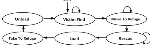
The first step in the rescuing process is choosing a victim. Considering the time limitation and the cost for rescuing, victim selection must be done in a way to result in the survival of the maximum number of victims. SBCe's strategy that is being used now is as follows: The victims are inserted in lists depending on the number of the ambulances which they need to be rescued before die. Then they are assigned priority values by the parameters containing estimated hp, damage, type of victim, buriedness, estimated time to death and victim's position (for calculating distance of the victim to the refuge and the ambulance agents).
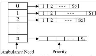
Each ambulance agent selects a victim as a target in the list which has the least ambulance need and the most priority value. To prevent interference of other ambulance agents, every ambulance agent considers the target of other ambulances that it has informed by communicating with them.
References
- SBCe_Saviour Team Description Paper for RoboCup Rescue Simulation League, Shahid Beheshti University, Iran (2008)
- Goodarzi, M., Radmand, A., Nazemi, E.: An Optimized Solution for Multi-Agent Coordination Using Integrated GA-Fuzzy Approach in Rescue Simulation Environment, 2nd International Workshop on Agent Technology for Disaster Management (ATDM) during the 12th International Conference on Principles in Multi-Agent Systems (PRIMA), Nagoya, Japan (2009)
- Goodarzi, M., Sedighi Gilani, M.H, Emami, R., Nazemi, E.: Response Thresholds as a Model for Adaptive Task Allocation in Rescue Simulation Environment, International Conference on Automation, Robotics and Control Systems (ARCS-10, FL, USA, (2010)
- Calagar Darounkola, N., Goodarzi, M., Nazemi, E., Ahmadnejad, S.A.: Large-Scale Information Sharing in Rescue Simulation Environment, The 1st Joint Conference of Robotics & AI – 3rd RoboCup IranOpen International Symposium, RIOS11, (2011)
- Glinton, R., Sycara, K., Scerri, P.: Agent Organized Networks Redux, In Proc. Of AAAI'08, 2008
- Xu, Y., Lewis, M., Sycara, K., Scerri, P.: Information Sharing in Large Scale Teams, In AAMAS'04 Workshop on Challenges in Coordination of Large Scale Multi Agent Systems, (2004)
- Barabasi, A., Bonabeau, E.: Scale Free Networks, Scientific American 60-69, (2003)
- SBCe_Saviour Team Description Paper for RoboCup Rescue Simulation League, Shahid Beheshti University, Iran (2009)
- Radmand, A., Nazemi, E., Goodarzi, M.: Integrated Genetic Algorithmic and Fuzzy Logic Approach for Decision Making of Police Force Agents in Rescue Simulation Environment, Proceeding of RoboCup2009 Symposium, (2009)
- Price, R., Tino, P.: Evaluation of Adaptive Nature Inspired Task Allocation Against Alternate Decentralized Multiagent Strategies, Parallel Problem Solving from Nature-PPSN VIII, (eds) X. Yao et al. pp. 982-990, Lecture Notes in Computer Science, Springer-Verlag, (2004)
- Bonabeau, E., Dorigo, M., Theraulaz, G.: Swarm Intelligence: From Natural to Artificial Systems, Oxford University press, edition 1,(1999)