Amsterdam Oxford Joint Rescue Forces Team Description Paper Virtual Robot competition Rescue Simulation League RoboCup 2008
Arnoud Visser, Tijn Schmits, Steven Roebert, Julian de Hoog
Universiteit van Amsterdam, 1098 SJ Amsterdam, the Netherlands; Oxford University Computing Laboratory, Parks Road, Oxford OX1 3QD, UK
http://student.science.uva.nl/~tschmits/USARSimOmniCam/
Abstract With the progress made in active exploration, the robots of the Joint Rescue Forces are capable of making deliberative decisions about the frontiers to be explored. The robots select the frontiers having maximum information gain, taking into account potential communication limitations. The robots incorporate the positions of their team mates into their decisions, to optimize the gain for the team as a whole. Active exploration is based on a shared occupancy map, which is generated online. The images of the omnidirectional camera can be used to automatically detect victims and to add additional information to the map.
Introduction
The RoboCup Rescue competitions provide benchmarks for evaluating robot platforms' usability in disaster mitigation. Research groups should demonstrate their ability to deploy a team of robots that explore a devastated area and locate victims. The Virtual Robots competition, part of the Rescue Simulation League, is a platform to experiment with multi-robot algorithms for robot systems with advanced sensory and mobility capabilities. The developed algorithms should be directly portable to fieldable systems, as demonstrated by several of the participating teams [1].
This year, shared interest in the application of machine learning techniques to multi-robot settings has led to a joint effort between the laboratories of Oxford and Amsterdam.
1 Team Members
UsarCommander was originally developed by Bayu Slamet and all other contributions have been built into his framework.
The following contributions have been made by current and past team members:
Arnoud Visser : supervision [1], exploration & navigation algorithms [2], communication protocol [3]
Bayu Slamet : GUI, real time visualization [4], several scan matching algorithms, manifold-SLAM [5, 6], communication protocol [3], exploration behaviors [2]
Max Pfingsthorn : off-line rendering, several scan matching algorithms, manifold-SLAM, navigation behaviors [5, 6]
Tijn Schmits : image processing, victim detection [4], sensor development [7], GUI, communication protocol
Xingrui-Ji et al. : occupancy grid map interpretation, beyond frontier exploration [8]
Aksel Ethembabaoglu : image processing, active target tracking [9]
Steven Roebert : map attribution, omnidirectonial camera usage
Julian de Hoog : multi-robot exploration algorithms, communication roles
2 Scan Matching
The possibilities for active exploration are heavily dependent on a correct estimation of a map of the environment. Many advanced techniques that aim to detect and correct error accumulation have been put forward by SLAM researchers. Although these SLAM techniques have proven very effective in achieving their objective, they are usually only effective once errors have already accumulated. With a robust scan matching algorithm the localization error is minimal, and the effort to detect and correct errors can be reduced to a minimum (see e.g. [10]).
Slamet and Pfingsthorn [5] performed an extensive survey of the performance of three scan matching algorithms in different environments. The survey demonstrated strong performance indoors, but less reliable results outdoors. Outdoor environments can contain large free spaces, where only sparsely obstacles are detected. Consequently, the scan matching algorithms were extensively tested in 2007 for outdoor environments and it was demonstrated that the robustness of the scan matching algorithms could be improved by matching against accumulated scans. With a storage technique like quad trees this accumulation can be done without losing the accuracy of the measurements.
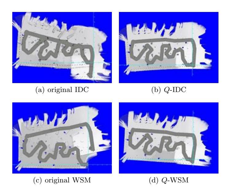
One of the experiments was performed in the outdoor area of the 2006 Virtual Robot competition, which we call 'The Park'. The experiment involved use of two implementations of the ICP algorithm [11]; IDC [12] and WSM [13]. The point-correlation procedures of the original implementations were replaced with a nearest neighbor-search in a quad tree. No additional modifications were made to the internal workings of these scan matchers, so we refer the interested reader to prior research [6, 5] and the original papers for further details. The experiments investigated the improvements that can be gained from using quad trees for both algorithms. The visualizations were created with the standard occupancy rendering techniques from [6]. All presented results are strictly based on scan matching.
For the experiment, an area of approximately 80 by 40 meters was used, with the robot starting in the bottom-right corner and traversing the park in a clockwise direction. The robot's path is shaded with gray for clarity and should describe a single closed loop from tip to tail. Both original scan matchers accumulate significant error; IDC 'overshoots' the end of the loop and WSM leaves a gap of several meters. Using the accumulated scans in the q-tree both IDC and WSM close the loop implicitly. Over the whole dataset the average correlation distance reduces from 9.83 mm to 4.83 mm for IDC and from 10.20 mm to 5.62 mm for WSM.
3 Localization and Mapping
The mapping algorithm of the Joint Rescue Forces is based on the manifold approach [10]. Globally, the manifold relies on a graph structure that grows with the amount of explored area. Nodes are added to the graph to represent local properties of newly explored areas. Links represent navigable paths from one node to the next.
The mapping algorithm is not dependent on information about the movement of the robot for the creation of links. In practice the displacement as reported by the inertial navigation sensor serves as an initial estimate for scan matching. Outdoors, the measurements of the GPS sensor are used. Thereafter, displacement is estimated by comparing the current laser scan with laser scans recorded shortly before, stored in nearby nodes of the graph. As soon as the displacement becomes so large that the confidence in the match between the current scan and the previous scan drops, a new node is created to store the scan and a new link is created that corresponds to the displacement. A new part of the map is learned.
As long as the confidence is high enough, the information on the map is sufficient and no further learning is necessary. The map is just used to get an accurate estimate of the current location. The localization algorithm maintains a single hypothesis about where the robot currently is and does an iterative search around that location when new measurement data arrives. For each point the correspondence between the current measurement data and the previous measurement data is calculated. The point with the best correspondence is selected as the center of a new iterative search, until the search converges. Important here is the measure for the correspondence. For the Joint Rescue Forces, several scan matching algorithms are available (as introduced in the previous section) which can be used as correspondence measure.
The graph structure means that it is possible to maintain multiple disconnected maps. In the context of SLAM for multiple robots, this makes it possible to communicate the graphs and to have one disconnected map for each robot. Additionally, it is possible to start a new disconnected map when a robot loses track of its location, for example after falling down stairs.
The graph structure of the manifold can be easily converted into occupancy grids with standard rendering techniques, as demonstrated in Fig. 1 and [6].
4 Multi-Robot Exploration
The approach of the UvA Rescue Team in previous years [14, 4] was to passively acquire the information to be stored in the map while the robot or operator was wandering around pursuing other objectives, like finding victims. This year however the focus will be on active exploration: to explicitly plan the next exploration action which will increase the knowledge about the world the most. In this paradigm victim finding becomes the side-effect of efficient exploration.
A key aspect of this year's approach is that the information gain for areas of the environment not yet visited by the robot can be estimated with longrange laser range measurements. It is possible to generate two occupancy grids simultaneously [8]: one based on the maximum sensing range rmax of the range sensing device and another one based on a more conservative safety distance rsafe. Typical values for rmax and rsafe are 20 meters and 3 meters respectively.
The result is that the safe region determined by rsafe is a subset of the open area. Frontiers can then be extracted on the boundaries of the safe region where the robot can enter free space, and the area beyond each frontier (i.e. its associated information gain) can be estimated directly from the current map by calculating the amount of free space detected beyond it. For each frontier it is also straightforward to calculate how hard it is to reach (i.e. its associated movement cost) using a path planner.
Knowing both (i) the information gain and (ii) the movement cost for each frontier allows for active exploration. As discussed in [2], active exploration of the robots can be easily tuned by adjusting the balance between these two values. Shifting the balance in favor of information gain has the effect that robots explore mainly the corridors, while shifting the balance towards movement costs has the effect that the robots enter the rooms along the corridors.
An additional increasingly important consideration in multi-robot exploration is communication. Knowledge attained by the robots is only useful if it reaches the ComStation, but in many environments significant areas will be out of direct communication range. The extent of this range is difficult to predict, because it depends on the number and nature of obstacles in the line between the robot and the ComStation.
In our approach [3], typical signal levels in the environment are learned during exploration, to facilitate a more reliable prediction of communication success. The predicted signal levels are then incorporated into the estimation of the information gain: the more likely a robot will be able to communicate its knowledge from a certain area, the more interested it will be in exploring this area.
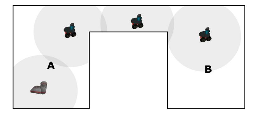
At the same time, however, there will inevitably be areas in the environment that are out of range but should still be explored. Knowledge gained about these areas by a robot may either be physically carried back to the ComStation, or communicated multi-hop to one or more robots acting as relays between the exploration area and the ComStation (see Fig. 2). The latter approach is likely to be more efficient in most scenarios, and will be implemented by dynamically assigning specific roles (such as explorer or relay) to robots during the ongoing exploration effort.
For the 2008 competition, extensive use will also be made of a-priori maps. The information gain can be better estimated with the difficult mobility areas indicated on the a-priori map. The prediction of communication success can be initiated based on the estimate of communication difficulty. The movement costs can be better estimated with level of difficulty of mobility.
5 Victim detection
Camera images can be used to automatically detect victims, independent from the Victim sensor provided by USARsim, as indicated in [4]. This independent information can be used to increase the robustness of the detection. This year the OmniCam sensor is introduced in USARsim [7]. An omnidirectional catadioptric camera has some great advantages over conventional cameras, one of them being the fact that visual landmarks (such as victims) remain in the field of view much longer than with a conventional camera. This characteristic will be exploited during the competition.
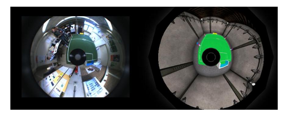
The Unreal Engine only allows a limited number of flat mirrors. To create an omnidirectional catadioptric camera with a parabolic mirror several security cameras are placed at the Effective Viewpoint inside the mirror, and their 2D images are displayed with UV-mapping on the parabolic 3D-surface in front of them. A normal UsarSim camera collects the world as displayed on the parabolic 3D-surface. As can been seen in Fig. 3, the result is very realistic.
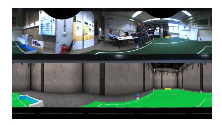
Omnidirectional camera pictures can be transformed to a cylindrical view according to the following equations describing the relation between cylindrical ucyl, vcyl-coordinates and omnidirectional xomni, yomni-coordinates [15].
$$x_{omni} = \left(r_{omni} \cdot \frac{x_{cyl}}{X_{cyl}}\right) \cos\left(2\pi \cdot \frac{y_{cyl}}{Y_{cyl}}\right)$$
$$y_{omni} = \left(r_{omni} \cdot \frac{x_{cyl}}{X_{cyl}}\right) \sin\left(2\pi \cdot \frac{y_{cyl}}{Y_{cyl}}\right)$$
In this equation the variable romni defines the maximum radius of the omnidirectional image in pixels, while Xcyl and Ycyl describe the width and height of the cylindrical image respectively. The result is shown in Figure 4.
Equivalently, the omnidirectional pictures can be transformed to a Birds-Eye view. The correspondence between a pixel in the omnidirectional image pomni = (xomni, yomni) and a pixel in the Birds-Eye view image pbe = (xbe, ybe) is defined by the following equations
$$\theta = \arccos \frac{z}{\sqrt{x_{be}^2 + y_{be}^2 + z^2}}, \quad \phi = \arctan \frac{y_{be}}{x_{be}}$$
$$\rho = \frac{h}{1 + \cos \theta}$$
$$x_{omni} = \rho \sin \theta \cos \phi, \quad y_{omni} = \rho \sin \theta \sin \phi$$
where h is the radius of the circle describing the 90 degree incidence angle on the omnidirectional camera effective viewpoint. The variable z is defined by the distance between the effective viewpoint and the projection plane in pixels [16].
6 Conclusion
This paper summarizes improvements in the control software of the UvA Rescue Team since RoboCup 2007 in Atlanta, where the semi-final was reached. This progress was demonstrated at the German Open 2008, where the final was reached. At RoboCup 2008 in Suzhou, the focus of the Joint Rescue Forces will be on active exploration of frontiers and the integration of the omnidirectional information into the user interface.
References
- Balakirsky, S., et al.: Towards heterogeneous robot teams for disaster mitigation: Results and performance metrics from robocup rescue. Journal of Field Robotics 24 (2007) 943–967
- Visser, A., Slamet, B.A.: Balancing the Information Gain Against the Movement Cost for Multi-robot Frontier Exploration. In: European Robotics Symposium 2008. Springer Tracts in Advanced Robotics, Springer-Verlag (2008) 43–52
- Visser, A., Slamet, B.A.: Including communication success in the estimation of information gain for multi-robot exploration. In: International Workshop on Wireless Multihop Communications in Networked Robotics. (2008)
- Visser, A., et al.: Design decisions of the UvA Rescue 2007 Team on the Challenges of the Virtual Robot competition. In: Proc. 4th International Workshop on Synthetic Simulation and Robotics to Mitigate Earthquake Disaster. (2007) 20–26
- Slamet, B., Pfingsthorn, M.: ManifoldSLAM: a Multi-Agent Simultaneous Localization and Mapping System for the RoboCup Rescue Virtual Robots Competition. Master's thesis, Universiteit van Amsterdam (2006)
- Pfingsthorn, M., Slamet, B., Visser, A.: A Scalable Hybrid Multi-Robot SLAM method for Highly Detailed Maps. In: Proceedings of the 11th RoboCup International Symposium. (2007)
- Schmits, T., Visser, A.: An Omnidirectional Camera Simulation for the USARSim World. In: Proceedings of the 12th RoboCup International Symposium. (2008)
- Visser, A., et al.: Beyond frontier exploration. In: Proceedings of the 11th RoboCup International Symposium. (2007)
- Ethembabaoglu, A.: Active target tracking using a mobile robot in the USARSim. Bachelor's thesis, Universiteit van Amsterdam (2007)
- Howard, A., Sukhatme, G.S., Matarić, M.J.: Multi-robot mapping using manifold representations. Proceedings of the IEEE 94 (2006) 1360–1369
- Rusinkiewicz, S., Levoy, M.: Efficient variants of the ICP algorithm. In: Third International Conference on 3D Digital Imaging and Modeling (3DIM). (2001)
- Lu, F., Milios, E.: Robot Pose Estimation in Unknown Environments by Matching 2D Range Scans. Journal of Intelligent and Robotic Systems 18 (1997) 249–275
- Pfister, S.T., et al.: A Weighted Range Sensor Matching Algorithm for Mobile Robot Displacement Estimation. IEEE Transactions on Robotics (2008) (in revision).
- Pfingsthorn, M., et al.: UvA Rescue Team 2006; RoboCup Rescue Simulation League. In: Proceedings CD of the 10th RoboCup International Symposium. (2006)
- Grassi Jr., V., Okamoto Jr., J.: Development of an omnidirectional vision system. Journal of the Brazilian Society of Mechanical Sciences and Engineering 28 (2006) 58–68
- Nayar, S.K.: Omnidirectional vision. In Shirai, Y., Hirose, S., eds.: Proc. of Eighth International Symposium on Robotics Research ISRR'97, Springer-Verlag (1998)