Amsterdam Oxford Joint Rescue Forces Team Description Paper Virtual Robot competition Rescue Simulation League RoboCup 2010 and Iran Open
Arnoud Visser, Quang Nguyen, Bas Terwijn, Moos Hueting, Robrecht Jurriaans, Martijn van der Veen, Okke Formsma, Nick Dijkshoorn, Sander van Noort, Radoslaw Sobolewski, Helen Flynn, Magda Jankowska, Swaroop Rath, Julian de Hoog
Universiteit van Amsterdam, Science Park 107, 1098 XG Amsterdam, NL; Oxford University Computing Laboratory, Parks Road, Oxford OX1 3QD, UK
http://www.jointrescueforces.eu
Abstract With the progress made in active exploration, the robots of the Joint Rescue Forces are capable of making deliberative decisions about the distribution of exploration locations over the team. Experiments have been done which include information exchange between team-members at rendez-vous points. Last year progress has been made with robots with advanced mobility, such as the Kenaf and the Air-Robot. Currently our navigation algorithms are extended to be able to autonomously explore with the AirRobots. Robots equipped with both camera and laser-range scanners can learn a visual classifier of free space, which could be used by robots without laser-range scanners to navigate through the environment. Part of our algorithms have been validated on the Nomad Super Scout II robot available in our laboratory.
Introduction
The RoboCup Rescue competitions provide benchmarks for evaluating robot platforms' usability in disaster mitigation. Research groups should demonstrate their ability to deploy a team of robots that explore a devastated area and locate victims. The Virtual Robots competition, part of the Rescue Simulation League, is a platform to experiment with multi-robot algorithms for robot systems with advanced sensory and mobility capabilities. With our participation in last year's Interleague Challenge we demonstrated that our algorithms are directly portable to fieldable systems[1].
The shared interest in the application of machine learning techniques to multi-robot settings [2] has led to a joint effort between the laboratories of Oxford and Amsterdam.
1 Team Members
UsarCommander was originally developed by Bayu Slamet and all other contributions have been built into his framework. Many other team members [3–6] have contributed to perception and control algorithms inside this framework.
The following contributions have been made this year:
Arnoud Visser : coordination [7], collaboration [8], exploration [9, 10], omnicam perception [11, 12], traversability maps [13], mapping evaluation [14–16], scan matching [17]
Quang Nguyen : navigation based on image interpretation [11]
Bas Terwijn : software performance analysis, UT3 development
Moos Hueting, Robrecht Jurriaans and Martijn van der Veen : navigation with AirRobot
Okke Formsma, Nick Dijkshoorn and Sander van Noort : smoke and fire simulation [18]
Radoslaw Sobolewski : automated robot navigation in rough terrain [19]
Helen Flynn : object recognition with weak classifiers [20]
Magda Jankowska : hough transform based map stitching [21]
Swaroop Rath : 3D mapping
Julian de Hoog : multi-robot exploration, communication roles [9, 10]
2 Scan Matching
The possibilities for active exploration are heavily dependent on a correct estimation of a map of the environment. Many advanced techniques that aim to detect and correct error accumulation have been put forward by SLAM researchers. Although these SLAM techniques have proven very effective in achieving their objective, they are usually only effective once errors have already accumulated. With a robust scan matching algorithm the localization error is minimal, and the effort to detect and correct errors can be reduced to a minimum. Several scan matching algorithms are available in our code, but during the competition the WSM algorithm [22] will be used, which has been efficiently implemented with Quadtrees [17].
3 Localization and Mapping
The mapping algorithm of the Joint Rescue Forces is based on the manifold approach [23]. Globally, the manifold relies on a graph structure that grows with the amount of explored area. Nodes are added to the graph to represent local properties of newly explored areas. Links represent navigable paths from one node to the next.
The graph structure means that it is possible to maintain multiple disconnected maps. In the context of SLAM for multiple robots, this makes it possible to communicate the graphs and to have one disconnected map for each robot. The graph structure of the manifold can be easily converted into occupancy grids with standard rendering techniques.
4 OmniCam rangescanner
Camera images can be used for teleoperation and to detect victims. Camera images can also be used as independent information to detect free space. Range scanners, which are typically used as primary means to detect free space, are active sensors which have a limited range and a limited field of view. Additionally, active sensors are relatively heavy and consume considerable amounts of energy, which makes them less attractive for small mobile robots. In contrast, the limit of a visual sensor range can lie as far as the horizon and omnidirectional vision methods can provide a 360◦ view of the environment. A method to identify free space based on visual sensor data could well expand the environment observation quality of a rescue robot.
Previous year, a visual free space classifier was trained using a laser-range scanner as reference [24]. This year, the classifier is used for navigation purposes. The images from an omnicam [12] are interpreted along polar-scanlines, to create range-estimates to obstacles. Those range-estimates can be further interpreted by scan-matching algorithms developed for laser-scanners, allowing simultaneous localization and mapping.
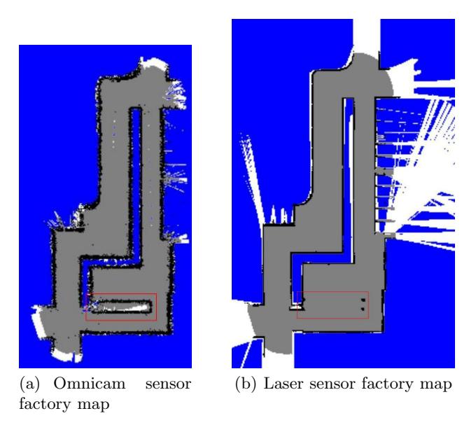
Figure 1(a) and 1(b) shows the results of building a map of the factory environment using an omnicam sensor and a laser sensor when ground truth is available as localization. Because of the accuracy of the laser measurements (less than a centimeter) the map 1(b) can serve as an indication for what the ground truth map should look like. The omnicam map does not differ that much from the laser created map. The black dots and lines on both maps represents detected obstacles, the gray color represents the safe space while the white color represents the free space detect by the rangefinder. Both gray and white indicates areas free of obstacles, but grey indicates areas that are well explored, while white indicates areas that could be further explored. The main difference is the thickness of the walls. The omnicam map is not as razorsharp as the map generated with the laser scanner. Yet, for navigation purposes this is not a disadvantage. A less obvious difference between both maps is visible at the bottom of the map, indicated with a red rectangle. The omnicam map has found a obstacle at that location while on the laser map only four small dots are visible. The omnicam map is correct at this situation, there is indeed a big obstacle present on this location; a cabinet. The laser scanner looked right through the cabinet, because no shelf was present at measurement height of the sensor.
5 Map Stitching
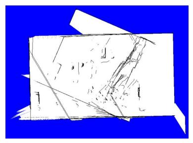
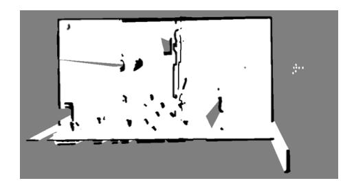
A common problem in robotic mapping occurs when a robot loses its orientation, for example after bumping into an obstacle. This can lead to multiple overlays on the map of the same obstacle, e.g. one wall may be represented by three different lines. The scan-matching method outlined above and developed in [25] has proven to be quite robust to such errors. However, it relies on subsequent scans being fairly close together. When a robot is traversing rough terrain it can be difficult to match subsequent scans as the laser range scanner is constantly tilting in different directions. To solve this problem we propose Hough-transform based map stitching [21].
In Map Stitching, two maps of the same environment, having some degree of overlap, are meant to be stitched together to form a single, unified map. Many algorithms exist for this purpose, but we have chosen to examine Hough-transform based map stitching [26]: this method is good at matching lines (common in rescue environments due to walls), is robust to noise, can be used online, and returns the translation and rotation between the two maps, which is useful for localisation.
The idea is as follows: when moving in flat terrain, use scan-matching as in previous years for precise mapping. Once bumpy, uneven terrain is encountered, turn the mapping off. After this difficult terrain has been surpassed (or a flat patch is reached), turn the scan matching back on to create a new map. If there is enough data and sufficient overlap, hough-based map stitching can be used to merge both maps and to relocalise the robot. An example is presented in Fig. 2.

6 Multi-Robot Exploration and Communication
In our previous work, an exploration approach was demonstrated which made a selection between a small number of frontiers, based on the information gain available beyond those frontiers [27]. Each robot may calculate the balance between movement costs and information gain for itself and for each of its teammates. Consequently an optimal robot-frontier assignment can be determined in which robots assign themselves to frontiers, and no frontier is explored by more than one robot. The result is efficient, fully autonomous multi-robot exploration.
Recently this approach has been extended into a "Role-based Exploration", which takes into account communication limitations [9]. In this exploration strategy robots assume the role of either explorers or relays. Explorers explore the farthest reaches of the environment, while relays periodically rendezvous with explorers and return new information to the ComStation. The result is a complete exploration of communication-limited environments in which information is efficiently returned to a central command centre.
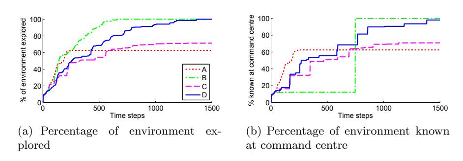
To evaluate this method, four different approaches were compared in a variety of environments:
- A. Frontier-based, no exploration beyond the team's communication range limits.
- B. Frontier-based, exploration beyond the communication range limits, and robots return when there are no more frontiers left to explore, i.e. when the exploration effort is completed.
- C. Frontier-based, exploration beyond the communication range limits and regular periodic return by each robot to the command centre.
- D. Role-based exploration beyond communication range limits, based on explorers and relays.
Depending on the performance measure, each of the approaches has its benefits. However, the role-based approach presents a good trade-off when both full exploration of the environment and regular updating of information at the command centre are required, as is the case for most rescue situations (see Figure 3).
A more recent study [10] indicated that choosing optimal rendez-vous points can improve the efficiency of the exploration with another 10%.
7 Autonomous navigation with AirRobot
To use the AirRobot for autonomous indoor exploration it is necessary to implement a motion which ensures that the AirRobot is capable of navigating hallways without bumping into obstacles. To allow autonomous exploration we equipped the AirRobot with 6 sonar-sensors with a range of approximately 5 meters. The sensors are set up with 4 sensors on the outer ring of the AirRobot to maximize the visibility in front of the AirRobot and the other 2 sensors pointing up and down to check the distance to the floor and ceiling.
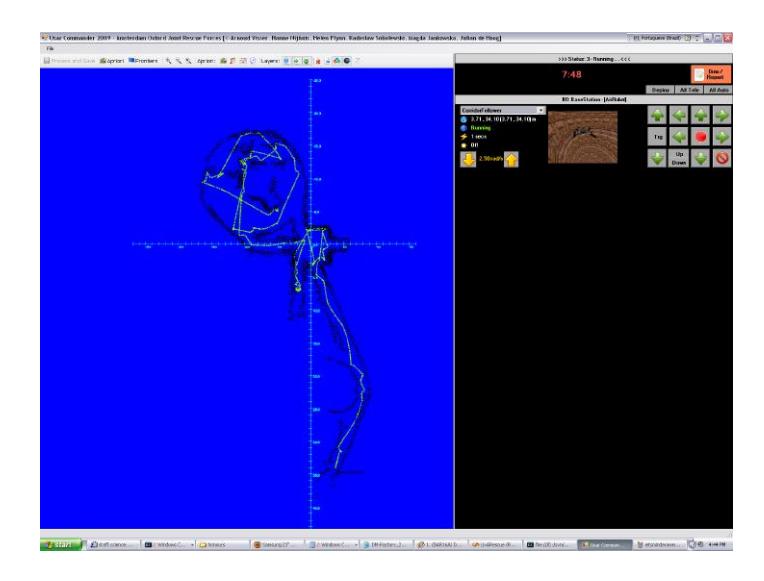
Flying using only the six range measurements received from these sensors is difficult since they do not allow a clear perception of the surroundings. The method we have decided on when flying indoors is based upon finite state automata, each state describing a navigational situation which the AirRobot might encounter. The combination of rules implemented in the automata give the AirRobot a tendency to position in front of hallways and then following the hallways until new rooms are found. When in an open space the AirRobot flies straight on until a new wall has been found which it will then follow. Communication with the user is achieved by drawing a map of the values returned by the sonars of the AirRobot. Currently only the 4 horizontal sonars are used for this sonar map (See Fig. 4). Including the down pointing sensor could lead to a height map. This would be the next step in achieving a more accurate representation of the environment.
What this algorithm achieves is that the AirRobot is capable of filling its battery life with exploration. The next step is to implement a function that extend this wandering behavior to a more goal oriented behavior capable to navigate between 2 points. This goal oriented behavior can in turn be used to navigate to the nearest encountered gateway. When these steps have been taken it is possible to deploy the AirRobot indoors for autonomous navigation using nothing more than the 6 sonar sensors. Before more stable and complex behaviors should be written, the current finite state automata implementation should be rewritten to graph-like system. This would create a solid base for navigational algorithms on the ground and in the air.
8 Rough Terrain Navigation
In spite of proposals for rough terrain mapping, such as map stitching (above), rough terrain continues to be a significant problem for robotics in general. In rescue robotics, a robot traversing slanting, bumpy, or obstacle filled terrain is typically controlled by a human operator, and requires this operator's full concentration. Since there are so many other tasks requiring human attention (looking for victims in camera feedback, noting environmental features of interest, monitoring the rescue effort as a whole), it would be useful to offload the rough terrain navigation to the robot, i.e. to make it autonomous.
We have experimented with a variety of control techniques for autonomous rough terrain navigation [19]. To gather training data, we ran a Kenaf robot over various types of obstacles in USARSim, with slightly random behaviour, several tens of thousands of runs. Subsequently this data was used to train a variety of machine learning techniques to develop automated control mechanisms, including artificial neural networks, neuro-fuzzy systems, and evolutionary neural networks. Over a variety of tests, it turned out that the evolutionary neural network approach performed best (including outperforming humans on the same task).
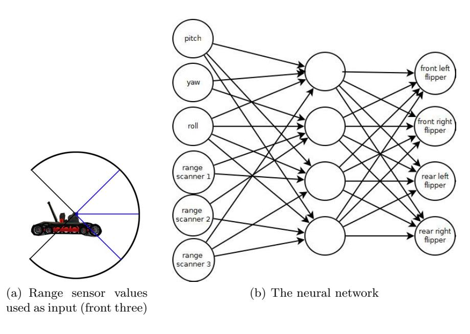
As input to our neural network we used the Kenaf robot's pitch, yaw and roll, along with three measurements from a vertically mounted Hokuyo range sensor (to detect the height/drop of obstacle ahead). These values were fed through a hidden layer, and the outputs returned movement up/down for each of the Kenaf robot's four flippers (see Figure 5). We hope to integrate this automated motion control into our control software in terms of waypoint navigation.
9 Object Recognition
The primary goal of rescue robotics is to recognise and find victims in the disaster area. A secondary goal is to map the environment, including landmarks of interest, so that human responders may find their way more easily if necessary. Since a rescue robot operator has a large number of tasks to concentrate on, it is desirable to offload as much as possible onto the robot. There has been great progress in recent years in Computer Vision, including the automated detection of particular types of objects in image data. Therefore, it should be possible to give rescue robots the capability to detect victims and landmarks autonomously, alerting the human operator as required.
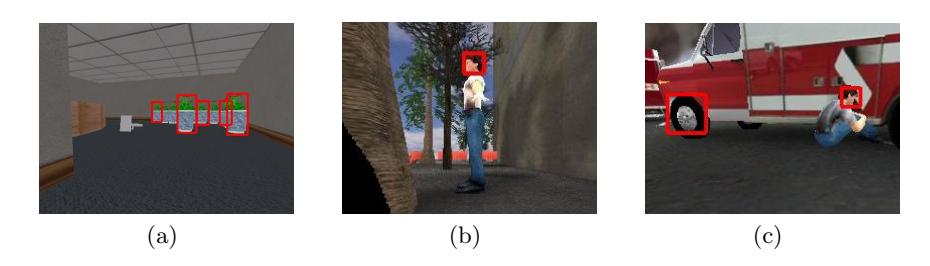
To examine such autonomous recognition, we have implemented an existing object recognition approach that uses a cascade of weak classifiers trained by adaptive boosting to find known objects in a given image [20, 28]. Using several thousand annotated images taken from USARSim, containing victims, plants, chairs and various other objects, we used a cluster at Oxford University's Supercomputing Centre to train our classifiers over several weeks. Initial results led to several false positives (e.g. car wheels were recognised as faces), but by using false positives as negative training examples in later stages of the training, we were able to significantly improve performance: faces and plants now have a detection rate of more than 80%. Also, in several cases our classifier was able to detect victims at greater distance than USARSim's existing VictimSensor. Several examples are shown in Figure 6.
The classifier is still a work in progress, but we hope to integrate it into our existing control software for victim detection. If it performs well, we envision creation of a new open-source VictimSensor for USARSim that uses image recognition instead of the current template based human form detection mechanism [29].
10 Infrastructure developments
The competition is only possible when the simulation infrastructure is available. The creation and validation of this infrastructure should be a shared effort of all teams. This year the following contributions have and will been made by our team:
Battery : Limits the time/power that a robot may use before becoming inactive (Bas Terwijn, 7 points).
ComServer interface : Provides the interface for the external Wireless Simulation Server tool (Bas Terwijn, 7 points).
Fire and Smoke : Environmental model, including the scripts for the sensor response on these effects (Okke Formsma, Nick Dijkshoorn, Sander van Noort, 10 points).
Kenaf : Robot model, including skeletal mesh and behavior scripts (Julian de Hoog, 10 points).
More details about the contributions can be found in our Infrastructure Contribution Plan [30].
11 Conclusion
This paper summarizes improvements in the robot control environment of the Amsterdam Oxford Joint Rescue Team since RoboCup 2009 in Graz. At this competition the third price was won. At the same competition the second place was reached for the Teleoperation Test and the Interleague Challenge. At the RoboCup Iran Open 2010 the USARsim development prize was won.
References
- Balakirsky, S., Carpin, S., Kleiner, A., Lewis, M., Visser, A., Wang, J., Ziparo, V.A.: Towards heterogeneous robot teams for disaster mitigation: Results and Performance Metrics from RoboCup Rescue. Journal of Field Robotics 24 (2007) 943–967
- Visser, A., de Hoog, J.: Amsterdam Oxford Joint Rescue Forces Realistic Simulations to aid research and education in advanced Robot Control algorithms. In: Proc. of the Scientific ICT Research Event Netherlands (SIREN 2008). (2008) 22
- Pfingsthorn, M., Slamet, B., Visser, A., Vlassis, N.: UvA Rescue Team 2006; RoboCup Rescue - Simulation League. In: Proc. CD of the 10th RoboCup International Symposium. (2006)
- Visser, A., Slamet, B., Schmits, T., Gonz´alez Jaime, L.A., Ethembabaoglu, A.: Design decisions of the UvA Rescue 2007 Team on the Challenges of the Virtual Robot competition. In: Proc. 4th International Workshop on Synthetic Simulation and Robotics to Mitigate Earthquake Disaster. (2007) 20–26
- Visser, A., Schmits, T., Roebert, S., de Hoog, J.: Amsterdam Oxford Joint Rescue Forces - Team Description Paper - RoboCup 2008. In: Proc. CD of the 12th RoboCup International Symposium. (2008)
- Visser, A., de Buy Wenniger, G.E.M., Nijhuis, H., Alnajar, F., Huijten, B., van der Velden, M., Josemans, W., Terwijn, B., Walraven, C., Nguyen, Q., Sobolewski, R., Flynn, H., Jankowska, M., de Hoog, J.: Amsterdam Oxford Joint Rescue Forces - Team Description Paper - RoboCup 2009. In: Proc. CD of the 13th RoboCup International Symposium. (2009)
- Alnajar, F., Nijhuis, H., Visser, A.: Coordinated action in a Heterogeneous Rescue Team. In: RoboCup 2009: Robot Soccer World Cup XIII. Volume 5949 of Lecture Notes in Artificial Intelligence., Heidelberg, Springer (2010) 1–10
- Oliehoek, F.A., Visser, A.: A Decision-Theoretic Approach to Collaboration: Principal Description Methods and Efficient Heuristic Approximations. In: Interactive Collaborative Informations Systems. Volume 281 of Studies in Computational Intelligence. Springer-Verlag, Berlin Heidelberg (2010) 87–124
- de Hoog, J., Cameron, S., Visser, A.: Role-based autonomous multi-robot exploration. In: Proceedings of the International Conference on Advanced Cognitive Technologies and Applications (Cognitive 2009). (2009)
- de Hoog, J., Cameron, S., Visser, A.: Selection of rendezvous points for multi-robot exploration in dynamic environments. In: International Conference on Autonomous Agents and Multi-Agent Systems (AAMAS). (2010)
- Nguyen, Q., Visser, A.: A color based rangefinder for an omnidirectional camera. In Balakirsky, S., Carpin, S., Lewis, M., eds.: Proceedings of the International Conference on Intelligent Robots and Systems (IROS 2009), Workshop on Robots, Games, and Research: Success stories in USARSim, IEEE (2009) 41–48
- Schmits, T., Visser, A.: An Omnidirectional Camera Simulation for the USARSim World. In Iocchi, L., Matsubara, H., Weitzenfeld, A., Zhou, C., eds.: RoboCup 2008: Robot Soccer World Cup XII. Volume 5339 of Lecture Notes in Artificial Intelligence., Berlin Heidelberg New York, Springer (2009) 296–307
- van der Velden, M., Josemans, W., Huijten, B., Visser, A.: Application of traversability maps in the virtual rescue competition. In: RoboCup IranOpen 2010 Symposium (RIOS10). (2010)
- Balakirsky, S., Carpin, S., Visser, A.: Evaluation of the robocup 2009 virtual robot rescue competition. In: Proceedings of the 9th Performance Metrics for Intelligent Systems (PERMIS'09) workshop. (2009)
- Balaguer, B., Carpin, S., Balakirsky, S., Visser, A.: Evaluation of robocup maps. In: Proceedings of the 9th Performance Metrics for Intelligent Systems (PERMIS'09) workshop. (2009)
- Balaguer, B., Balakirsky, S., Carpin, S., Visser, A.: Evaluating maps produced by urban search and rescue robots: lessons learned from robocup. Autonomous Robots 27 (2009) 449–464
- Visser, A., Slamet, B.A., Pfingsthorn, M.: Robust weighted scan matching with quadtrees. In: Proc. of the 5th International Workshop on Synthetic Simulation and Robotics to Mitigate Earthquake Disaster (SRMED 2009). (2009)
- Formsma, O., Dijkshoorn, N., van Noort, S., Visser, A.: Realistic simulation of laser range finder behavior in a smoky environment. In: Proceedings CD of the 14th RoboCup International Symposium. (2010) To be published in "RoboCup 2010: Robot Soccer World Cup XIV", Lecture Notes on Artificial Intelligence series, Springer, Heidelberg.
- Sobolewski, R.: Machine learning for automated robot navigation in rough terrain. Master's thesis, University of Oxford (2009)
- Flynn, H.: Machine learning applied to object recognition in robot search and rescue systems. Master's thesis, University of Oxford (2009)
- Jankowska, M.: A hough transform based approach to map stitching. Master's thesis, University of Oxford (2009)
- Pfister, S.T., Kriechbaum, K.L., Roumeliotis, S.I., Burdick, J.W.: Weighted line fitting algorithms for mobile robot map building and efficient data representation. (2003) 1667–1674
- Howard, A., Sukhatme, G.S., Matari´c, M.J.: Multi-robot mapping using manifold representations. Proceedings of the IEEE 94 (2006) 1360–1369
- Maillette de Buy Wenniger, G.E., Schmits, T., Visser, A.: Identifying free space in a robot bird-eye view. In: Proceedings of the 4th European Conference on Mobile Robots (ECMR 2009). (2009)
- Slamet, B.A., Pfingsthorn, M.: ManifoldSLAM: a Multi-Agent Simultaneous Localization and Mapping System for the RoboCup Rescue Virtual Robots Competition. Master's thesis, Universiteit van Amsterdam (2006)
- Birk, A., Carpin, S.: Merging occupancy grid maps from multiple robots. Proceedings of the IEEE 94 (2006) 1384–1397
- Visser, A., Xingrui-Ji, van Ittersum, M., Gonz´alez Jaime, L.A., Stancu, L.A.: Beyond frontier exploration. In: RoboCup 2007: Robot Soccer World Cup XI. Volume 5001 of Lecture Notes in Artificial Intelligence., Springer-Verlag (2008) 113–123
- Flynn, H., de Hoog, J., Cameron, S.: Integrating automated object detection into mapping in USARSim. In: Proceedings of the International Conference on Intelligent Robots and Systems (IROS 2009), Workshop on Robots, Games, and Research: Success stories in USARSim. (2009) 29–34
- Balakirsky, S., Scrapper, C., Carpin, S.: The Evolution of Performance Metrics in the RoboCup Rescue Virtual Robot Competition. In: Proceedings of 2007 Performance Metrics for Intelligent Systems Workshop (PerMIS 2007). (2007) 91–96
- de Hoog, J., Visser, A.: Amsterdam Oxford Joint Rescue Forces: Infrastructure Contribution Plan (2010) Published online.