MRL Team Description Paper for Virtual Robots Competition 2013
Sanaz Taleghani, Mohammad Hossein Shayesteh, Saeid Samizade, Fatemeh Sistani, Sara Hashemi, Atoosa Hashemi, Jalal Najafi
Islamic Azad University of Qazvin, Electrical, IT & Computer Sciences Department, Mechatronics Research Lab, Qazvin, Iran
http://www.ros.org/wiki/navigation
Abstract This paper describes a short review of the MRL team's work developed for participating in RoboCup2013 Virtual Robots Competitions. It includes parts such as SLAM, Autonomous Exploration, Multi Agent Coordination and Exploration, Robot Control, Image Enhancement, ROS.
1 Introduction
Nowadays Robotic and Artificial Intelligence are in the center of attention of many researchers. USARSim provides us with an environment in which the conjunction of these two fields occurs. In this environment, a disaster is being simulated in indoor and outdoor scenarios. The goal is to gather a map of unknown environment which would provide information about the situation, victims. To overcome the goal, a combination of the state of the art algorithms of different fields needs to be implemented. These fields include Localization, Mapping, Image Processing, Robot Navigation, Robot Communication and Control, Multi-Robot Exploration and Coordination.
Our team members and their contributions in team are:
SLAM : Sanaz Taleghani, Mohsen Akbari
Autonamous Exploration : Mohammad.H Shayesteh, Sanaz Taleghani, Sara
Heshemi
Multi Agent Exploration : Saeid Samizade, Mohammad.H Shayesteh, Fatemeh
Sistani
Control of mobile robot : Jalal Najafi, Saeid Samizade Image Enhancement : Sara Hashemi, Atoosa Hashemi
ROS : Mohammad.H Shayesteh, Atoosa Hashemi
2 Localization and Mapping
We have implemented ICEG [1] as Scan matching method and Grid Mapping in previous competitions. This year we are working some improved Techniques such as Particle Filters for improving the estimation in this algorithm.
3 Autonomous Exploration
Two main phases of Autonomous Exploration algorithm are Path planning and obstacle avoidance. We have implemented RRT-connect motion planning that is faster than basic RRT algorithm and it is suitable for online application.
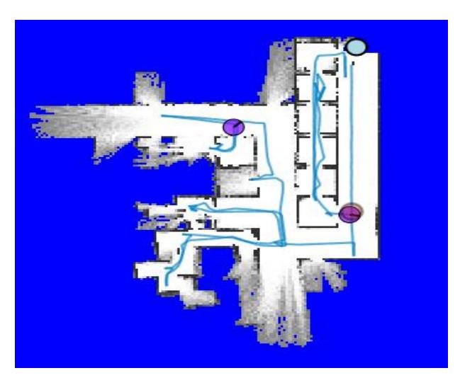
For obstacle avoidance the robot perceives its environment of several sonar sensors. The Switching path-planning control scheme is used for detecting collision. In this scheme, the robot can gradually approach its target according to the motion tracking mode, obstacle avoidance mode, self-rotation mode, and robot state selection designed by learning and expert rules for enhancing the tracking speed and adapting to different environments [2]. Fig.1 illustrates the result of RRT-Connect motion tracking with mentioned schema.
4 Multi Agent Exploration
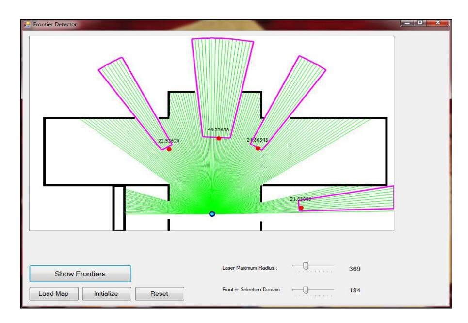
We design a frontier based method [3] for multi a gent exploration. When a robot performs frontier detecting process, it uses the range scan data and detects each sequence of laser beams that return a distance more than a specific value, as a frontier and put frontiers location between the sequence's start and end. After it guess a weight for each frontier with three Parameters such as (
where of frontier degree, A parameter is free area to explore the frontier behind and D parameter is the size of the entrance. See Figure 2.
$$W_f = W_0 + W_1 \theta + W_2 D + W_3 A$$
Where to are constant values. After visiting the frontier by a robot, its real weight will calculate and replace. We decided to minimize the subtraction between new value and old value by adjusting to such that this problem can solve easily by LMSE (Least Mean Square Error) algorithm [4]. The method applied in LMSE, initialization frontiers weight are based on expert knowledge. Also weight can be calculated based on the mechanisms that have been proposed by visser et.al [5]
Our method is a tree based that manages robots movement in the map. In this method, each frontier will be represented by a node and each path between frontiers with an edge. The blue circle in Fig 3 is the initial location of the robots when spawn near BS. This is root of the tree.
We assume a level for each node. The Level of root is always zero. Each frontier can be detected from a visited frontier that is its child. The level of a child is 1 unit more than its parent's level.
For example, in Fig 3. , , have same one level, , have same level with two number and frontier can be detected from but in this case, the parent level is less known as the main parent. It means that the level of is 2.
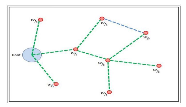
As mentioned in the previous section, the robot after detecting new frontiers, calculates the weight with parameters. Since Robot visits the frontier, its weight is calculated according to the conditions. Our measure is the total weight of new frontiers that are obtained from it (children frontiers are unvisited). After it, all parent frontiers to root will be updated by the formula below. This formula proved as a reinforcement learning method [6].
$$w_{p_{f_i}} = w_{p_{f_i}} + \alpha \left[ w'{f_i} - w{f_i} \right]$$
Where α is a float constant value between 0 and 1 and known as learning rate. For example in Fig 1 if =80 , after the explored total weight of , , is given as . Thus if are more than 80, a positive value is added to , and this effect will be reduced to the root.
Robots will extend the tree during exploration. Each branch continues to explore the map such that the tree extends with the highest rate and Information sharing quickly between agents.
5 Robot Control
One of the simplest mobile robot constructions is a chassis with two fixed wheels. Understanding this construction helps you to grasp some basic kinematics of car-like robots. Usually differential drive mobile robots have an additional castor wheel as the third fulcrum. It is usually used for stability. Sometimes roller-balls can be used but from the kinematics point of view, there are no differences in calculations.
As it can rotate freely in all directions, in our calculation we can omit the castor wheel because it only has a very little influence over the robot's kinematics In case of differential drive, to avoid slippage and have only a pure rolling motion, the robot must rotate around a point that lies on the common axis of the two driving wheels [7]. This point is known as the instantaneous center of curvature (ICC) or the instantaneous center of rotation (ICR). By changing the velocities of the two wheels, the instantaneous center of rotation will move and different trajectories will be followed (Fig. 4) [8].
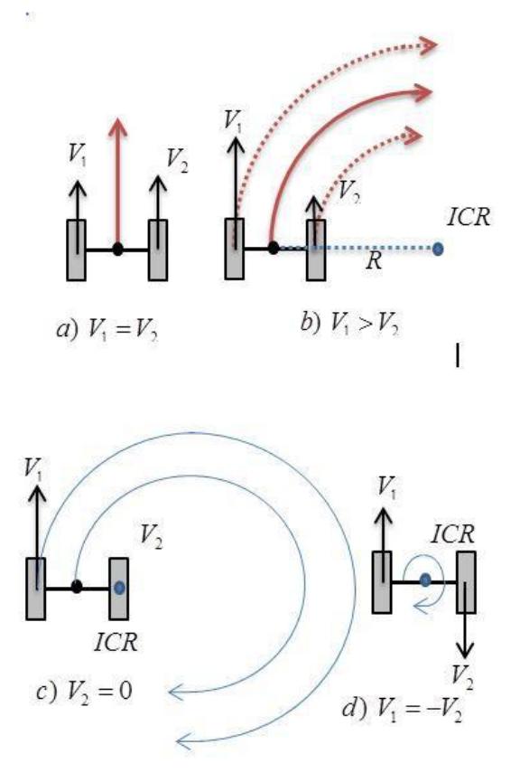
Where v1 is the left wheel's velocity along the ground, and v2 is the right wheel's velocity along the ground, and R is the signed distance from the ICR to the midpoint between the two wheels. When v1and v2 were calculated, four states occurred (fig 4). If v1 and v2 are equal then the robot moves in a straight line (see Fig. 4a). For different values of v1 and v2, the mobile robot does not move in a straight line but rather follows a curved trajectory around a point located at a distance R from CR (Fig. 4b), changing both the robot's position and orientation.
If one of the wheel's velocity is zeros the robot turning around wheel which has zeros velocity and follows a circle trajectory (Fig 4c). If v1 = -v2, then the radius R is zero and the robot rotates around ICR (it rotates in place Fig. 4d).
6 ROS
One of the most important challenges in autonomous and multi agent systems is complexity in low level modules. These kinds of problems have big effects on performance of your system in different situations. There are many solutions for these problems. One way is using from standard packages for lower layers such as ROS (Robot Operation System) packages. This package as been used in Mapping, Navigation and control modules.
Using of the ROS in virtual robot simulation needs to a wrapper and interface application such as USARSim/ROS [9,10]. As shown in Fig. 5, USARSim/ROS is used in Com Station for mapping and navigation modules.
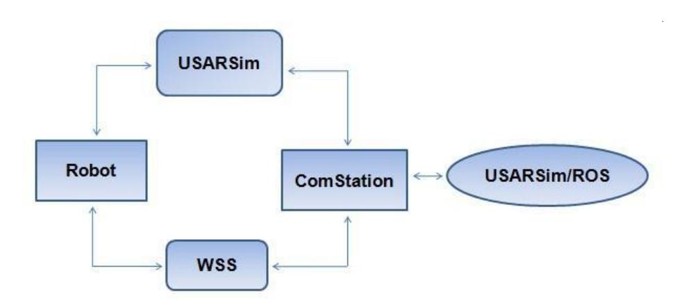
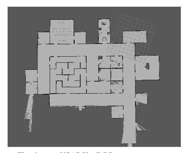
The robot send its data to WSS, then Com Station receives these data and gives them to USARSim/ROS; Finally USARSim/ROS package generates the map and navigation decisions. As shown in Fig. 6, the map has been generated by Gmapping package.
7 Image Enhancement
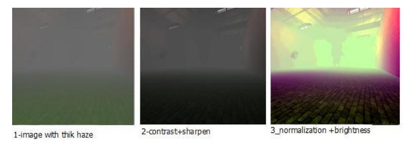
Since the realization of received images from smoky environment with low contrast is hard, for solving this problem we tested several algorithms such as contrast, sharpen, etc that among them equalization and normalization have best results. Equalization algorithm increases contrast in image but does not normalize values ,it is good reason for using histogram normalization.
8 Conclusion
In this paper we summarized the main features of MRL team developed for participating in Robocop competition 2013. We improved on Autonomous challenges, Image enhancement, control of robot and other different methods are still in progress.
References
- Taleghani, S., Sharbafi M.A., Haghighat, A.T., Esmaeili, E., :ICE Matching, a Robust Mobile Robot Localization with Application to SLAM: ICTAI 2010, Aras, France. (2010)
- Wain, R. J., Liu, C. M., Lin, Y. W., :Design of switching path-planning control for obstacle avoidance of mobile robot. Journal of the Franklin Institute, pp. 718- 737, Feb. 2011.
- Yamauchi, B. : Frontier-based exploration using multiple robots: In Proceedings of the International Conference on Autonomous Agents (AGENTS), pages 47 - 53, New York, NY, USA, 1998. ACM.
- Alpaydin, E. :Introduction to Machine Learning:2nd edition: MIT Press, 2010.
- Visser, A., Ji, X., Van Ittersum, M., Gonzalez Jaime, L.A., A. Stancu, L. :Beyond frontier exploration: In RoboCup 2007: Robot Soccer World Cup XI, (edited by U. Visser, F. Ribeiro, T. Ohashi, F. Dellaert), Lecture Notes on Artificial Intelligence series, volume 5001, p. 113-123,Springer, Berlin Heidelberg New York, July 2008.
- Sutton, R. , Barto, A. :Reinforcement Learning: An Introduction, MIT Press, Cambridge
- LaValle, S. : PLANNING ALGORITHMS, Cambridge University Press,2006, Cambridge
- Hellström, T. : Kinematics Equations for Differential Drive and Articulated Steering, Dec 19, 2011 UMINF-11.19 ISSN-0348-0542
- Marder Eppstein , E., 2011. "ROS Navigation Stack". http://www.ros.org/wiki/navigation.
- Balakirsky, S., Kootbally, Z. :USARSim/ROS: A Combined Framework for Robotic Control and Simulation :ISFA 2012, Proceedings of the ASME 2012 International Symposium on Flexible Automation, St. Louis, June 18-20, 2012.