JoiTech Team Description
Yuji Oshima, Shun Kitamura, Kenji Doi, Kohei Suga, Takashi Takuma, Kazuaki Tanaka, Hiroki Mori, Minoru Asada
Adaptive Machine Systems, Graduate School of Engineering, Osaka University, Osaka, Japan; Mechanical Engineering, Factory of Engineering, Osaka Institute of Technology, Osaka, Japan; Dept. of Electrical and Electronic Systems Engineering, Osaka Institute of Technology, Osaka, Japan; Dept. of Mechanical Engineering, Osaka Institute of Technology, Osaka, Japan
Abstract In this paper, we describe the structure of our humanoid robot soccer team JoiTech to participate in the RoboCup 2012 AdultSize Humanoid League competition. Our team gathers two universities in Osaka, Japan, that is Osaka University and Osaka Institute of Technology. The platform named Tichno-RN was developed by Vstone. It consists of 22 degrees of freedom, fully electronically actuated, and several sensors, such as image sensor, 2-axis gyro sensors, 3-axis acceleration sensors, and potentio meters. The software architecture consists of the modules of image capture, image recognition, localization of the ball and the goals, decision making, motor controls and so on.
Introduction
Team JoiTech is originally derived from RoboCup team JEAP, which participated in competitions of Humanoid League KidSize class since 2006. Team JEAP is composed of master's and doctoral students at Emergent Robotics Laboratory, Osaka university. Team JoiTech is a derivative of team JEAP, and we started up a new team in cooperation with students at Osaka Institute of Technology since RoboCup JAPAN OPEN 2010. The team name, JoiTech, is an acronym for "JEAP and Osaka Institute of Technology", and it also means "joint team with Osaka Inst. of Technology" and "enjoy technology".
The main goal of our lab is to understand the cognitive developmental process of humans based on synthetic approaches with humanoids. Our lab adopted an adult sized robot, Tichno-RN, which is a good testbed for this purpose. One of the research issues is advanced dynamic biped walking. In this paper, we describe hardware specifications in section 2, and the software specifications is described in section 3.
Robot Hardware
In this section, we describe hardware specifications of Tichno-RN. Mechanical structure of Tichno-RN was developed by Vstone Co.,Ltd. The remarkable features of this robot are its smoothly fast movements even its size and fully autonomation based on sensory information. The electronic motors of Tichno-RN are developed in order to generate stronger torque stably. The covers of the motors are made of aluminum and help the dissipation of the motor heat. Therefore, they can stay in action during the game without breaking down. Each actuator has a microcontroller and communicate with the main controller through serial connections. It enables the main controller to receive various information: angular position of each joint, temperature, and speed.
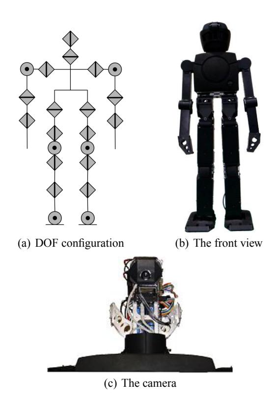
The front view and schematic overview are shown in Fig.1. Tichno-RN has 22 degrees of freedom. Its detailed specification is given in Table1.
Tichno-RN hardware specifications
| Tichno-RN | ||
|---|---|---|
| Height (mm) | 1400 | |
| Weight (kg) | 25 | |
| DOF | 22 | |
| Actuators | VS-SV410, VS-SV1150, VS-SV3310 | |
| Camera Type | SenTech STC-C33USB-BTL | |
| Controller | Main Controller | Sub Controller |
| CPU | Panasonic Let's NOTE | VS-RC003HV |
| Core2Duo 1.6GHz | ARM7TDMI LPC2148 | |
| ROM | 222 GB (HDD) | 512 KB |
| RAM | 2 GB | 40 MB |
| OS | Windows7 | None |
Modular software environment
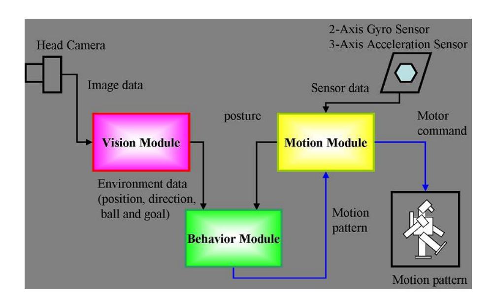
The software of the robot consists of three modules: the vision, the motion, and the behavior modules. These three modules perform in parallel during the game. The vision and behavior modules are programmed on the main controller. The motion module works on the sub controller.
Fig.2 shows the overall system of the software. The vision module detects positions and directions of the ball, the goals and itself from image data. The behavior module selects an appropriate pattern of motions based on information from vision module. The motion module memorizes the motor repertoires coded as joint angles. The motor commands are selected based on the orders from the behavior module, and are executed by motors.
The rest of this paper is the explanation of each modules
Vision Module
The vision module has two functions: detecting of objects and self-localization. This module sends the environmental information (e.g., the location of the ball, the goal, and the robot), which are processed from image data captured by the camera, to the behavior module. At first, areas of objects are detected by image processing. Secondly, the selflocation and distance between the robot and the ball and the goals are calculated.
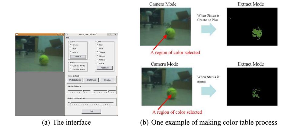
Detection of objects We developed a library for the image processing as a vision module. Since the luminance and pixel values of colors sometimes change because of the shadow and lighting condition, it is necessary for robot to know the range of color variation. For this purpose, we implemented a GUI application for setting color variation in vision module (see Fig. 3(a)). By using this system, we can make a color table by adding or subtracting the range of the values of pixels before the game (see Fig. 3(b)). The robot uses it during the game and detects the areas of objects robustly.
Vision Module (continued)
Self-localization We are developing self-localization system using field lines based on the Particle filter algorithm. This filter is widely used to detect self-position for the mobile robots (e.g., [2], [3]). In our system, robot's location is estimated in the following procedure:
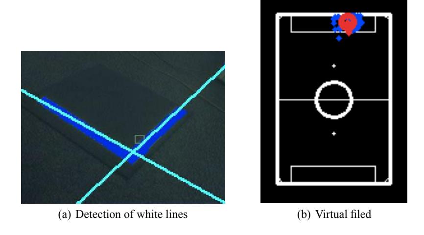
- The robot detects the white lines by Hough transform algorithm[1]. Fig. 4(a) shows the result of the line-detection system. This algorithm transforms groups of white-colored pixels in a image to the lines.
- The likelihood in each particles set in the virtual field is calculated.
The particles in the virtual field are shown in Fig. 4(b). The small dots and the red circle are the particles and the robot's position, respectively. The robot's location is calculated as a average of location of particles. The likelihood is solved by the similarity between the captured lines and the calculated lines in the virtual field.
- The particles are moved toward the particle with the most likelihood.
- Step 2 and 3 are repeated until convergence.
Behavior Module
The behavior module determines an appropriate motion out of the motor repertoires depending on the environmental information, the self-posture.
The behavior module sequentially receives the information of the field (the ball, the goals and its own location and posture) from the postural sensors and the vision modules. Tichno-RN has the 2-axis gyro and 3-axis acceleration sensors. The robot's postural information whether robot is down or not is detected by threshold processing of these sensory data. Furthermore, the behavior module transmits and receives the environmental information via UDP communication. This communication enable the robot to act cooperatively. Based on the information, the robot selects an appropriate motion from motor repertoires, such as kicking, walking, throwing, and so on.
These plans of the motions can be changed depending on roles of the robots. We assign the role (goalkeeper, offence or defence) to each robot.
Motion Module
The motion module receives the order of motions from the behavior module, and submits its motor commands (i.e., joint angles) to the motors. This module memorizes motor repertoires which consist of patterns of joint angles.
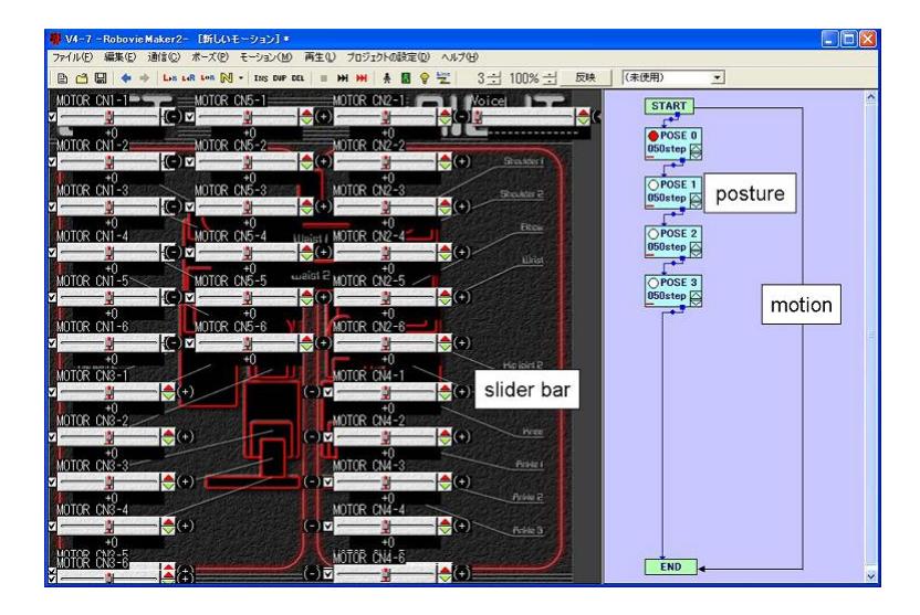
In order to create these motor repertoires, we use RobovieMaker, which is a software developed by Vstone. Fig. 5 shows the development environment by RobovieMaker. Each value of slider bars corresponds to the joint angles of the motors. Robot's postures are made by these slider bars. The box on the left side means a postural data. These boxes are linked like flowchart to create the motions. The postures between the postures made by the slider bars are automatically interpolated. The RobovieMaker enables us to create the motions more easily.
Conclusion
We have described the hardware and software features of our robot to be used for the competition in Mexico. Last year, we won the first prise of the Technical Challenge. This year we focus on development of self-localization system to enable the robot to get better performance.
References
- R.O. Duda and P.E. Hart. Use of the hough transformation to detect lines and curves in pictures. Communications of the ACM, 15(1):11–15, 1972.
- D. Fox, S. Thrun, F. Dellaert, and W. Burgard. Particle filters for mobile robot localization. In A. Doucet, N. de Freitas, and N. Gordon, editors, Sequential Monte Carlo Methods in Practice. Springer Verlag, New York, 2000.
- T. Rofer, T. Laue, and D. Thomas. Particle-filter-based self-localization using landmarks and directed lines. RoboCup 2005: Robot Soccer World Cup IX, pages 608–615, 2006.