RoboCup 2009 Humanoid KidSize — Robo Noble Team
Hamid Reza Sharifany, Majid Esmaeili, Morteza Hadad
"Ostad Taher" institute Azad University of Majlesi
Abstract This paper describes stages of designing and making kidsize robot in order to presenting in international robocup 2009 competition. This robot in addition to having the capacity of taking part in robocup competitions, includes other new features such as running and going up the stairs which is the first in Iran. In mechanic part robot has highest degree of freedom by utilizing 28 ServoMotors. In electronic part, gyroscope sensor is used in order to having highest level of equilibrium while moving and running. Also software control of robot includes two parts: part one is software control of robot and the other one is the control by external processor which is sent to robot wirelessly.
Key words: Gyroscope, LabVIEW, Microcontroller, Image processing
1. Introduction
Robo Noble team designed and made a kidsize robot in order to presenting in robocup international competitions which stages of making it is described in this paper. This paper includes description of electronic components, mechanic and programming of robot.
2. Robot Mechanic
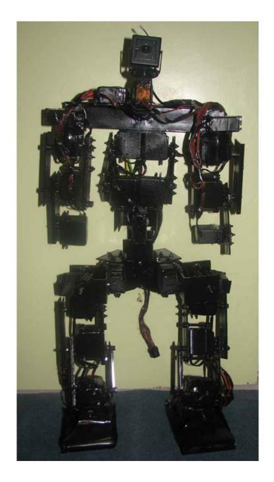
Aluminum joints were used in main body of robot because of its low weight and high strength. Most of robot joints are mobile and general weight of robot is on the ServoMotors. Regarding the design of robot in order to gaining highest level of freedom, 28 ServoMotors were used in joints. The most numbers of ServoMotors were used in designing the foot, so that it can do most human like motions and can behave in all directions as instructions. Figure 1 shows a general view of robot designing and making.
Robot features: Height: 58cm Width: 28cm Weight: 4900 g
2.1. Operators
In this project ServoMotors are operators. Motors responding error signal quickly and accelerating charge rapidly are called ServoMotors. Ratio of torque to Inertia (T/J) is one significant feature of ServoMotor, since motor accelerates by this factor.
Basic features of each ServoMotor include:
- 2.1.1. Output torque of motor must be proportionate to used voltage.
- 2.1.2. Torque direction of ServoMotor must be dependent to momentary polarity of control voltage.
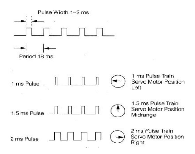
ServoMotors used in this project are gearbox DC motors with feedback of situation control. Motor shaft can rotate 180° and is controlled by microcontroller with variable width pulses. This pulse signal causes motor shaft be between +/-90°. Pulses range from 1 to 2 ms. As it is shown in figure 2, pulse 1ms rotates shaft to left and pulse 2 ms rotates it to right.
3. Robot Electronic
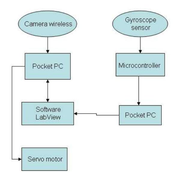
Robot electronic includes microcontrollers, sensors, analog to digital transformers and ServoMotors. Microcontrollers series Mega 8 by Atmel Company was used for providing appropriate motional situation for robot and microcontrollers programmed by Codevision software. Figure 4 shows the relationship between different parts of robot. In the following it is described that how sensors, USB to Serial transformers and robot power supply work.
3.1. Sensors
3.1.1. Camera Sensor
This sensor was used in order to processing of surrounding environment. The features of camera can be seen in table 1. Camera sensor includes three parts: camera, capture card and wireless system which works in 2.4 GHz frequency.
Table 1 - features of camera located on the robot
| Item | Unit | Value |
|---|---|---|
| Imaging Sensor | Inch | 1/3 – inch CMOS |
| CMOS Total Pixels | Pixels | 628* 582(PAL) |
| View Angle | Degree | 62 |
| Minimum Illumination | Lux | 1. 5 Lux/F 1. 5 |
| Video Gain Control | Automatic | |
| Ferequency | MHz | 2. 4 |
| Transmission Power | mw | 10 |
| Modulation Mode | FM | |
| Power Supply(for Receiver & Camera) | V dc | 12 V – 8 V |
3.1.2. Gyroscope Sensor
This sensor was used in order to keeping robot equilibrium in different situations.
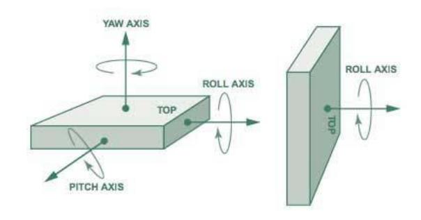
It works based on situations change against initial state and shows changes in output in the form of analog. Digital values are entered to microcontroller by A/D transformer and are transmitted to computer, processing is performed according to changes momently and again required commands are transmitted form computer to robot. In figure 5 it can be seen how sensor works upon three shown axis:
1- Yaw Axis 2- Pitch Axis 3- Roll Axis
3.2. Robot power supply
It was used in order to producing power needed for robot and the circuits by 28 rechargeable batteries (Lithium-ion) features of which can be found in table 4.
Table 4 - feature of battery used for robot supply
| Model | KLI18650 (2000) |
|---|---|
| Description | Lithium-Ion rechargeable battery |
| Nominal Capacity | 2000 mAh at 400mA rate discharge |
| Nominal Voltage | 3.7 Volt |
| Cut-Off Voltage | 2.7 Volt |
| Weight | 46 gram |
| Life Duration | Over 300 (Typ. 500) cycles at 400mA discharge to 2.7V |
| Charge | Using dedicated CC/CV (4.2V) battery charger only |
| Trickle | 67-100 mA |
| Standard | 1000 mA x 5 hours |
| Quick | 2000 mA x 2.5 hours |
| Temperature Environment | Standard charge - 0 degC to 45 degC |
| Discharge | -20 degC to 60 degC |
| Storage | -20 degC to 45 degC |
4. Robot programming
LabVIEW software was used for programming of robot. It was selected based on its ability in processing and easy communication with computer external environment and its graphic facilities and suitable programming. It was utilized also for performing two main tasks:
4.1. Image processing
4.2. Communicating with USB port for Data processing
Photos captured by camera are sent to capture card. Capture card which is connected to USB, transmits received data to computer. Now LabVIEW takes this data and at first transforms them to grayscale and then performs image processing. Meanwhile Gyroscope data is also sent to computer. LabVIEW gets this data too and after comparison and integrating with image processing data, required output, that is data related to Servo Motors control and moving robot toward ball and goal, is transmitted to USB port, to which interface of USB to Serial is connected. It transforms data to Serial format and sends them to robot. This operation is done continually and the state of "Real Time" of robot increases.
5. Conclusion
The important point in making Humanoid robot is keeping equilibrium of robot is different motional situations which this goal can be achieved by using gyroscope sensor and also commands must be sent to robot simultaneously, that is motion must be commanded in parallel. But in computer systems operations are series that make difficult controlling robot while moving. The more the numbers of joints in human like robot and the more degree of freedom, there is more flexibility and Real Time in robot.
Acknowledgment
Robo Noble team thank Mr.Mohammad Jali, manager of "Ostad Taher" institute for providing suitable situation for designing and making humanoid robot, and also technical and performing committee of international robocup 2009 competition.
References
- AVR & CodeVision
- www.NI.com
- www.Alldatasheet.com
- www.hoperf.com
- Atmel datasheet
- Image Acquisition and Processing With LabVIEW
- Image Processing With LabVIEW and IMAQ Vision