aiRobot: Team Description for Humanoid KidSize League of RoboCup 2009
Tzuu-Hseng S. Li, Yu Te Su, Chun-Ming Chang, Shao-Wei Lai, Kiah-Yang Chong, Te-Kai Wang
aiRobots Laboratory, Department of Electrical Engineering, National Cheng Kung University, Tainan, Taiwan 70101, R.O.C.
Abstract This paper is about the construction and functions of aiRobot-III, which has 21 degrees of freedom as well as frontal camera, PDA, 3-axis accelerometer and a digital compass. As for robot motion, we design a motion control interface to implement various behaviors. First, the architecture of aiRobot-III is introduced. Then the detail hardware specification is described. Finally, some experiments show that aiRobot-III is a multifunctional intelligent humanoid robot.
1. Introduction
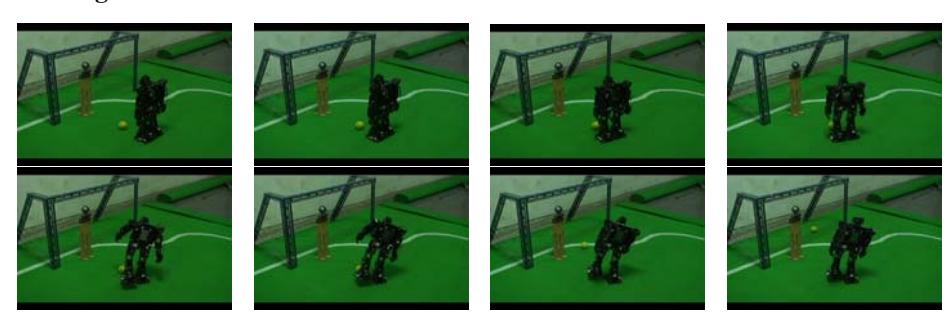
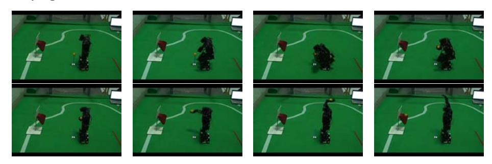
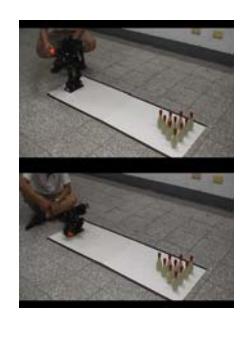
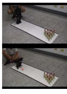
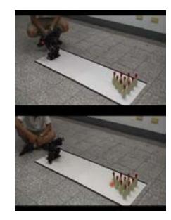
In the humanoid league, many technology problems should be solved by integrating various field of science, such as mechanic design, computer science, and biotechnology. In order to challenge the ultimate of humanoid robot, we design and implement the aiRobot-III [1,2]. The architecture and hardware specification of aiRobot-III are introduced in Section 2 and Section 3, respectively. To design aiRobot-III, we aim to develop a multifunctional robot, which can not only play soccer but also play some other events. For this reason, aiRobot-III will perform the ability to play basketball and bowing and will be demonstrated in the last section.
2. The Architecture of aiRobot-III
The photo of aiRobot-III is shown in Fig. 1. Table 1 shows the basic specification of the robot. All the information of sensors are delivered to the strategy and motion control system. After the analyzing the data, the actuators act according to the strategy. The system module of the aiRobot-III includes: strategy and motion control system, actuator module, visual system and multi-sensors module, and will be described in the following section.
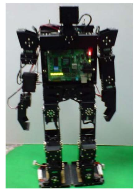
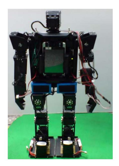
Table 1. Basic specification of aiRobot-III
| Height [mm] | 550 |
|---|---|
| Width [mm] | 234 |
| Depth [mm] | 123 |
| Weight | 3.2kg |
3. The hardware of aiRobot-III
The hardware of aiRobot-III can be divided into four system modules: strategy and motion control system, actuator module, visual system and multi-sensors module.
Strategy and motion control system
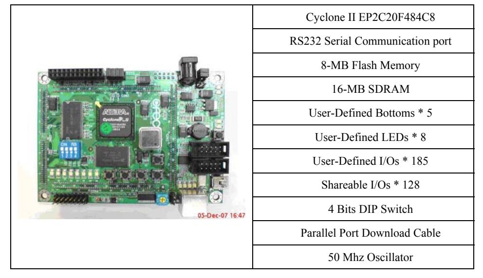
For the operating core of aiRobot-III, we adopt NIOS II Cyclone II evaluation board produced by Altera. Table 2 lists the feature and the picture of the NIOS II board. It is an embedded programmable system. With the built-in SOPC Builder in the Altera Quartus II software, we can design the whole hardware structure of aiRobot-III by ourselves. It can help us to determine the clock rate and build up the system timer and UART module in NIOS CPU. After generating the system via SOPC Builder, we can use Verilog hardware description language (Verilog HDL) to synthesize the circuits for motors and sensors with FPGA logic gates. Finally, we design our C/C++ application code with the NIOS II IDE (Integrated Development Environment) to implement some components of control system, such as fuzzy controller and intelligent strategy.
Actuator module
The actuators used in aiRobot-III are the products of Robotis [3]. The internal data, such as position, velocity and feedback signal are accessible. Therefore, we can not only do position control but also velocity control. We use four kinds of motors to control all the motion of aiRobot-III. The assignment of these motors can be obtained by Table 3.
Table 3. The assignment of motors
| Joint(freedom of degree) | Motor model |
|---|---|
| Head(2), Shoulders(4), Arms(4) | AX-12 |
| Hips(5) | RX-28 |
| Knees(2) | RX-64 |
| Ankles(4) | RX-28 |
Visual system
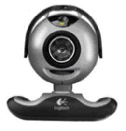
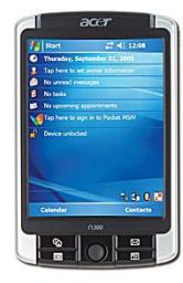
The visual system can be divided into two parts: image capture device and image processing center. We use Logitech QuickCam Pro5000 and a PDA of ACER N300 as the image capture device and image processing center, respectively. The appearance of visual system is depicted in Fig. 2.
Multi-sensors module
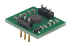
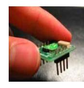
For intensifying the robustness and stability, the robot must adapt itself from external disturbances. We place an accelerometer and a digital compass in its body. Fig. 3 illustrates the pictures of tri-axes accelerometer Hitachi H48C [4] and digital compass TDCM3 [5].
4. Ability Demonstration
Kicking ball
Playing basketball
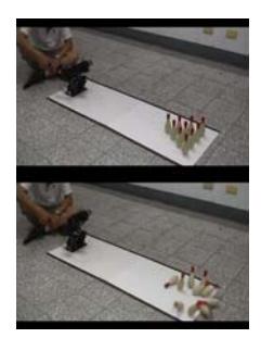
Playing Bowling
Conclusion
Our humanoid robot, aiRobot-III, possesses 21 degrees of freedom and adopts NIOS II evaluation board as the strategy and control motion system. The visual system and multi-sensors module are also introduced. We integrate these system modules and implement the full autonomous humanoid robot. Finally, the experimental results indicate that the robot can perform and accomplish various tasks.
References
- Y.-T. Su, C.-Y. Hu, M. F. Lu, C.-M. Chang, S.-W. Lai, S.-H. Liu, and Tzuu-Hseng S. Li, "Design and implementation of SOPC based image and control system for HuroCup," J. of Harbin Institute Tech. (New Series), Vol. 15, pp.41-46, September 2008 China.
- M.-C. Kao, K.-Y. Chong, P.-J. Kuo, C.-C. Sun, and Tzuu-Hseng S. Li, 2008. "Design of vision and strategy system for 2008 AndroSot," J. of Harbin Institute Tech. (New Series), Vol. 15, pp.35-40, September 2008 China.
- http://www.robotis.com/zbxe/dynamixel_en
- http://www.parallax.com/Store/Sensors/AccelerationTilt/tabid/172/CategoryID/47/List/0/Level/a/ProductID/97/Default.aspx?SortField=ProductName%2CProductName
- http://www.topteamnavigation.com.tw/eng/tdcm3ok.htm