Team Description Paper
Kao-Shing Hwang, Li-Hao Chen, Yen-Hung Chen, Chen-Fu Li, Te-Ju Kung, Ling-Wen Wang, Chia-Hao Hsu
EIS Laboratory, Department of Electrical Engineering National Chung Cheng University, Chiay, Taiwan, 62102, ROC
Abstract This paper describes the mechanical, electrical and software design of the humanoid robot systems by CCU EE in KidSize competition RoboCup. In mechanic part robot has highest degree of freedom by utilizing Servo Motors of AX-12, and we use Openmoko to process our images that caught by camera. In electronic part, G-sensor of Openmoko is used in order to having highest level of equilibrium while fallen down. Also software control of robot uses the DsPIC to control the robot's behaviors and connect to the bridge using RF signals.
1 Introduction
In the humanoid field, it needs to integrate various field of technology, such as mechanical design, computer science, and biotechnology. This robot is very complicated in different parts including designing and building mechanics, hardware and software and some other advanced connection. Our team has research more than 2 years on humanoid robots in EIS laboratory in Chung Cheng University. The continuation of this paper deals with different parts of robot and the features of each part.
2 Mechanical Designs
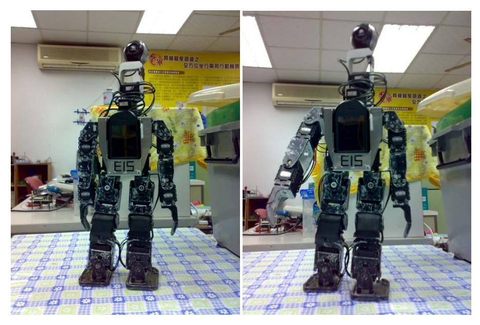
The skeleton of EIS Robot is used the original and add some changes. We use two motors with the camera to be the humanoid's eyes instead of the original one.
Actuators are all servos, though diversified in Torque and Speed. In these robots weight and actuators are well distributed to meet the rigor requirement of biped robot. EIS Robot is driven by 20 servo motors: 5 in each leg, 2 of which constitute ankle joint, 1 in knee joint and 2 in hip joint; 2 in waist; 3 in each arm and 2 in neck. We use two motors to increase the angle of view, and then help our Humanoid robot to find and catch the ball and goal.
We use Openmoko to process images. All these DOF allow flexible movement, and fulfill the locomotion request. Figure 1 shows the outline of EIS Robot.
3 Electronic Designs
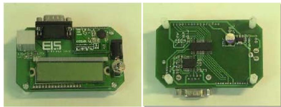
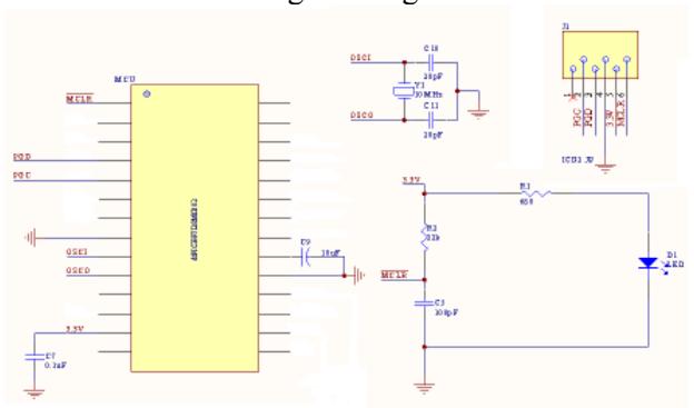
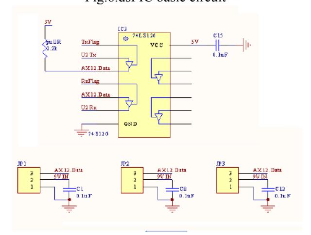
We use the development board that developed by the seniors to be the controller of our robot. We send the RF signals from the bridge to our dsPIC on the robot. The Bridge provides a way to connect two interfaces, RS232 and wireless RF. What the bridge should do is very simple, to receive the message from host terminal by RS232 and transmit through wireless RF, vice versa. The MAX232 is an integrated circuit that converts signals from an RS232 serial port to signals suitable for use in TTL compatible digital logic circuits. The drivers provide RS-232 voltage level outputs (approx. ± 7.5 V) from a single + 5 V supply via on-chip charge pumps and external capacitors. This makes it useful for implementing RS-232 in devices that otherwise do not need any voltages outside the 0 V to + 5 V range, as power supply design does not need to be made more complicated just for driving the RS-232 in this case.
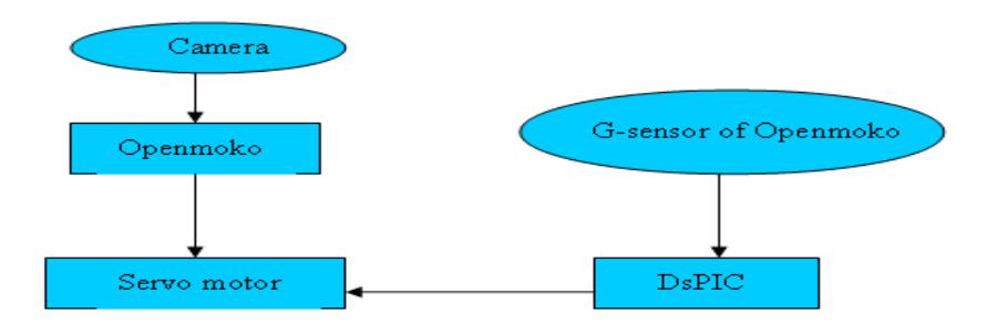
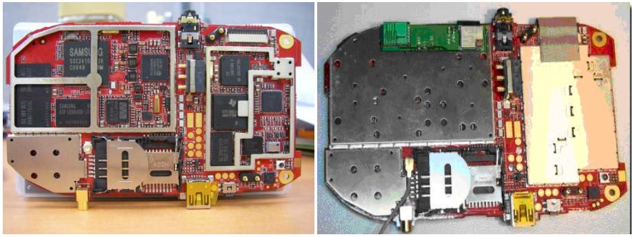
And we also used G-sensor of Openmoko to determine the position of our robot when it fallen down to remind the controller sending the instructions to make the robot stand up.

4 Software Designs
- Hardware Interface-contains all low level routines to access hardware of the robot including sensors and actuators.
- Vision-the images are caught and read by our camera, then give these images data to the openmoko let openmoko to process images.
- Strategy-
- Step 1: robot search the target by rotating the camera
- Step 2: if there is no target have been found, then change the position and repeat the step 1.
- Step 3: if there is goal have been found, go straight to the target, and kick the ball to the goal.
5 Conclusions
In our some other competitions, we realize that we can improve our mechanical, electronic and some other control features, so the robot may perform more stable, more robust also. We changed some origin mechanical design, and now we are ready to achieve a better result.
This project made us realize how complexity in human nature. We need to consider not only the robot body architecture, but also the behavior of robot. To earn more knowledge in robot field, we search lots of information, it let us discover our different capabilities and our weakness.
At the time of writing, January 22th, 2010, we made good progress in preparation for the competition, and now we will continue improving our system and the robustness of the robot for RoboCup 2010.
References
[1] Ching-Yu Liao, "Design of a Hierarchical Architecture for a Modularized Low-cost Embedded System –an Implementation of multi-robot systems" [2] Bioloid-http://www.idminer.com.tw/cubekm/front/bin/cglist.phtml?Category=58 [3] Openmoko-http://wiki.openmoko.org/wiki/Main_Page