SitiK KIT — Team Description for the Humanoid KidSize League of RoboCup 2010
Shohei Takesako, Nasuka Awai, Kei Sugawara, Hideo Hattori, Yuichiro Hirai, Takesi Miyata, Keisuke Urushibata, Tomoya Oniyama, Youhei Nisino, Kentaro Makimoto, Satoru Masuyama, Kouta Yamazaki, Yasuki Asano, Kosei Demura
Factory for Dreams and Ideas. Kanazawa Institute of Technology 7-1 Ohgigaoka, Nonoichi, Ishikawa 921-8501, Japan; Department of Robotics, Kanazawa Institute of Technology 7-1 Ohgigaoka, Nonoichi, Ishikawa 921-8501, Japan
Abstract This paper describes a hardware and software system on the KidSize humanoid robots of the team SitiK in RoboCup 2010. These robots are about 56cm tall and 4.3kg in weight, and equipped directional cameras, acceleration and gyroscope, tiny laptop computers (SONY, VAIO Type U), Microcomputer (Microchip Technology Inc. , PIC 30F3012) and have 20 DOFs. These big and heavy robots are designed and made by ourselves that can perform a physically strong play. The robot can walk 1.5 times faster and more stabilize compared with our old robots.
1 Introduction
Kanazawa Institute of Technology, KIT, established Yumekobo to encourage students to create things and make character building in 1993 [1]. The most important activity of Yumekobo is to support student projects called Yumekobo Projects whose purpose is to improve technology and teamwork. During actives in Yumekobo projects, students experience the process of creating things, i.e., planning, investigating, designing, manufacturing, analyzing, and evaluating. In addition, they learn how to organize and managing their projects. Yumekobo is not only a place for learning knowledge and new skills, but also for character building, A student develops a good character which includes independence, creativity, ethical behavior, teamwork, and international awareness.
The WinKIT team which is one of the Yumekobo projects has been participating in the RoboCup Middle-Size League (MSL) since 1999. The team has experienced a lot, especially, robot vision and self-localization. Finally, it showed some good results in MSL. After that, the Yumekobo project decided to participate in the Humanoid League.
The team name, SitiK, comes from "Stand impact" and our university name, "KIT". "Stand impact" is the coinage that means the following; the first means that clashes with each member's identities, and the second means that gives big impacts like anyone are stand up or stop to walk.
RoboCup Japan Open 2007 was our first participation, when our team name was "demura.net". The vision system was developed based on our MSL team. The vision system needs high performance computer, thus the robot equipped a tiny laptop computer, VAIO type U, as a main processing system.
The performance of the robot improved compared with the robot in 2009, because we improved a vision system, a walking control, a motion control, a network system, a behavioral selection and hardware every day. As the result, we achieved the third place in the Japan Open 2009. Therefore, we aim to win the first round robin games of RoboCup 2010 in Singapore.
2 Hardware
Table 1 shows specifications of our robots and Fig 1 shows two robots that the left side robot was participated in Japan Open 2009 Numazu, and the right side robot is the new generation for RoboCup 2010. These robots are designed and developed by students. The characteristics of the new generation robot are lightweight and strong compared with the old generation. We use Lithium Ferrite sulfide for safety reason.
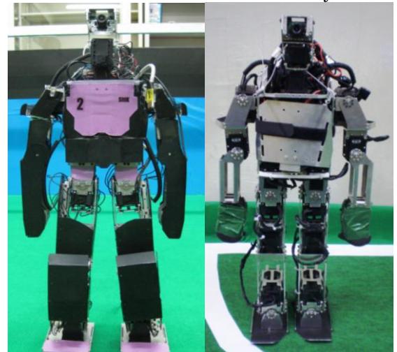
Table 1. Specifications
| Type 2009 | Type 2010 | |
|---|---|---|
| Height [cm] | 59.5 | 55.9 |
| Weight [kg] | 5.0 | 4.3 |
| Walking Speed [m/s] | 0.22 | 0.33 |
| Actuator | Robotis, Dynamixel RX-64 RX-28 | |
| Torque [kg-cm] | 77.2 | 28.3 |
| Speed [sec/60°] | 0.157 | 0.167 |
| Degrees of freedom | 20 in total with 6 in each leg: (RX64×5, RX28×1), 3 in each arm: (RX28×3), 2 in the neck: (RX28×2) | |
| Sensors Camera: Resolution Color space Frame rate [fps] | Point Grey Research, Firefly MV, FFMV-03MTC-CS 640 x 480 YUV, HSV 60, 30, 15, 7.5 | |
| Accelerometer | Kondo Kagaku, RAS-2 | |
| Gyroscope | NEC Tokin, 3D motion sensor, MDP-A3U9S | Kondo Kagaku, KRG-3 Silicon Sensing Systems Japan, CRS03-02S |
| PC Manufacturer | SONY, VAIO typeU | |
| Processor [GHz] | Core Solo 1.20 | |
| Network | IEEE802.11a | |
| Batteries [V] | A123 Systems Cells:18650 Li-Fe 19.8 |
2.1 Specification
The significant features are as follows:
- The robot is equipped with a tiny laptop computer, VAIO type U, for a data processing, especially robot vision, because robot vision needs high computer performance.
- The robot is fully developed by students. The students designed the robot using 3D CAD software (Autodesk Inventor), made it using a CAM machine (Original Mind mini-CNC), and developed software with C++
language.
2.2 Mechanical configuration
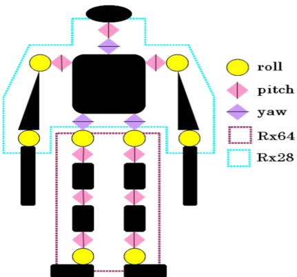
Fig 2 shows a configuration of the actuators. The robot has totally 20 DOFs: 6 DOFs in each leg, 3 DOFs in each arm, and 2 DOFs in the neck for tracking objects by one camera.
Old and new generation robot is the same DOF.
2.3 Controller
The main controller of robot is a tiny laptop computer, VAIO type U, that is a SONY product. VAIO processes an image data from the camera and information (feedback value) of the other sensors from microcomputer, PIC 30F3012. The main controller and actuators communicate each other by sending and receiving data of angle, temperature, and so on. The interface is RS485.
2.4 Sensor
The robot has 3 types of sensors.
- Image sensor (IEEE1394 Camera)
This sensor, Firefly MV, captures an environmental image data in front of the robot. It is controlled by main controller via IEEE1394 interface.
The robot has this 1 sensor.
- Other sensor
Other sensor's analog data is converted digital data by
microcomputer.
The interface between the main controller and microcomputer is RS485.
2.4.1 Accelerometer
This sensor, RAS-2, is 2-axis accelerometer.
The robot has this 1 sensor.
2.4.2 Gyroscope
The robot has 2 types of gyroscope.
The first sensor, KRG-3, is 1-axis gyro sensor.
The robot has this 1 sensor.
Another sensor, CRS03-02S, is 1-axis gyro sensor.
The robot has these 2 sensors.
3 Software
(Software section header)
3.1 Vision System
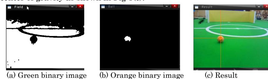
The image from the camera to VAIO is obtained in YUV format and white balance, and then converted into HSV format. In order to detect objects by extracting colors, the images in YUV and HSV are binarized using upper and lower thresholds and the two images are conjugated logically. This method and an illumination-invariant color space method improve robustness and accuracy of the color extractions in various lighting conditions. Furthermore we are trying to find a ball with its shape. Firstly, robot creates a binary image which displayed color of the field (green color) and ball (orange color) from the acquired in Fig 3(a), (b). Secondly robot labels each object in this binary image and calculates the center of gravity and circumference, square measure. Thirdly, robot searches pixel under the center of gravity of orange object in green binary image. Finally, a ball is recognized relation of pixel position and center of gravity as shown in Fig 3(c).
3.2 Walking Control
We adopted the simply Linear Inverted Pendulum Mode (LIPM) for the method of controlling to walk of the robot. The LIPM can keep the height of the center of gravity constant. Therefore if the robots have an
individual specificity, we can easily change the setting of the parameter of center of the center of gravity, and the robot came to be able to do a steady walking.
3.3 Motion Control
The motion performance has been improved in response to the change of the hardware of the robot. Three parameters (the orbit of the motion, transition time of the posture, maximum speed to which the motor can be put out) have been adjusted.
As the result, the maximum distance of the shoot has 6.0m. Speed of getting up is improved from 8s to 5s.
3.4 Network System
SitiK introduces the network system in this year. Network system use UDP (User Datagram Protocol). The robots communicate companion robots and Game controller. Therefore, the robots can do autonomous positioning, and pass other robots.
4 Conclusion
We have developed three new humanoid robots with 20 degrees of freedom and equipped with VAIO typeU for RoboCup 2009. We changed the mechanical design to improve motion performance, robustness, and safety. As the result, the robot can walk 1.5 times faster and more stabilize compared.
The most important change is robustness. We improve hardware. We shortened the leg of the robot, and thickened the frame of the leg from 1.5mm to 2mm. We decreased number of parts of the robot. As the result, Breakdown of the robot became 1/10 or less.
We will continue to develop a vision system more robustly and improve a motion performance. Moreover, the localization will be implemented in the robots in the future.
References
- K. Demura, M. Tani, Y. Hattori: The Yumekobo Project Education at Kanazawa Institute of Technology (in Japanese), Journal of Society for Engineering Education, pp.128-135, 2006
- K. Azeura, G.Ivan: Color Sampling with Omni-Directional Camera in Robot Soccer (in Japanese), Proceedings of the 24th Annual Conference of the of Robotics Society of Japan, CD-ROM 1B25, 2006
- H. Kambayashi, K. Demura: Evaluation of Illumination-Invariant Color Space (in Japanese), Proceedings of the 25th Annual Conference of the of Robotics Society of Japan, CD-ROM 2N24, 2007